YAMAHA RHINO 700 2013 Repair Manual
Manufacturer: YAMAHA, Model Year: 2013, Model line: RHINO 700, Model: YAMAHA RHINO 700 2013Pages: 188, PDF Size: 4.9 MB
Page 61 of 188
4-31
●
Do not deform or damage the cylin-
ders in any way. Cylinder damage will
result in poor damping performance.
●
Do not dispose of a damaged or worn
out shock absorber assembly your-
self. Take the shock absorber assem-
bly to a Yamaha dealer for any
service.
The spring preload, rebound damping and
compression damping forces of the rear
shock absorber assemblies can be adjusted
to suit the operating conditions.NOTICENever turn an adjusting mechanism be-
yond the minimum and maximum settings.
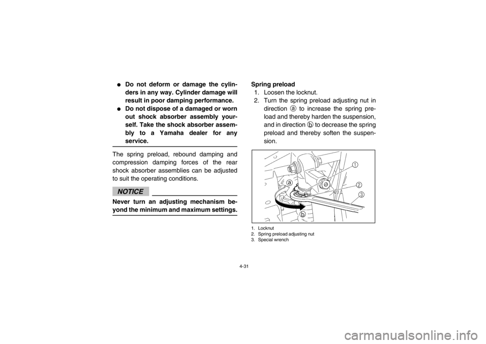
Spring preload
1. Loosen the locknut.
2. Turn the spring preload adjusting nut in direction a to increase the spring pre-
load and thereby harden the suspension,
and in direction b to decrease the spring
preload and thereby soften the suspen-
sion.1. Locknut
2. Spring preload adjusting nut
3. Special wrench
1RB7A_EE.book Page 31 Tuesday, April 24, 2012 9:07 AM
Page 62 of 188
4-32
TIP●
A special wrench can be obtained at a
Yamaha dealer to make this adjustment.
●
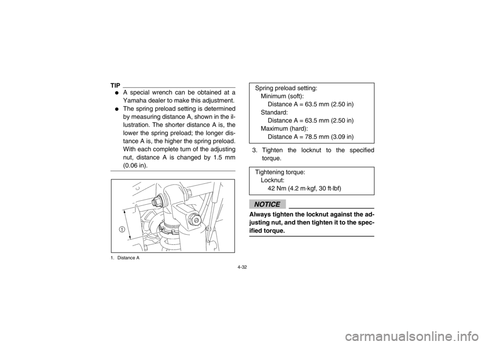
The spring preload setting is determined
by measuring distance A, shown in the il-
lustration. The shorter distance A is, the
lower the spring preload; the longer dis-
tance A is, the higher the spring preload.
With each complete turn of the adjusting
nut, distance A is changed by 1.5 mm
(0.06 in).
1. Distance A
3. Tighten the locknut to the specifiedtorque.NOTICEAlways tighten the locknut against the ad-
justing nut, and then tighten it to the spec-
ified torque.
Spring preload setting:
Minimum (soft): Distance A = 63.5 mm (2.50 in)
Standard: Distance A = 63.5 mm (2.50 in)
Maximum (hard):
Distance A = 78.5 mm (3.09 in)
Tightening torque: Locknut: 42 Nm (4.2 m·kgf, 30 ft·lbf)
1RB7A_EE.book Page 32 Tuesday, April 24, 2012 9:07 AM
Page 63 of 188
4-33
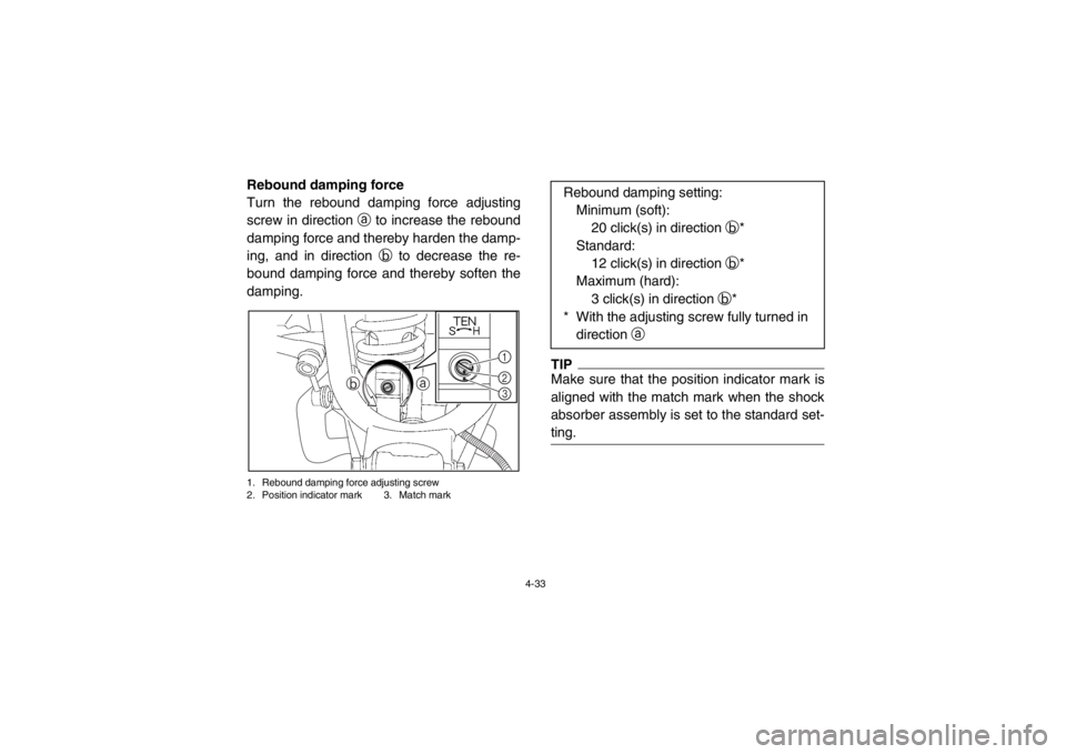
Rebound damping force
Turn the rebound damping force adjusting
screw in direction a to increase the rebound
damping force and thereby harden the damp-
ing, and in direction b to decrease the re-
bound damping force and thereby soften the
damping.1. Rebound damping force adjusting screw
2. Position indicator mark 3. Match mark
TIPMake sure that the position indicator mark is
aligned with the match mark when the shock
absorber assembly is set to the standard set-
ting.
a
b
123
Rebound damping setting:
Minimum (soft): 20 click(s) in direction b*
Standard: 12 click(s) in direction b*
Maximum (hard):
3 click(s) in direction b*
* With the adjusting screw fully turned in direction a
1RB7A_EE.book Page 33 Tuesday, April 24, 2012 9:07 AM
Page 64 of 188
4-34
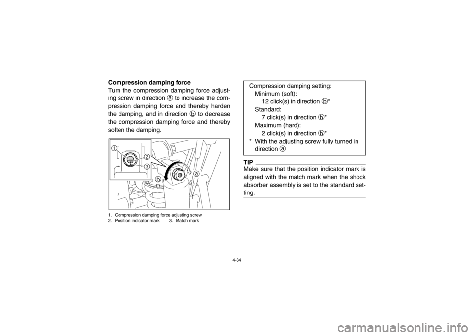
Compression damping force
Turn the compression damping force adjust-
ing screw in direction a to increase the com-
pression damping force and thereby harden
the damping, and in direction b to decrease
the compression damping force and thereby
soften the damping.1. Compression damping force adjusting screw
2. Position indicator mark 3. Match mark
TIPMake sure that the position indicator mark is
aligned with the match mark when the shock
absorber assembly is set to the standard set-
ting.
1
3 2
Compression damping setting:Minimum (soft): 12 click(s) in direction b*
Standard: 7 click(s) in direction b*
Maximum (hard):
2 click(s) in direction b*
* With the adjusting screw fully turned in direction a
1RB7A_EE.book Page 34 Tuesday, April 24, 2012 9:07 AM
Page 65 of 188
4-35
TIPAlthough the total number of clicks of a damp-
ing force adjusting mechanism may not exact-
ly match the above specifications due to small
differences in production, the actual number
of clicks always represents the entire adjust-
ing range. To obtain a precise adjustment, it
would be advisable to check the number of
clicks of each damping force adjusting mech-
anism and to modify the specifications as nec-
essary.
WARNING
●
Suspension components become hot
during operation. Never touch the
compression damping force adjusting
screw, the rebound damping force ad-
justing screw or the oil reservoir with
your bare hand or skin until suspen-
sion components have cooled.
●
Always adjust the shock absorber as-
semblies on the left and right side to
the same setting. Uneven adjustment
can cause poor handling and loss of
stability, which could lead to an acci-
dent.
1RB7A_EE.book Page 35 Tuesday, April 24, 2012 9:07 AM
Page 66 of 188
4-36
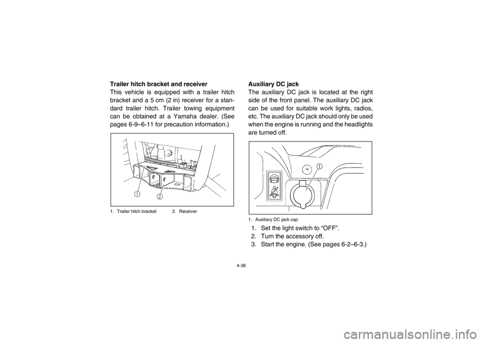
EVU00370Trailer hitch bracket and receiver
This vehicle is equipped with a trailer hitch
bracket and a 5 cm (2 in) receiver for a stan-
dard trailer hitch. Trailer towing equipment
can be obtained at a Yamaha dealer. (See
pages 6-9–6-11 for precaution information.)1. Trailer hitch bracket 2. Receiver
EVU00380Auxiliary DC jack
The auxiliary DC jack is located at the right
side of the front panel. The auxiliary DC jack
can be used for suitable work lights, radios,
etc. The auxiliary DC jack should only be used
when the engine is running and the headlights
are turned off.1. Auxiliary DC jack cap1. Set the light switch to “OFF”.
2. Turn the accessory off.
3. Start the engine. (See pages 6-2–6-3.)
2
1
1RB7A_EE.book Page 36 Tuesday, April 24, 2012 9:07 AM
Page 67 of 188
4-37
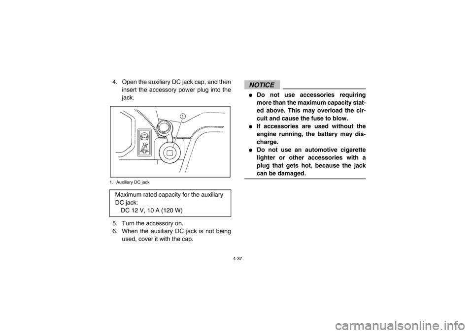
EVU003804. Open the auxiliary DC jack cap, and theninsert the accessory power plug into the
jack.1. Auxiliary DC jack5. Turn the accessory on.
6. When the auxiliary DC jack is not beingused, cover it with the cap.
NOTICE●
Do not use accessories requiring
more than the maximum capacity stat-
ed above. This may overload the cir-
cuit and cause the fuse to blow.
●
If accessories are used without the
engine running, the battery may dis-
charge.
●
Do not use an automotive cigarette
lighter or other accessories with a
plug that gets hot, because the jack
can be damaged.
Maximum rated capacity for the auxiliary
DC jack:DC 12 V, 10 A (120 W)
1RB7A_EE.book Page 37 Tuesday, April 24, 2012 9:07 AM
Page 68 of 188
5-1
EVU01200
1-FOR YOUR SAFETY – PRE-OPERATION CHECKS
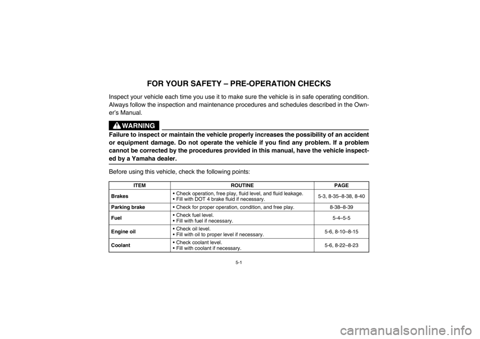
Inspect your vehicle each time you use it to make sure the vehicle is in safe operating condition.
Always follow the inspection and maintenance procedures and schedules described in the Own-
er’s Manual.
WARNING
Failure to inspect or maintain the vehicle properly increases the possibility of an accident
or equipment damage. Do not operate the vehicle if you find any problem. If a problem
cannot be corrected by the procedures provided in this manual, have the vehicle inspect-
ed by a Yamaha dealer.Before using this vehicle, check the following points:
ITEMROUTINE PAGE
Brakes Check operation, free play, fluid level, and fluid leakage.
Fill with DOT 4 brake fluid if necessary. 5-3, 8-35–8-38, 8-40
Parking brake Check for proper operation, condition, and free play. 8-38–8-39
Fuel Check fuel level.
Fill with fuel if necessary. 5-4–5-5
Engine oil Check oil level.
Fill with oil to proper level if necessary. 5-6, 8-10–8-15
Coolant Check coolant level.
Fill with coolant if necessary. 5-6, 8-22–8-23
1RB7A_EE.book Page 1 Tuesday, April 24, 2012 9:07 AM
Page 69 of 188

5-2
1
2
3
45
6
7
8
9
10
11
12
13
14
Final gear oil/
Differential gear oil
Check for leakage. 5-7, 8-15–8-21
Accelerator pedal Check for proper accelerator pedal operation. 5-7
Seat belts Check for proper operation and belt wear. 5-7–5-8
Steering Check for proper operation. 5-8
Fittings and fasteners Check all fittings and fasteners. 5-8
Instruments, lights and
switches Check operation, and correct if necessary. 5-8, 8-55–8-60
Wheels and tires Check tire pressure and for wear and damage. 5-9–5-10, 8-44–8-46
Axle boots Check for damage. 8-23–8-24
ITEM ROUTINE PAGE
1RB7A_EE.book Page 2 Tuesday, April 24, 2012 9:07 AM
Page 70 of 188

5-3
EVU00390Front and rear brakes
Brake pedal
Check that there is no free play in the brake
pedal. If there is free play, have a Yamaha
dealer check the brake system. (See page
8-38.)
Check the operation of the brake pedal. It
should move smoothly and there should be a
firm feeling when the brakes are applied. If
not, have the vehicle inspected by a Yamaha
dealer.
Brake fluid level
Check the brake fluid level. Add fluid if neces-
sary. (See pages 8-36–8-37.)Brake fluid leakage
Check to see if any brake fluid is leaking out of
the pipe joints or the brake fluid reservoir. Ap-
ply the brakes firmly for one minute. If there is
any leakage, have the vehicle inspected by a
Yamaha dealer.
Brake operation
Check the operation of the brakes at the start
of every ride. Test the brakes at slow speed
after starting out to make sure they are work-
ing properly. If the brakes do not provide prop-
er braking performance, inspect the brake
system. (See pages 8-35–8-36, 8-38–8-41.)
Specified brake fluid: DOT 41RB7A_EE.book Page 3 Tuesday, April 24, 2012 9:07 AM