YAMAHA SR400 2016 User Guide
Manufacturer: YAMAHA, Model Year: 2016, Model line: SR400, Model: YAMAHA SR400 2016Pages: 96, PDF Size: 2.52 MB
Page 11 of 96

Safety information
1-5
1
2
3
4
5
6
7
8
9
10
11
12
13
14
appropriate. Refer to page 6-15 for tire
specifications and more information on
replacing your tires.
Transporting the Motorcycle
Be sure to observe following instruc-
tions before transporting the motorcy-
cle in another vehicle.
Remove all loose items from the
motorcycle.
Check that the fuel cock (if
equipped) is in the “OFF” position
and that there are no fuel leaks.
Point the front wheel straight
ahead on the trailer or in the truck
bed, and choke it in a rail to pre-
vent movement.
Shift the transmission in gear (for
models with a manual transmis-
sion).
Secure the motorcycle with tie-
downs or suitable straps that are
attached to solid parts of the mo-
torcycle, such as the frame or up-
per front fork triple clamp (and not,
for example, to rubber-mounted
handlebars or turn signals, or parts
that could break). Choose the lo-
cation for the straps carefully so
the straps will not rub against
painted surfaces during transport.
The suspension should be com-
pressed somewhat by the tie-
downs, if possible, so that the mo-
torcycle will not bounce excessive-
ly during transport.
2RD-28199-E1.book 5 ページ 2015年9月3日 木曜日 午後3時42分
Page 12 of 96
2-1
1
2
3
4
5
6
7
8
9
10
11
12
13
14
Description
EAU63371
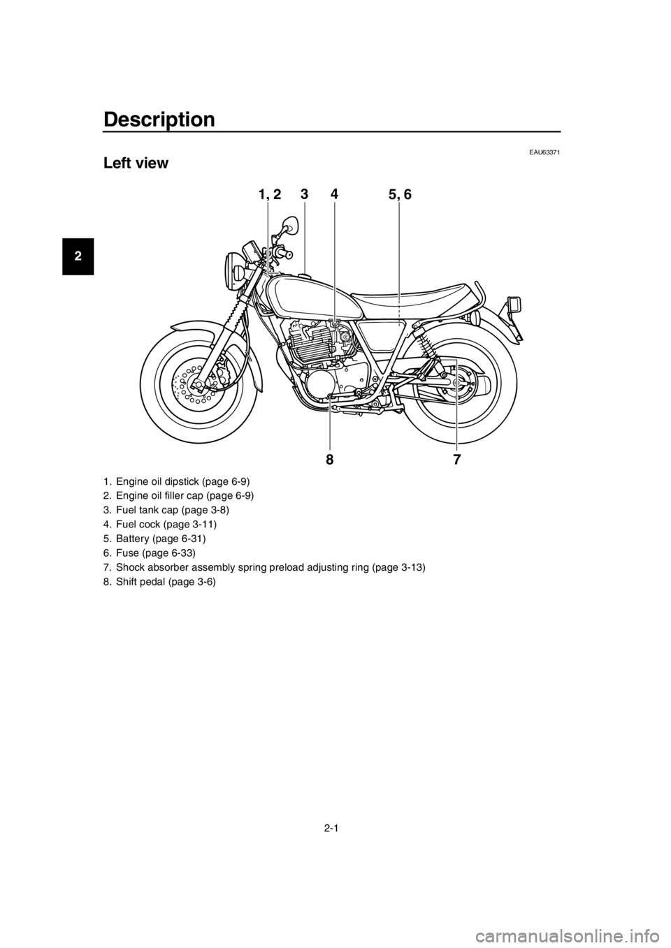
Left view
1. Engine oil dipstick (page 6-9)
2. Engine oil filler cap (page 6-9)
3. Fuel tank cap (page 3-8)
4. Fuel cock (page 3-11)
5. Battery (page 6-31)
6. Fuse (page 6-33)
7. Shock absorber assembly spring preload adjusting ring (page 3-13)
8. Shift pedal (page 3-6)
1, 2 4
5, 63
7
8
2RD-28199-E1.book 1 ページ 2015年9月3日 木曜日 午後3時42分
Page 13 of 96
Description
2-2
1
2
3
4
5
6
7
8
9
10
11
12
13
14
EAU63391
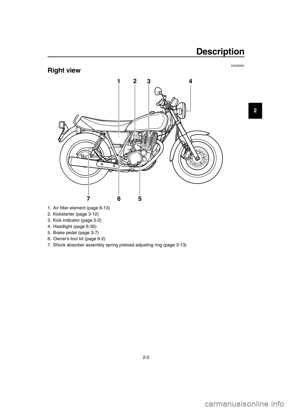
Right view
1. Air filter element (page 6-13)
2. Kickstarter (page 3-12)
3. Kick indicator (page 5-2)
4. Headlight (page 6-35)
5. Brake pedal (page 3-7)
6. Owner’s tool kit (page 6-2)
7. Shock absorber assembly spri ng preload adjusting ring (page 3-13)
12
4
563
7
2RD-28199-E1.book 2 ページ 2015年9月3日 木曜日 午後3時42分
Page 14 of 96
Description
2-3
1
2
3
4
5
6
7
8
9
10
11
12
13
14
EAU63401
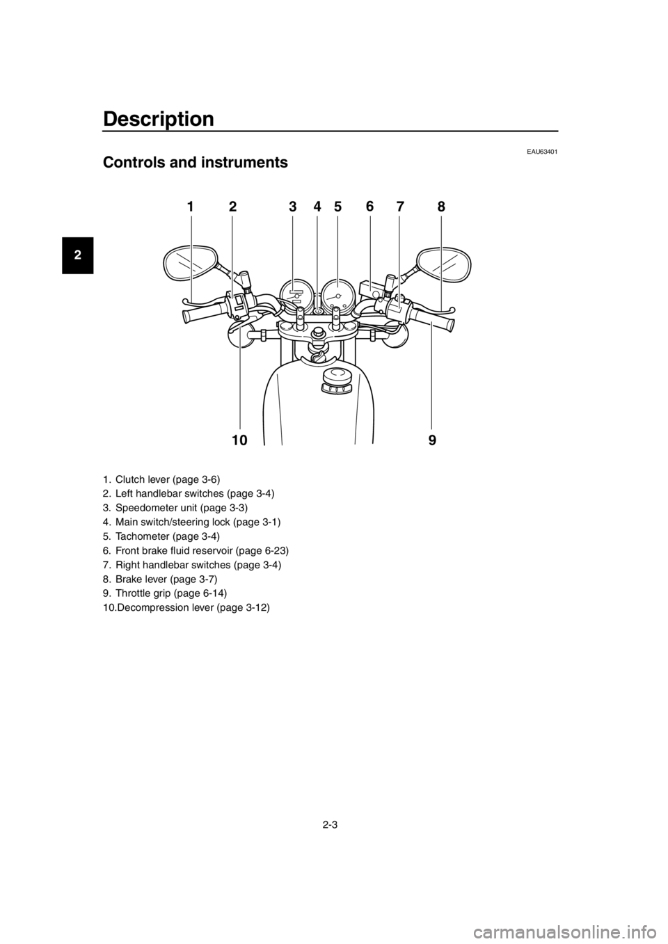
Controls and instruments
1. Clutch lever (page 3-6)
2. Left handlebar switches (page 3-4)
3. Speedometer unit (page 3-3)
4. Main switch/steering lock (page 3-1)
5. Tachometer (page 3-4)
6. Front brake fluid reservoir (page 6-23)
7. Right handlebar switches (page 3-4)
8. Brake lever (page 3-7)
9. Throttle grip (page 6-14)
10.Decompression lever (page 3-12)
12 345 78
9
6
10
2RD-28199-E1.book 3 ページ 2015年9月3日 木曜日 午後3時42分
Page 15 of 96
3-1
1
2
3
4
5
6
7
8
9
10
11
12
13
14
Instrument and control functions
EAU10462
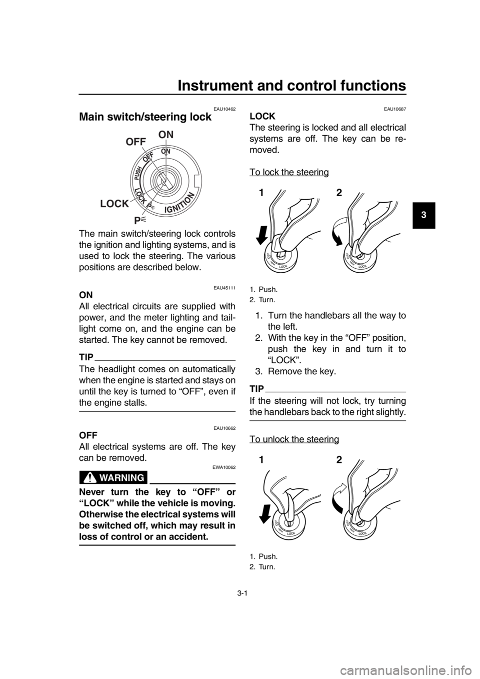
Main switch/steering lock
The main switch/steering lock controls
the ignition and lighting systems, and is
used to lock the steering. The various
positions are described below.
EAU45111ON
All electrical circuits are supplied with
power, and the meter lighting and tail-
light come on, and the engine can be
started. The key cannot be removed.
TIP
The headlight comes on automatically
when the engine is started and stays on
until the key is turned to “OFF”, even if
the engine stalls.
EAU10662OFF
All electrical systems are off. The key
can be removed.
WARNING
EWA10062
Never turn the key to “OFF” or
“LOCK” while the vehicle is moving.
Otherwise the electrical systems will
be switched off, which may result in
loss of control or an accident.
EAU10687LOCK
The steering is locked and all electrical
systems are off. The key can be re-
moved.
To lock the steering
1. Turn the handlebars all the way to the left.
2. With the key in the “OFF” position, push the key in and turn it to
“LOCK”.
3. Remove the key.
TIP
If the steering will not lock, try turning
the handlebars back to the right slightly.
To unlock the steering
P
ON
OFF
LOCK
1. Push.
2. Turn.
1. Push.
2. Turn.
12
12
2RD-28199-E1.book 1 ページ 2015年9月3日 木曜日 午後3時42分
Page 16 of 96
Instrument and control functions
3-2
1
2
3
4
5
6
7
8
9
10
11
12
13
14 1. Insert the key.
2. With the key in the “LOCK” posi-
tion, push the key in and turn it to
“OFF”.
EAU59680 (Parking)
The hazard lights and turn signal lights
can be turned on, but all other electrical
systems are off. The key can be re-
moved.
The steering must be locked before the
key can be turned to “ ”.
NOTICE
ECA20760
Using the hazard or turn signal
lights for an extended length of time
may cause the battery to discharge.
EAU49398
Indicator light s and warning
lights
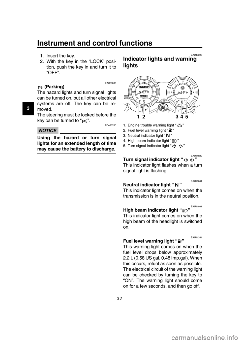
EAU11022Turn signal indicator light “ ”
This indicator light flashes when a turn
signal light is flashing.
EAU11061Neutral indicator light “ ”
This indicator light comes on when the
transmission is in the neutral position.
EAU11081High beam indicator light “ ”
This indicator light comes on when the
high beam of the headlight is switched
on.
EAU11354Fuel level warning light “ ”
This warning light comes on when the
fuel level drops below approximately
2.2 L (0.58 US gal, 0.48 Imp.gal). When
this occurs, refuel as soon as possible.
The electrical circuit of the warning light
can be checked by turning the key to
“ON”. The warning light should come
on for a few seconds, and then go off.
1. Engine trouble warning light “ ”
2. Fuel level warning light “ ”
3. Neutral indicator light “ ”
4. High beam indicator light “ ”
5. Turn signal indicator light “ ”
4
2
153
2RD-28199-E1.book 2 ページ 2015年9月3日 木曜日 午後3時42分
Page 17 of 96

Instrument and control functions
3-3
1
2
3
4
5
6
7
8
9
10
11
12
13
14
If the warning light does not come on
initially when the key is turned to “ON”,
or if the warning light remains on, have
a Yamaha dealer check the electrical
circuit.
EAU11486Engine trouble warning light “ ”
This warning light comes on if a prob-
lem is detected in the electrical circuit
monitoring the engine. If this occurs,
have a Yamaha dealer check the vehi-
cle.
The electrical circuit of the warning light
can be checked by turning the key to
“ON”. The warning light should come
on for a few seconds, and then go off.
If the warning light does not come on
initially when the key is turned to “ON”,
or if the warning light remains on, have
a Yamaha dealer check the electrical
circuit.
EAU11631
Speedometer unit
The speedometer unit is equipped with
a speedometer, an odometer and a
tripmeter. The speedometer shows rid-
ing speed. The odometer shows the to-
tal distance traveled. The tripmeter
shows the distance traveled since it
was last set to zero with the reset knob.
The tripmeter can be used to estimate
the distance that can be traveled with a
full tank of fuel. This information will en-
able you to plan future fuel stops.
1. Reset knob
2. Speedometer
3. Odometer
4. Tripmeter
123 4
2RD-28199-E1.book 3 ページ 2015年9月3日 木曜日 午後3時42分
Page 18 of 96
Instrument and control functions
3-4
1
2
3
4
5
6
7
8
9
10
11
12
13
14
EAU11882
Tachometer
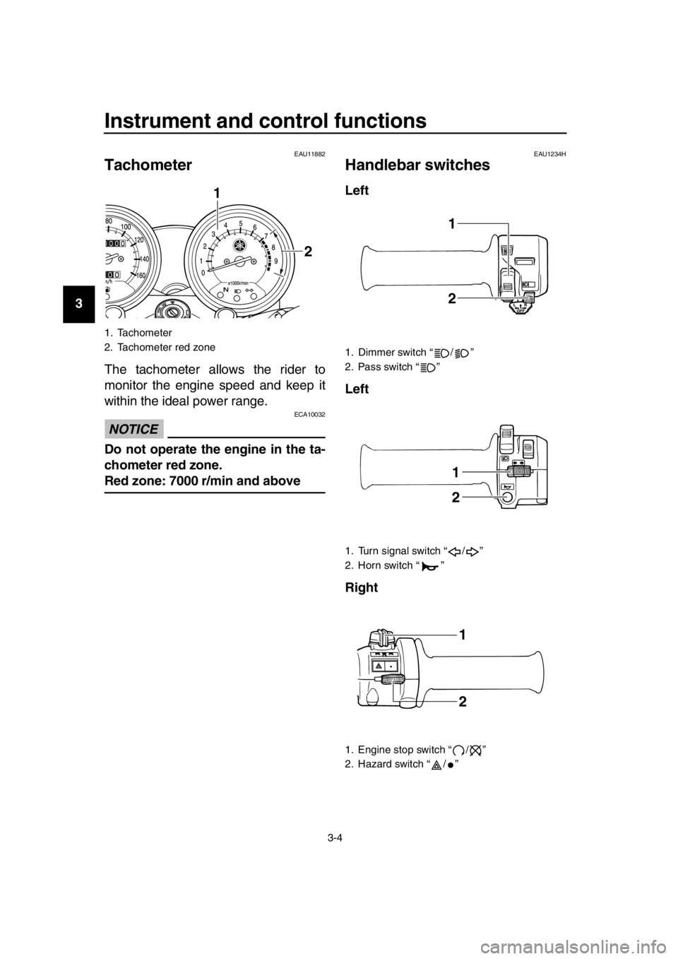
The tachometer allows the rider to
monitor the engine speed and keep it
within the ideal power range.
NOTICE
ECA10032
Do not operate the engine in the ta-
chometer red zone.
Red zone: 7000 r/min and above
EAU1234H
Handlebar switches
Left
Left
Right
1. Tachometer
2. Tachometer red zone
1
2
1. Dimmer switch “ / ”
2. Pass switch “ ”
1. Turn signal switch “ / ”
2. Horn switch “ ”
1. Engine stop switch “ / ”
2. Hazard switch “ / ”
1
2
1
2
1
2
2RD-28199-E1.book 4 ページ 2015年9月3日 木曜日 午後3時42分
Page 19 of 96
Instrument and control functions
3-5
1
2
3
4
5
6
7
8
9
10
11
12
13
14
EAU12352Pass switch “ ”
Press this switch to flash the headlight.
TIP
When the dimmer switch is set to “ ”,
the passing switch has no effect.
EAU12401Dimmer switch “ / ”
Set this switch to “ ” for the high
beam and to “ ” for the low beam.
EAU12461Turn signal switch “ / ”
To signal a right-hand turn, push this
switch to “ ”. To signal a left-hand
turn, push this switch to “ ”. When re-
leased, the switch returns to the center
position. To cancel the turn signal
lights, push the switch in after it has re-
turned to the center position.
EAU12501Horn switch “ ”
Press this switch to sound the horn.
EAU12661Engine stop switch “ / ”
Set this switch to “ ” before starting
the engine. Set this switch to “ ” to
stop the engine in case of an emergen-
cy, such as when the vehicle overturns
or when the throttle cable is stuck.
EAU12735Hazard switch “ ”
With the key in the “ON” or “ ” posi-
tion, use this switch to turn on the haz-
ard lights (simultaneous flashing of all
turn signal lights).
The hazard lights are used in case of
an emergency or to warn other drivers
when your vehicle is stopped where it
might be a traffic hazard.
NOTICE
ECA10062
Do not use the hazard lights for an
extended length of time with the en-
gine not running, otherwise the bat-
tery may discharge.
2RD-28199-E1.book 5 ページ 2015年9月3日 木曜日 午後3時42分
Page 20 of 96
Instrument and control functions
3-6
1
2
3
4
5
6
7
8
9
10
11
12
13
14
EAU12822
Clutch lever
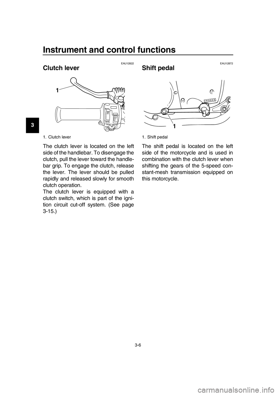
The clutch lever is located on the left
side of the handlebar. To disengage the
clutch, pull the lever toward the handle-
bar grip. To engage the clutch, release
the lever. The lever should be pulled
rapidly and released slowly for smooth
clutch operation.
The clutch lever is equipped with a
clutch switch, which is part of the igni-
tion circuit cut-off system. (See page
3-15.)
EAU12872
Shift pedal
The shift pedal is located on the left
side of the motorcycle and is used in
combination with the clutch lever when
shifting the gears of the 5-speed con-
stant-mesh transmission equipped on
this motorcycle.
1. Clutch lever
1
1. Shift pedal
1
2RD-28199-E1.book 6 ページ 2015年9月3日 木曜日 午後3時42分