check engine light YAMAHA TMAX 2016 User Guide
[x] Cancel search | Manufacturer: YAMAHA, Model Year: 2016, Model line: TMAX, Model: YAMAHA TMAX 2016Pages: 110, PDF Size: 6.26 MB
Page 67 of 110

Periodic maintenance and adjustment
7-10
1
2
3
4
5
6
7
8
9
10
11
12
13
14
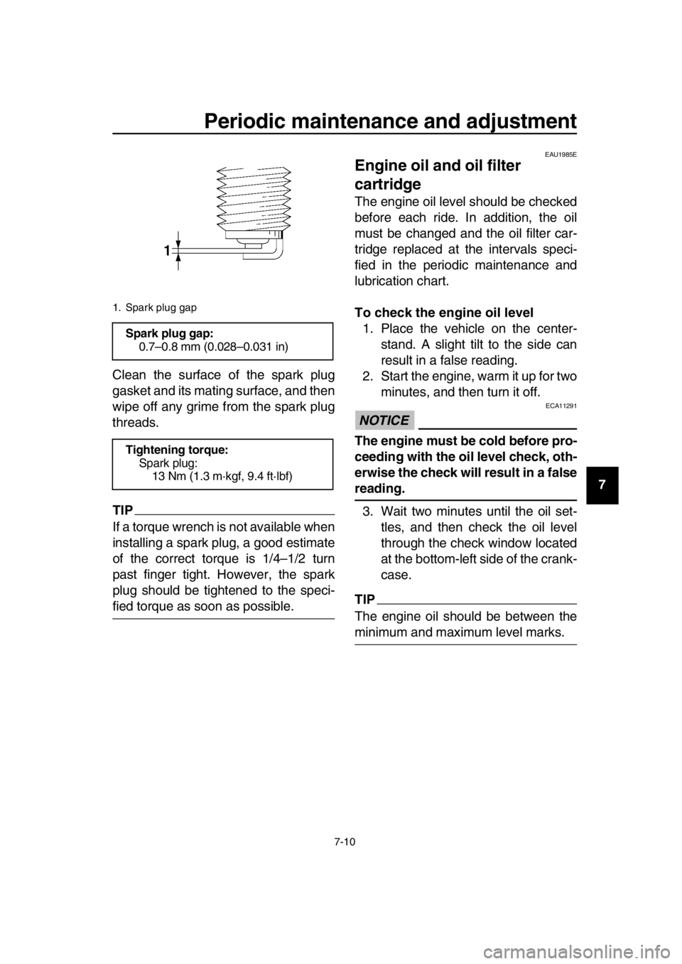
Clean the surface of the spark plug
gasket and its mating surface, and then
wipe off any grime from the spark plug
threads.
TIP
If a torque wrench is not available when
installing a spark plug, a good estimate
of the correct torque is 1/4–1/2 turn
past finger tight. However, the spark
plug should be tightened to the speci-
fied torque as soon as possible.
EAU1985E
Engine oil and oil filter
cartridge
The engine oil level should be checked
before each ride. In addition, the oil
must be changed and the oil filter car-
tridge replaced at the intervals speci-
fied in the periodic maintenance and
lubrication chart.
To check the engine oil level
1. Place the vehicle on the center- stand. A slight tilt to the side can
result in a false reading.
2. Start the engine, warm it up for two minutes, and then turn it off.
NOTICE
ECA11291
The engine must be cold before pro-
ceeding with the oil level check, oth-
erwise the check will result in a false
reading.
3. Wait two minutes until the oil set- tles, and then check the oil level
through the check window located
at the bottom-left side of the crank-
case.
TIP
The engine oil should be between the
minimum and maximum level marks.
1. Spark plug gap
Spark plug gap:0.7–0.8 mm (0.028–0.031 in)
Tightening torque: Spark plug:
13 Nm (1.3 m·kgf, 9.4 ft·lbf)
2PW-9-E1.book 10 ページ 2015年9月10日 木曜日 午後5時17分
Page 70 of 110

Periodic maintenance and adjustment
7-13
1
2
3
4
5
6
7
8
9
10
11
12
13
14 lubricates the clutch), do not
mix any chemical additives. Do
not use oils with a diesel speci-
fication of “CD” or oils of a high-
er quality than specified. In
addition, do not use oils labeled
“ENERGY CONSERVING II” or
higher.
Make sure that no foreign mate-
rial enters the crankcase.
11. Start the engine, and then let it idle for several minutes while checking
it for oil leakage. If oil is leaking, im-
mediately turn the engine off and
check for the cause.
12. Turn the engine off, and then check the oil level and correct it if
necessary.
13. Reset the oil change indicator. (See page 4-6.)
TIP
If the engine oil is changed before the
oil change indicator comes on (i.e. be-
fore the periodic oil change interval has
been reached), the indicator must be
reset after the oil change for the next
periodic oil change to be indicated at
the correct time.
EAU20071
Coolant
The coolant level should be checked
before each ride. In addition, the cool-
ant must be changed at the intervals
specified in the periodic maintenance
and lubrication chart.
EAU52024To check the coolant level1. Place the vehicle on the center- stand.
TIP
The coolant level must be checked
on a cold engine since the level
varies with engine temperature.
Make sure that the vehicle is posi-
tioned straight up when checking
the coolant level. A slight tilt to the
side can result in a false reading.
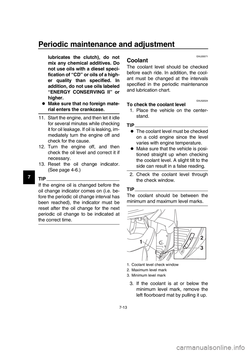
2. Check the coolant level through the check window.
TIP
The coolant should be between the
minimum and maximum level marks.
3. If the coolant is at or below the minimum level mark, remove the
left floorboard mat by pulling it up.
1. Coolant level check window
2. Maximum level mark
3. Minimum level mark
12
3
2PW-9-E1.book 13 ページ 2015年9月10日 木曜日 午後5時17分
Page 95 of 110

Periodic maintenance and adjustment
7-38
1
2
3
4
5
6
7
8
9
10
11
12
13
14
EAU61545
Emergency mode
When the smart key is lost, damaged,
or its battery has discharged, the vehi-
cle can still be turned on and the engine
started. You will need a mechanical key
and the smart key system identification
number. (See page 3-3.) To operate
the vehicle in emergency mode, carry
out the following steps.
TIP
Emergency mode operation will be
cancelled if the respective steps are not
carried out within the time set for each
operation or if the “OFF/LOCK” switch
is pushed. 1. Stop the vehicle in a safe place.
2. Unlock the seat by inserting the mechanical key into the lock inside
the front storage compartment and
turn it clockwise.
3. Open the seat and check that the trunk light comes on.
4. Push the “ON/ ” switch once.
5. Without completely shutting the seat, raise and lower it three times
within 10 seconds.
TIP
Use the rear storage compartment light
as a guide when raising and lowering
the seat. The smart key system indicator
light on the speedometer will come
on for three seconds to indicate
the transition to emergency mode.
6. After the smart key system indica- tor light goes off, use the “SEAT
OPEN/ ” switch to enter the
identification number. Refer to the
following procedure on how to in-
put the identification number.
7. Inputting the identification number is done by counting the number of
flashes of the smart key system in-
dicator light.
For example, if the identification
number is 123456:
Push and hold the “SEAT
OPEN/ ” switch.
The smart key system indicator
1. Smart key system indicator light “ ”
1. Identification number
1
1 1
2PW-9-E1.book 38 ページ 2015年9月10日 木曜日 午後5時17分
Page 107 of 110

11-1
1
2
3
4
5
6
7
8
9
10
11
12
13
14
Index
A
ABS (for ABS models) ...........................4-13
ABS warning light (for ABS models)........4-1
Acceleration and deceleration .................6-3
Air filter element, replacing ....................7-15
Auxiliary DC jack ...................................4-24
Auxiliary lights .......................................7-32
B
Battery ...................................................7-28
Brake fluid, changing .............................7-23
Brake fluid level, checking .....................7-22
Brake lever, front ...................................4-11
Brake lever, rear ....................................4-12
Brake levers, lubricating ........................7-25
Braking ....................................................6-4
C
Cables, checking and lubricating...........7-24
Care.........................................................8-1
Catalytic converter.................................4-16
Centerstand and sidestand, checking and lubricating .....................7-26
Coolant ..................................................7-13
D
Dimmer switch .......................................4-10
Drive belt slack ......................................7-24
E
Emergency mode ..................................7-38
Engine break-in .......................................6-5
Engine idling speed ...............................7-16
Engine oil and oil filter cartridge ............7-10
Engine serial number ............................10-1
Engine stop switch ................................4-10
Engine trouble warning light ....................4-1
F
Front and rear brake lever free play,
checking ..............................................7-20
Front and rear brake pads, checking.....7-22
Front fork, checking ...............................7-26
Fuel .......................................................4-15
Fuel consumption, tips for reducing ........6-5
Fuel tank cap .........................................4-14
Fuses, replacing ....................................7-29
H
Handlebar switches ...............................4-10
Hazard switch ........................................4-10
Headlights .............................................7-31
Helmet holder ........................................4-17
High beam indicator light .........................4-1
Horn switch............................................4-10
How to lock the steering ........................3-10
I
Identification numbers ........................... 10-1
Ignition circuit cut-off system................. 4-22
Indicator lights and warning lights ........... 4-1
K
Key, handling of smart and mechanical
key ........................................................ 3-3
L
License plate light bulb, replacing ......... 7-34
M
Maintenance and lubrication, periodic .... 7-4
Maintenance, emission control system ... 7-3
Matte color, caution................................. 8-1
Model label............................................ 10-2
Multi-function display .............................. 4-3
O
ON/Start switch ..................................... 4-10
Operating range of the smart key system .................................................. 3-2
P
Panels, removing and installing .............. 7-7
Parking .................................................... 6-6
Parking mode ........................................ 3-11
Part locations .......................................... 2-1
Pass switch ........................................... 4-10
Powering off the vehicle .......................... 3-9
R
Rear brake lock cable, adjusting ........... 7-21
Rear brake lock, checking..................... 7-21
Rear brake lock lever ............................ 4-12
Rear view mirrors .................................. 4-21
Rider backrest, adjusting ...................... 4-17
S
Safe-riding points .................................... 1-5
Safety information ................................... 1-1
Seat opening and closing...................... 3-10
Shock absorber assembly..................... 4-21
Sidestand .............................................. 4-22
Smart key ................................................ 3-5
Smart key battery, replacing ................... 3-6
Smart key system ................................... 3-1
Smart key system indicator light ............. 4-2
Spark plugs, checking ............................. 7-9
Specifications .......................................... 9-1
Speedometer .......................................... 4-2
Starting off............................................... 6-3
Starting the engine .................................. 6-2
Steering, checking ................................ 7-27
Storage ................................................... 8-4
Storage compartments.......................... 4-18
2PW-9-E1.book 1 ページ 2015年9月10日 木曜日 午後5時17分