check engine light YAMAHA TMAX 2016 Owners Manual
[x] Cancel search | Manufacturer: YAMAHA, Model Year: 2016, Model line: TMAX, Model: YAMAHA TMAX 2016Pages: 110, PDF Size: 6.26 MB
Page 5 of 110

Table of contents
Safety information............................ 1-1
Further safe-riding points ................ 1-5
Description ........................................ 2-1
Left view .......................................... 2-1
Right view ........................................ 2-2
Controls and instruments ................ 2-3
Smart key system ............................. 3-1
Smart key system ............................ 3-1
Operating range of the smart key system............. ....................... ...... 3-2
Handling of the smart key and
mechanical key ............................ 3-3
Smart key ........................................ 3-5
Replacing the smart key battery ...... 3-6
Vehicle power on and steering lock release .................................. 3-8
Powering off the vehicle .................. 3-9
How to lock the steering ................ 3-10
Seat opening and closing .............. 3-10
Parking mode ................................ 3-11
Instrument and control functions ... 4-1
Indicator lights and warning lights ... 4-1
Speedometer .............. ..................... 4-2
Tachometer ..................................... 4-3
Multi-function display ....................... 4-3
Handlebar switches ....................... 4-10
Front brake lever ........................... 4-11
Rear brake lever ............................ 4-12
Rear brake lock lever .................... 4-12
ABS (for ABS models) ................... 4-13
Fuel tank cap ................................. 4-14
Fuel ............................................... 4-15
Catalytic converter......................... 4-16
Adjusting the rider backrest ........... 4-17
Helmet holder ................................ 4-17
Storage compartments .................. 4-18
Windshield ..................................... 4-19
Rear view mirrors .......................... 4-21
Shock absorber assembly ............. 4-21
Sidestand ...................................... 4-22
Ignition circuit cut- off system ......... 4-22
Auxiliary DC jack ........................... 4-24 For your safety – pre-operation
checks
............................................... 5-1
Operation and important riding
points ................................................. 6-1
Starting the engine .......................... 6-2
Starting off....................................... 6-3
Acceleration and deceleration......... 6-3
Braking ............................................ 6-4
Tips for reducing fuel
consumption ................................ 6-5
Engine break-in ............................... 6-5
Parking ............................................ 6-6
Periodic maintenance and
adjustment ........................................ 7-1
Owner’s tool kit ............................... 7-2
Periodic maintenance chart for the emission control system ........ 7-3
General maintenance and lubrication chart ........................... 7-4
Removing and installing panels ...... 7-7
Checking the spark plugs................ 7-9
Engine oil and oil filter cartridge .... 7-10
Coolant.......................................... 7-13
Replacing the air filter element ..... 7-15
Adjusting the engine idling speed ......................................... 7-16
Checking the throttle grip free play ............................................ 7-16
Valve clearance ............................ 7-17
Tires .............................................. 7-17
Cast wheels .................................. 7-19
Checking the front and rear brake lever free play .................. 7-20
Adjusting the rear brake lock
cable .......................................... 7-21
Checking the rear brake lock ........ 7-21
Checking the front and rear
brake pads ................................. 7-22
Checking the brake fluid level ....... 7-22
Changing the brake fluid ............... 7-23
Drive belt slack.............................. 7-24
Checking and lubricating the cables ........................................ 7-24
2PW-9-E1.book 1 ページ 2015年9月10日 木曜日 午後5時17分
Page 22 of 110

Smart key system
3-8
1
2
3
4
5
6
7
8
9
10
11
12
13
14
EAU61633
Vehicle power on and steering
lock release
1. With the smart key on and in oper- ating range, press the “ON/ ”
switch for one second.
2. Upon authentication of the smart key, the beeper will sound twice,
the smart key system indicator
light will come on momentarily and
the steering lock (if applied) will re-
lease automatically.
TIP
The smart key system indicator
light will flash if the steering lock
cannot automatically release itself.
Try moving the handlebars gently
to the left or right and then press
the “ON/ ” switch.
If the steering continues to be
locked and will not release, the
smart key system indicator light
will flash 16 times and the steering
lock release operation will stop
midway. Move the handlebar gen-
tly to the left and right to help re-
lease the steering lock and then
press the “ON/ ” switch again.
NOTICE
ECA15825
If the steering lock will not release
and the smart key system indicator
light is flashing, have a Yamaha
dealer check the smart key system.
3. The power of the vehicle is turned on once the steering lock is com-
pletely released. The smart key
system indicator light will go off
and the multi-function meter dis-
play will come on.
4. The engine can now be started. (See page 6-2.)
1. “ON/ ” switch
1
2PW-9-E1.book 8 ページ 2015年9月10日 木曜日 午後5時17分
Page 26 of 110

4-1
1
2
3
4
5
6
7
8
9
10
11
12
13
14
Instrument and control functions
EAU49398
Indicator ligh ts and warning
lights
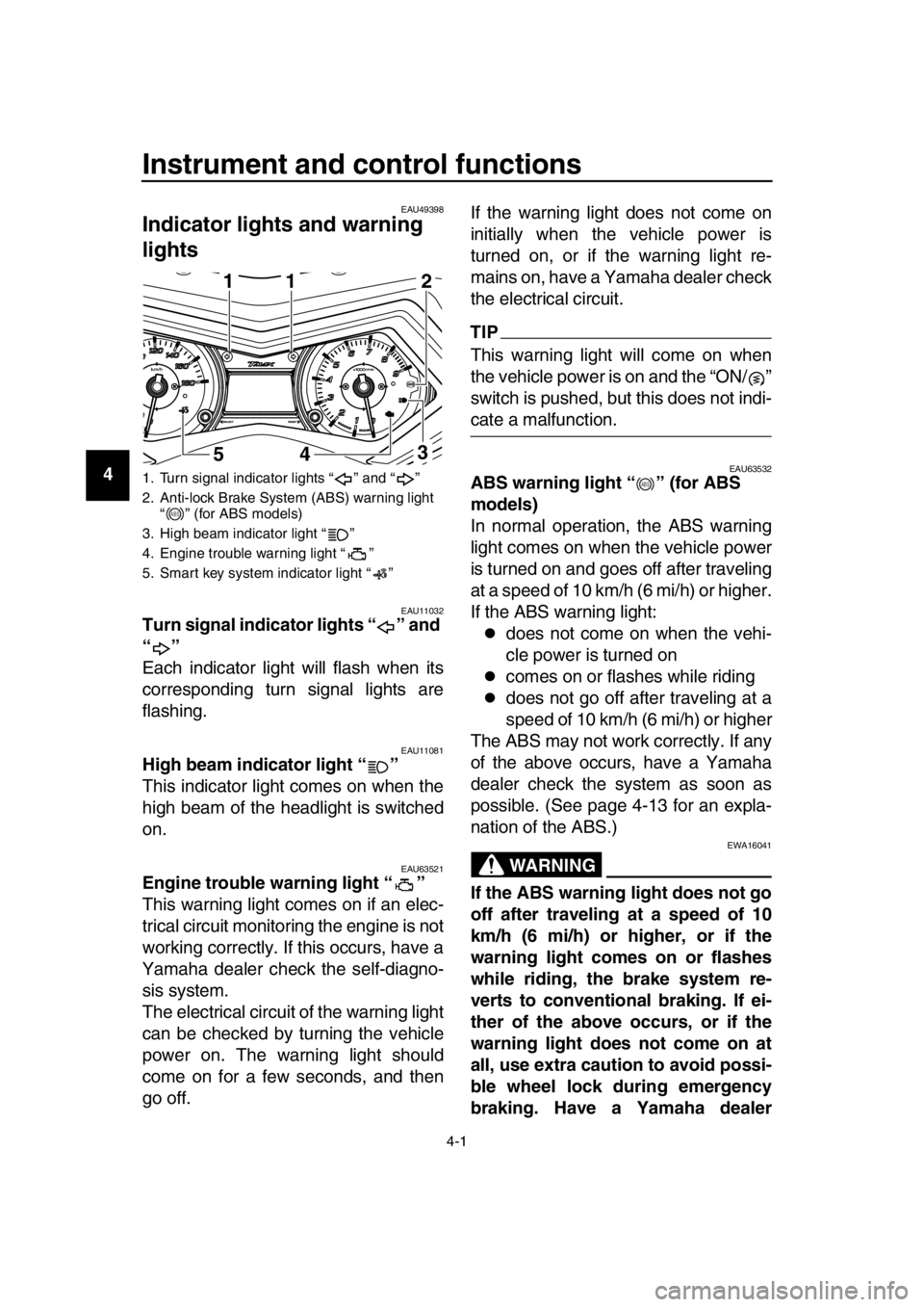
EAU11032Turn signal indicator lights “ ” and
“”
Each indicator light will flash when its
corresponding turn signal lights are
flashing.
EAU11081High beam indicator light “ ”
This indicator light comes on when the
high beam of the headlight is switched
on.
EAU63521Engine trouble warning light “ ”
This warning light comes on if an elec-
trical circuit monitoring the engine is not
working correctly. If this occurs, have a
Yamaha dealer check the self-diagno-
sis system.
The electrical circuit of the warning light
can be checked by turning the vehicle
power on. The warning light should
come on for a few seconds, and then
go off. If the warning light does not come on
initially when the vehicle power is
turned on, or if the warning light re-
mains on, have a Yamaha dealer check
the electrical circuit.
TIP
This warning light will come on when
the vehicle power is on and the “ON/ ”
switch is pushed, but this does not indi-
cate a malfunction.
EAU63532ABS warning light “ ” (for ABS
models)
In normal operation, the ABS warning
light comes on when the vehicle power
is turned on and goes off after traveling
at a speed of 10 km/h (6 mi/h) or higher.
If the ABS warning light:
does not come on when the vehi-
cle power is turned on
comes on or flashes while riding
does not go off after traveling at a
speed of 10 km/h (6 mi/h) or higher
The ABS may not work correctly. If any
of the above occurs, have a Yamaha
dealer check the system as soon as
possible. (See page 4-13 for an expla-
nation of the ABS.)
WARNING
EWA16041
If the ABS warning light does not go
off after traveling at a speed of 10
km/h (6 mi/h) or higher, or if the
warning light comes on or flashes
while riding, the brake system re-
verts to conventional braking. If ei-
ther of the above occurs, or if the
warning light does not come on at
all, use extra caution to avoid possi-
ble wheel lock during emergency
braking. Have a Yamaha dealer
1. Turn signal indicator lights “ ” and “ ”
2. Anti-lock Brake System (ABS) warning light “ ” (for ABS models)
3. High beam indicator light “ ”
4. Engine trouble warning light “ ”
5. Smart key system indicator light “ ”
1
5411
3 2
ABS
ABS
2PW-9-E1.book 1 ページ 2015年9月10日 木曜日 午後5時17分
Page 27 of 110

Instrument and control functions
4-2
1
2
3
4
5
6
7
8
9
10
11
12
13
14
check the brake system and electri-
cal circuits as soon as possible.
TIP
If the start switch is pushed while
the engine is running, the ABS
warning light will come on, but this
is not a malfunction.
The ABS warning light may come
on when revving the engine with
the scooter on its centerstand, but
this does not indicate a malfunc-
tion.
EAU61652Smart key system indicator light
“”
This indicator light communicates the
status of the smart key system. When
the smart key system is operating nor-
mally, this indicator light will be off. If
there is an error in the smart key sys-
tem, the indicator light will flash. The in-
dicator light will
also flash when
communication between the vehicle
and smart key takes place and when
certain smart key system operations
are carried out. (See page 3-1.)
TIP
When the start switch is pushed, the in-
dicator light will come on for about one
second and then go off. If the indicator
light does not come on or go off as nor-
mal, have a Yamaha dealer check the
vehicle.
EAU63541
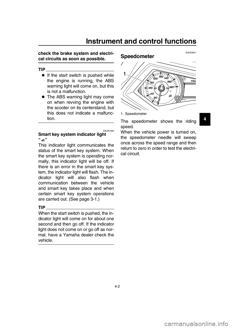
Speedometer
The speedometer shows the riding
speed.
When the vehicle power is turned on,
the speedometer needle will sweep
once across the speed range and then
return to zero in order to test the electri-
cal circuit.
1. Speedometer
1
2PW-9-E1.book 2 ページ 2015年9月10日 木曜日 午後5時17分
Page 34 of 110

Instrument and control functions
4-9
1
2
3
4
5
6
7
8
9
10
11
12
13
14 Instantaneous fuel consumption modeThis mode calculates the current fuel
consumption rate of the vehicle every
few seconds.
For the UK:
The instantaneous fuel consumption is
displayed “MPG”.
When the display is set to “km/L”,
the distance that can be traveled
on 1.0 L of fuel under the current
riding conditions is shown.
When the display is set to “L/100
km”, the amount of fuel necessary
to travel 100 km under the current
riding conditions is shown.
For the UK: The distance that can
be traveled on 1.0 Imp.gal of fuel
under the current riding conditions
is shown.
To switch between the instantaneous
fuel consumption displays, push the
“RESET” button for one second when
one of the displays is shown (except for
the UK).
TIP
If traveling at speeds under 10 km/h (6
mi/h), “_ _._” is displayed. Self-diagnosis device
This model is equipped with a self-diag-
nosis device for vari
ous electrical cir-
cuits.
If a problem is detected in any of those
circuits, the engine trouble warning light
comes on and the display indicates an
error code.
If the display indicates any error codes,
note the code number, and then have a
Yamaha dealer check the vehicle.
NOTICE
ECA11591
If the display indicates an error
code, the vehicle should be checked
as soon as possible in order to avoid
engine damage.
1. Instantaneous fuel consumption display
1
1. Error code display
1
2PW-9-E1.book 9 ページ 2015年9月10日 木曜日 午後5時17分
Page 47 of 110

Instrument and control functions
4-22
1
2
3
4
5
6
7
8
9
10
11
12
13
14
EAU15306
Sidestand
The sidestand is located on the left side
of the frame. Raise the sidestand or
lower it with your foot while holding the
vehicle upright.
TIP
The built-in sidestand switch is part of
the ignition circuit cut-off system, which
cuts the ignition in certain situations.
(See the following section for an expla-
nation of the ignition circuit cut-off sys-
tem.)
WARNING
EWA10242
The vehicle must not be ridden with
the sidestand down, or if the sides-
tand cannot be properly moved up
(or does not stay up), otherwise the
sidestand could contact the ground
and distract the operator, resulting
in a possible loss of control.
Yamaha’s ignition circuit cut-off
system has been designed to assist
the operator in fulfilling the respon-
sibility of raising the sidestand be-
fore starting off. Therefore, check
this system regularly and have a
Yamaha dealer repair it if it does not
function properly.
EAU66770
Ignition circuit cut-off system
The ignition circuit cut-off system (com-
prising the sidestand switch and brake
light switches) has the following func-
tions.
It prevents starting when the side-
stand is up, but neither brake is ap-
plied.
It prevents starting when either
brake is applied, but the sidestand
is still down.
It cuts the running engine when the
sidestand is moved down.
Periodically check the operation of the
ignition circuit cut-o ff system according
to the following procedure.
2PW-9-E1.book 22 ページ 2015年9月10日 木曜日 午後5時17分
Page 53 of 110

Operation and important riding points
6-2
1
2
3
4
5
6
7
8
9
10
11
12
13
14
EAU61552
Starting the engine
NOTICE
ECA10251
See page 6-5 for engine break-in in-
structions prior to operating the ve-
hicle for the first time.
In order for the ignition circuit cut-off
system to enable starting, the sides-
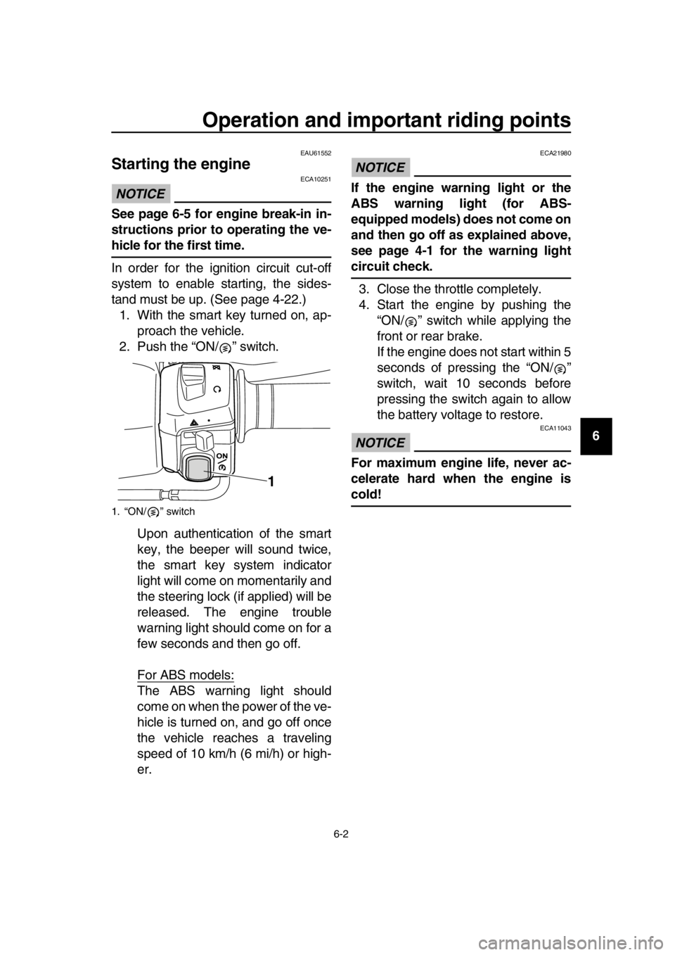
tand must be up. (See page 4-22.) 1. With the smart key turned on, ap- proach the vehicle.
2. Push the “ON/ ” switch.
Upon authentication of the smart
key, the beeper will sound twice,
the smart key system indicator
light will come on momentarily and
the steering lock (if applied) will be
released. The engine trouble
warning light should come on for a
few seconds and then go off.
For ABS models:
The ABS warning light should
come on when the power of the ve-
hicle is turned on, and go off once
the vehicle reaches a traveling
speed of 10 km/h (6 mi/h) or high-
er.
NOTICE
ECA21980
If the engine warning light or the
ABS warning light (for ABS-
equipped models) does not come on
and then go off as explained above,
see page 4-1 for the warning light
circuit check.3. Close the throttle completely.
4. Start the engine by pushing the “ON/ ” switch while applying the
front or rear brake.
If the engine does not start within 5
seconds of pressing the “ON/ ”
switch, wait 10 seconds before
pressing the switch again to allow
the battery voltage to restore.
NOTICE
ECA11043
For maximum engine life, never ac-
celerate hard when the engine is
cold!
1. “ON/ ” switch
1
2PW-9-E1.book 2 ページ 2015年9月10日 木曜日 午後5時17分
Page 56 of 110

Operation and important riding points
6-5
1
2
3
4
5
6
7
8
9
10
11
12
13
14
EAU16821
Tips for reducing fuel
consumption
Fuel consumption depends largely on
your riding style. Consider the following
tips to reduce fuel consumption:
Avoid high engine speeds during
acceleration.
Avoid high engine speeds with no
load on the engine.
Turn the engine off instead of let-
ting it idle for an extended length of
time (e.g., in traffic jams, at traffic
lights or at railroad crossings).
EAU16842
Engine break-in
There is never a more important period
in the life of your engine than the period
between 0 and 1600 km (1000 mi). For
this reason, you should read the follow-
ing material carefully.
Since the engine is brand new, do not
put an excessive load on it for the first
1600 km (1000 mi). The various parts in
the engine wear and polish themselves
to the correct operating clearances.
During this period, prolonged full-throt-
tle operation or any condition that might
result in engine overheating must be
avoided.
EAU36532
0–1000 km (0–600 mi)
Avoid prolonged operation above 4100
r/min. NOTICE: After 1000 km (600
mi) of operation, the engine oil must
be changed, and the oil filter car-
tridge or element replaced.
[ECA11283]
1000–1600 km (600–1000 mi)
Avoid prolonged operation above 5000
r/min.
1600 km (1000 mi) and beyond
The vehicle can now be operated nor-
mally.
NOTICE
ECA10311
Keep the engine speed out of
the tachometer red zone.
If any engine trouble should oc-
cur during the engine break-in
period, immediately have a
Yamaha dealer check the vehi-
cle.
2PW-9-E1.book 5 ページ 2015年9月10日 木曜日 午後5時17分
Page 63 of 110

Periodic maintenance and adjustment
7-6
1
2
3
4
5
6
7
8
9
10
11
12
13
14
EAU38263
TIP
Engine air filter and V-belt air filters This model’s engine air fi lter is equipped with a disposable oil-coated paper
element, which must not be cleaned wi th compressed air to avoid damaging
it.
The engine air filter element needs to be replaced and the V-belt air filter el- ements need to be serviced more frequently when riding in unusually wet or
dusty areas.
Hydraulic brake service After disassembling the brake master cylinders and calipers, always change the fluid. Regularly check the brake fluid levels and fill the reservoirs
as required.
Every two years replace the internal components of the brake master cylin-
ders and calipers, and change the brake fluid.
Replace the brake hoses every four years and if cracked or damaged.
27 Moving parts and
cables Lubricate.
28 *Throttle grip Check operation.
Check throttle grip free play,
and adjust if necessary.
Lubricate cable and grip housing.
29 *Lights, signals and
switches Check operation.
Adjust headlight beam.
NO. ITEM
X 1000 km
CHECK OR
MAINTENANCE JOB
X 1000 mi
ODOMETER READINGS
ANNUAL CHECK
110203040
0.66121824
2PW-9-E1.book 6 ページ 2015年9月10日 木曜日 午後5時17分
Page 66 of 110

Periodic maintenance and adjustment
7-9
1
2
3
4
5
6
7
8
9
10
11
12
13
14 To install the panel
Place the panel in the original position,
and then install the screws.
EAU19643
Checking the spark plugs
The spark plugs are important engine
components, which should be checked
periodically, preferably by a Yamaha
dealer. Since heat and deposits will
cause any spark plug to slowly erode,
they should be removed and checked
in accordance with the periodic mainte-
nance and lubrication
chart. In addition,
the condition of the spark plugs can re-
veal the condition of the engine.
The porcelain insulator around the cen-
ter electrode of each spark plug should
be a medium-to-light tan (the ideal color
when the vehicle is ridden normally),
and all spark plugs installed in the en-
gine should have the same color. If any
spark plug shows a distinctly different
color, the engine could be operating im-
properly. Do not attempt to diagnose
such problems yourself. Instead, have
a Yamaha dealer check the vehicle.
If a spark plug shows signs of electrode
erosion and excessive carbon or other
deposits, it should be replaced.
Before installing a spark plug, the spark
plug gap should be measured with a
wire thickness gauge and, if necessary,
adjusted to specification.
1. Screw
2. Panel D
1
2
1
Specified spark plug:
NGK/CR7E
2PW-9-E1.book 9 ページ 2015年9月10日 木曜日 午後5時17分