YAMAHA TMAX 2021 Owners Manual
Manufacturer: YAMAHA, Model Year: 2021, Model line: TMAX, Model: YAMAHA TMAX 2021Pages: 124, PDF Size: 7.93 MB
Page 91 of 124
Periodic maintenance an d a djustment
8-20
8
wei
ght of ri der, passen ger, car-
g o, an d accessories approve d
for this mo del.
WARNING
EWA10512
Never overload your vehicle. Opera-
tion of an overloa ded vehicle coul d
cause an acci dent.
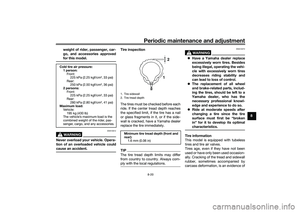
Tire inspection
The tires must be checked before each
ride. If the center tread depth reaches
the specified limit, if the tire has a nail
or glass fragments in it, or if the side-
wall is cracked, have a Yamaha dealer
replace the tire immediately.TIPThe tire tread depth limits may differ
from country to country. Always com-
ply with the local regulations.
WARNING
EWA10472
Have a Yamaha dealer replace
excessively worn tires. Besi des
b ein g ille gal, operatin g the vehi-
cle with excessively worn tires
d ecreases ri din g sta bility an d
can lead to loss of control.
The replacement of all wheel
and b rake-relate d parts, inclu d-
in g the tires, shoul d b e left to a
Yamaha dealer, who has the
necessary professional knowl-
e dg e an d experience to d o so.
Ride at mo derate spee ds after
chan gin g a tire since the tire
surface must first b e “broken
in” for it to d evelop its optimal
characteristics.Tire information
This model is equipped with tubeless
tires and tire air valves.
Tires age, even if they have not been
used or have only been used occasion-
ally. Cracking of the tread and sidewall
rubber, sometimes accompanied by
carcass deformation, is an evidence of
Col d tire air pressure:
1 person: Front: 225 kPa (2.25 kgf/cm², 33 psi)
Rear: 250 kPa (2.50 kgf/cm², 36 psi)
2 persons:
Front: 225 kPa (2.25 kgf/cm², 33 psi)
Rear:
280 kPa (2.80 kgf/cm², 41 psi)
Maximum loa d:
Veh ic le:
195 kg (430 lb)
The vehicle’s maximum load is the
combined weight of the rider, pas-
senger, cargo, and any accessories.
1. Tire sidewall
2. Tire tread depth
Minimum tire trea d d epth (front an d
rear): 1.6 mm (0.06 in)
1 2
UB3TE1E0.book Page 20 Friday, September 11, 2020 8:48 AM
Page 92 of 124
Periodic maintenance an d a djustment
8-21
8 ageing. Old and aged tires shall be
checked by tire specialists to ascertain
their suitability for further use.
WARNING
EWA16101
The front an d rear tires shoul d
b e of the same make an d d e-
si gn, otherwise the han dlin g
characteristics of the vehicle
may be different, which coul d
lea d to an acci dent.
Always make sure that the valve
caps are securely installed to
prevent air pressure leakag e.
Use only the tire valves an d
valve cores listed below to
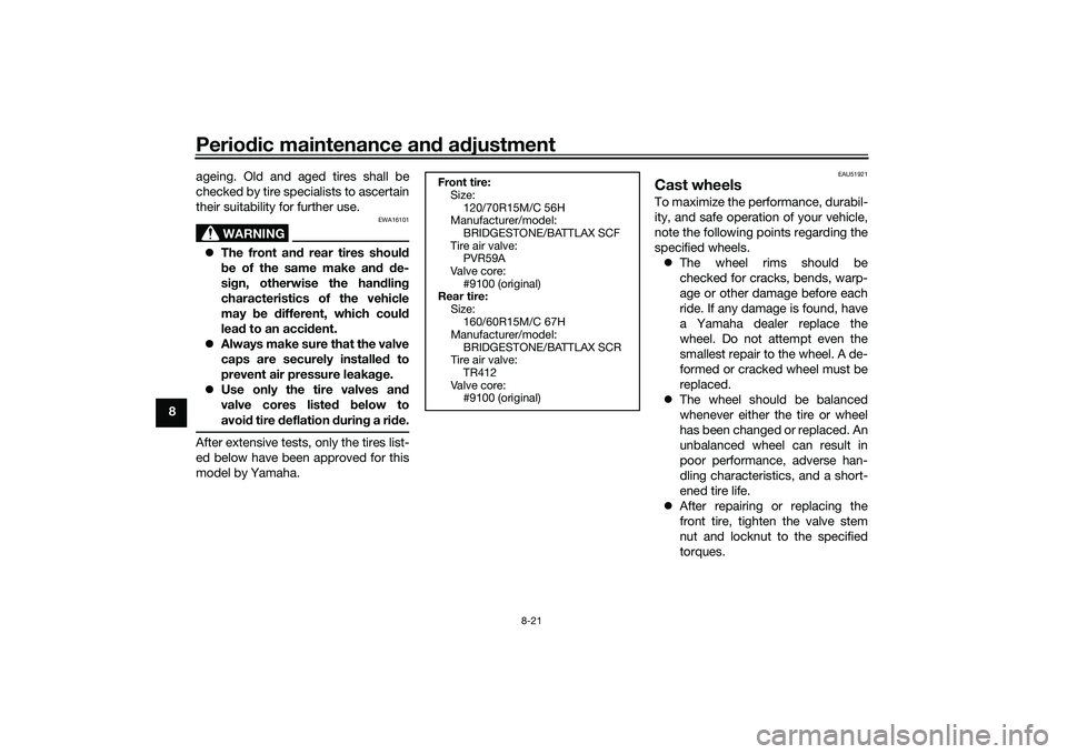
avoi d tire d eflation durin g a ri de.After extensive tests, only the tires list-
ed below have been approved for this
model by Yamaha.
EAU51921
Cast wheelsTo maximize the performance, durabil-
ity, and safe operation of your vehicle,
note the following points regarding the
specified wheels.
The wheel rims should be
checked for cracks, bends, warp-
age or other damage before each
ride. If any damage is found, have
a Yamaha dealer replace the
wheel. Do not attempt even the
smallest repair to the wheel. A de-
formed or cracked wheel must be
replaced.
The wheel should be balanced
whenever either the tire or wheel
has been changed or replaced. An
unbalanced wheel can result in
poor performance, adverse han-
dling characteristics, and a short-
ened tire life.
After repairing or replacing the
front tire, tighten the valve stem
nut and locknut to the specified
torques.
Front tire:
Size:
120/70R15M/C 56H
Manufacturer/model:
BRIDGESTONE/BATTLAX SCF
Tire air valve: PVR59A
Valve core: #9100 (original)
Rear tire:
Size:160/60R15M/C 67H
Manufacturer/model:
BRIDGESTONE/BATTLAX SCR
Tire air valve: TR412
Valve core: #9100 (original)
UB3TE1E0.book Page 21 Friday, September 11, 2020 8:48 AM
Page 93 of 124

Periodic maintenance an d a djustment
8-22
8
EAU50861
Checkin g the front an d rear
b rake lever free playFront
Rear There should be no free play at the
brake lever ends. If there is free play,
have a Yamaha dealer inspect the
brake system.
WARNING
EWA14212
A soft or spon
gy feelin g in the b rake
lever can in dicate the presence of
air in the hy draulic system. If there is
air in the hy draulic system, have a
Yamaha dealer blee d the system be-
fore operatin g the vehicle. Air in the
hy draulic system will diminish the
b rakin g performance, which may re-
sult in loss of control an d an acci-
d ent.
1. Valve stem nut
2. Valve stem locknutTi ghtenin g torques:
Valve stem nut: 2.0 N·m (0.20 kgf·m, 1.5 lb·ft)
Valve stem locknut:
3.0 N·m (0.30 kgf·m, 2.2 lb·ft)
1
2
1. No brake lever free play
1. No brake lever free play
1
1
UB3TE1E0.book Page 22 Friday, September 11, 2020 8:48 AM
Page 94 of 124

Periodic maintenance an d a djustment
8-23
8
EAU53033
A djustin g the rear brake lock
ca blePeriodically check the rear brake lock
cable length and adjust if necessary.
1. Release the rear brake lock lever.
2. To increase the rear brake lock ca- ble length, turn the adjusting nut at
the rear brake caliper in direction
(a). To decrease the rear brake
lock cable length, turn the adjust-
ing nut in direction (b). 3. Confirm that the rear brake lock
lever (page 5-18) functions prop-
erly and that the rear wheel rotates
freely when unlocked.
WARNING
EWA20290
If proper a djustment cannot be o b-
taine d as d escri bed , have a Yamaha
d ealer make this ad justment.
EAU52293
Checking the rear brake lockThe rear brake lock must be checked
at the intervals specified in the periodic
maintenance and lubrication chart.
1. Adjust the rear brake lock cable.
2. Apply the rear brake lock, and then try to push the vehicle to con-
firm that the rear brake lock func-
tions properly.
3. The rear brake lock caliper is pro- vided with a wear indicator, which
allows you to check the rear brake
lock pads. To check the rear brake
lock pads, check the position of
the indicator when the rear brake
lock lever is applied. If the indica-
tor has passed the wear indicator
groove, have a Yamaha dealer
check the rear brake lock.
4. Make sure that there are no tears or cracks on the rubber boot.
1. Adjusting nut
2. Rear brake lock cable lengthRear brake lock cab le length:
43–45 mm (1.69–1.77 in)
1
2
(b)
(a)
UB3TE1E0.book Page 23 Friday, September 11, 2020 8:48 AM
Page 95 of 124

Periodic maintenance an d a djustment
8-24
8
EAU22312
Checkin g the front an d rear
b rake pa dsFront brake
Rear brake The front and rear brake pads must be
checked for wear at the intervals spec-
ified in the periodic maintenance and
lubrication chart. Each brake pad is
provided with a wear indicator, which
allows you to check the brake pad
wear without having to disassemble
the brake. To check the brake pad
wear, check the position of the wear in-
dicator while applying the brake. If a
brake pad has worn to the point that
the wear indicator almost touches the
brake disc, have a Yamaha dealer re-
place the brake pads as a set.
1. Wear indicator groove
2. Wear indicator
3. Rubber boot
1
2
3
1. Brake pad wear indicator
1. Brake pad wear indicator
1
1
UB3TE1E0.book Page 24 Friday, September 11, 2020 8:48 AM
Page 96 of 124
Periodic maintenance an d a djustment
8-25
8
EAU22584
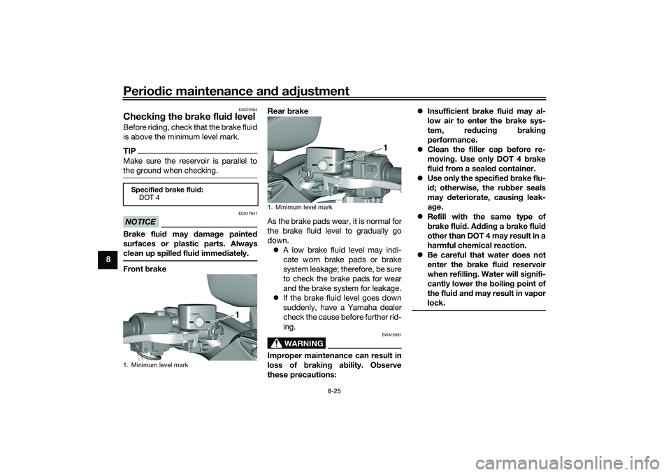
Checkin g the brake flui d levelBefore riding, check that the brake fluid
is above the minimum level mark.TIPMake sure the reservoir is parallel to
the ground when checking.NOTICE
ECA17641
Brake fluid may damag e painted
surfaces or plastic parts. Always
clean up spille d flui d imme diately.Front brake Rear
brake
As the brake pads wear, it is normal for
the brake fluid level to gradually go
down. A low brake fluid level may indi-
cate worn brake pads or brake
system leakage; therefore, be sure
to check the brake pads for wear
and the brake system for leakage.
If the brake fluid level goes down
suddenly, have a Yamaha dealer
check the cause before further rid-
ing.
WARNING
EWA15991
Improper maintenance can result in
loss of b raking a bility. O bserve
these precautions:
Insufficient brake flui d may al-
low air to enter the brake sys-
tem, re ducin g brakin g
performance.
Clean the filler cap before re-
movin g. Use only DOT 4 brake
flui d from a seale d container.
Use only the specified b rake flu-
i d ; otherwise, the ru bber seals
may deteriorate, causin g leak-
a g e.
Refill with the same type of
brake flui d. A ddin g a brake flui d
other than DOT 4 may result in a
harmful chemical reaction.
Be careful that water d oes not
enter the brake flui d reservoir
when refillin g. Water will si gnifi-
cantly lower the boilin g point of
the flui d an d may result in vapor
lock.
Specifie d b rake flui d:
DOT 41. Minimum level mark
LOWER
1
1. Minimum level mark
LOWER
1
UB3TE1E0.book Page 25 Friday, September 11, 2020 8:48 AM
Page 97 of 124
Periodic maintenance an d a djustment
8-26
8
EAU22734
Chang ing the brake flui dHave a Yamaha dealer change the
brake fluid every 2 years. In addition,
have the seals of the master cylinders
and brake calipers, as well as the brake
hoses replaced at the intervals listed
below or sooner if they are damaged or
leaking.
Brake seals: every 2 years
Brake hoses: every 4 years
EAU88810
Drive beltThe drive belt should be visually in-
spected before each ride. Check for
excessive wear, damage, and dirt. Al-
so, the drive belt tension must be
checked and adjusted by a Yamaha
dealer at the intervals specified in the
periodic maintenance chart.
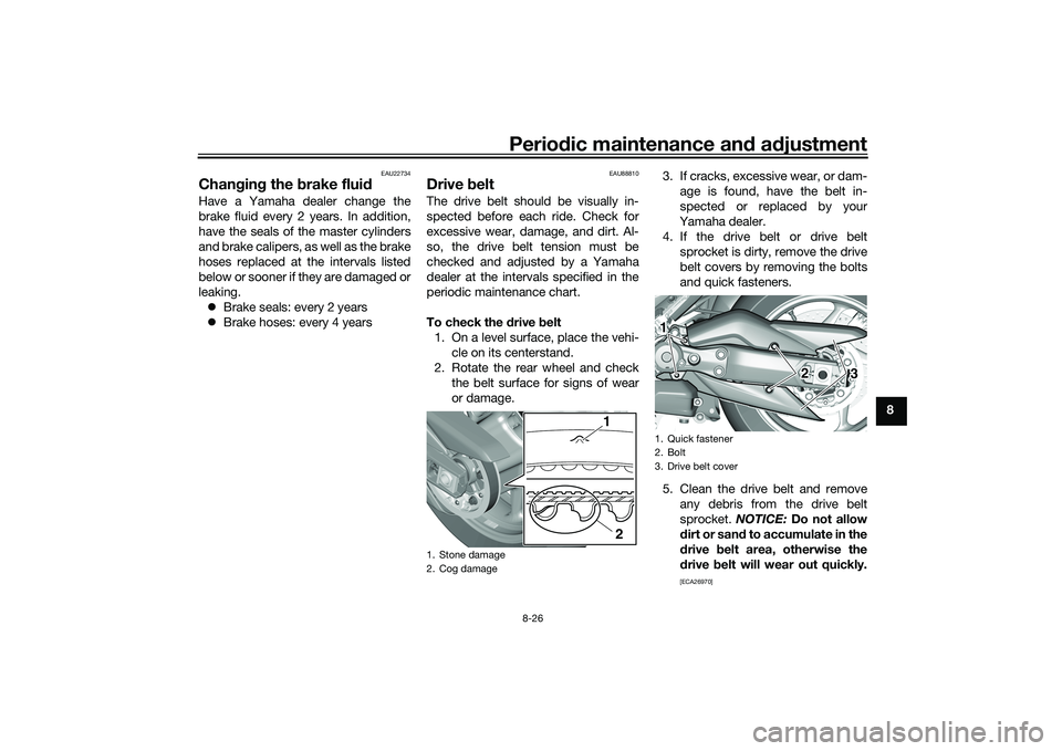
To check the drive belt
1. On a level surface, place the vehi- cle on its centerstand.
2. Rotate the rear wheel and check the belt surface for signs of wear
or damage. 3. If cracks, excessive wear, or dam-
age is found, have the belt in-
spected or replaced by your
Yamaha dealer.
4. If the drive belt or drive belt sprocket is dirty, remove the drive
belt covers by removing the bolts
and quick fasteners.
5. Clean the drive belt and remove any debris from the drive belt
sprocket. NOTICE: Do not allow
d irt or san d to accumulate in the
d rive belt area, otherwise the
d rive belt will wear out quickly.
[ECA26970]
1. Stone damage
2. Cog damage
1
2
1. Quick fastener
2. Bolt
3. Drive belt cover1 23
UB3TE1E0.book Page 26 Friday, September 11, 2020 8:48 AM
Page 98 of 124
Periodic maintenance an d a djustment
8-27
8 6. Install the drive belt covers by in-
stalling the bolts and quick fasten-
ers.
EAU23098
Checkin g an d lu bricatin g the
cab lesThe operation of all control cables and
the condition of the cables should be
checked before each ride, and the ca-
bles and cable ends should be lubri-
cated if necessary. If a cable is
damaged or does not move smoothly,
have a Yamaha dealer check or re-
place it. WARNING! Dama ge to the
outer housin g of cab les may result
in internal rustin g an d cause inter-
ference with cab le movement. Re-
place damag ed cab les as soon as
possi ble to prevent unsafe con di-
tions.
[EWA10712] EAU23115
Checkin
g an d lu bricatin g the
throttle grip an d ca bleThe operation of the throttle grip
should be checked before each ride. In
addition, the cable should be lubricat-
ed by a Yamaha dealer at the intervals
specified in the periodic maintenance
chart.
The throttle cable is equipped with a
rubber cover. Make sure that the cover
is securely installed. Even though the
cover is installed correctly, it does not
completely protect the cable from wa-
ter entry. Therefore, use care not to
pour water directly onto the cover or
cable when washing the vehicle. If the
cable or cover becomes dirty, wipe
clean with a moist cloth.
Recommen ded lu bricant:
Yamaha cable lubricant or other
suitable cable lubricant
UB3TE1E0.book Page 27 Friday, September 11, 2020 8:48 AM
Page 99 of 124
Periodic maintenance an d a djustment
8-28
8
EAU23173
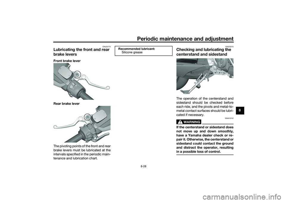
Lu bricatin g the front an d rear
b rake leversFront brake lever
Rear brake lever
The pivoting points of the front and rear
brake levers must be lubricated at the
intervals specified in the periodic main-
tenance and lubrication chart.
EAU23215
Checkin g an d lu bricatin g the
centerstan d an d si destan dThe operation of the centerstand and
sidestand should be checked before
each ride, and the pivots and metal-to-
metal contact surfaces should be lubri-
cated if necessary.
WARNING
EWA10742
If the centerstan d or si destan d d oes
not move up an d d own smoothly,
have a Yamaha dealer check or re-
pair it. Otherwise, the centerstan d or
si destan d coul d contact the g round
an d d istract the operator, resultin g
in a possi ble loss of control.
Recommen ded lu bricant:
Silicone grease
UB3TE1E0.book Page 28 Friday, September 11, 2020 8:48 AM
Page 100 of 124
Periodic maintenance an d a djustment
8-29
8
EAU23273
Checkin g the front forkThe condition and operation of the
front fork must be checked as follows
at the intervals specified in the periodic
maintenance and lubrication chart.
To check the con dition
Check the inner tubes for scratches,
damage and excessive oil leakage.
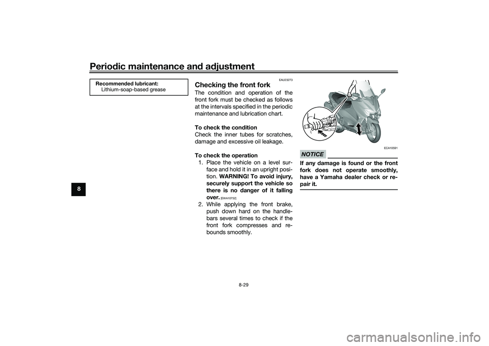
To check the operation 1. Place the vehicle on a level sur- face and hold it in an upright posi-
tion. WARNING! To avoi d injury,
securely support the vehicle so
there is no dan ger of it fallin g
over.
[EWA10752]
2. While applying the front brake, push down hard on the handle-
bars several times to check if the
front fork compresses and re-
bounds smoothly.
NOTICE
ECA10591
If any d amage is foun d or the front
fork does not operate smoothly,
have a Yamaha dealer check or re-
pair it.
Recommen ded lu bricant:
Lithium-soap-based grease
UB3TE1E0.book Page 29 Friday, September 11, 2020 8:48 AM