YAMAHA TZR50 2012 Workshop Manual
Manufacturer: YAMAHA, Model Year: 2012, Model line: TZR50, Model: YAMAHA TZR50 2012Pages: 92, PDF Size: 5.1 MB
Page 51 of 92
4. Remove the oil filler cap, refillwith the specified amount of the
recommended transmission oil,
and then install and tighten the oil
filler cap. NOTICE: Make sure
that no foreign material enters
the transmission case.
[ECAM1021]
5. Start the engine and let it idle for several minutes while checking
the transmission oil case for oil
leakage. If oil is leaking, imme-
diately turn the engine off and
check for the cause.
EAU20070
Coolant
The coolant level should be checked
before each ride. In addition, the coo-
lant must be changed at the intervals
specified in the periodic maintenance
and lubrication chart.
EAU39087
To check the coolant level1. Place the vehicle on a level surfa- ce and hold it in an upright posi-
tion.
TIP
�The coolant level must be chec-
ked on a cold engine since the
level varies with engine tempera-
ture.
�Make sure that the vehicle is
positioned straight up when
checking the coolant level. A
slight tilt to the side can result in
a false reading.
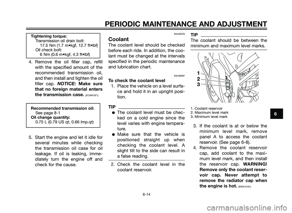
2. Check the coolant level in thecoolant reservoir.
TIP
The coolant should be between the
minimum and maximum level marks.
1. Coolant reservoir
2. Maximum level mark
3. Minimum level mark
3. If the coolant is at or below theminimum level mark, remove
panel A to access the coolant
reservoir. (See page 6-8).
4. Remove the coolant reservoir cap, add coolant to the maxi-
mum level mark, and then install
the reservoir cap. WARNING!
Remove only the coolant reser-
voir cap. Never attempt to
remove the radiator cap when
the engine is hot.
[EWA15161]
Recommended transmission oil: See page 8-1
Oil change quantity: 0.75 L (0.79 US qt, 0.66 Imp.qt)
Tightening torque:Transmission oil drain bolt: 17.5 Nm (1.7 m•kgf, 12.7 ft•lbf)
Oil check bolt: 6 Nm (0.6 m•kgf, 4.3 ft•lbf)
PERIODIC MAINTENANCE AND ADJUSTMENT
6-14
6
1HD-F819D-E0 7/3/11 20:27 Página 51
2AS-F819D-E0.indd 5131/07/12 10:09
Page 52 of 92
NOTICE: If coolant is not avai-
lable, use distilled water or soft
tap water instead. Do not use
hard water or salt water since it
is harmful to the engine. If
water has been used instead of
coolant, replace it with coolant
as soon as possible, otherwise
the cooling system will not be
protected against frost and
corrosion. If water has been
added to the coolant, have a
Yamaha dealer check the anti-
freeze content of the coolant
as soon as possible, otherwise
the effectiveness of the coolant
will be reduced.
[ECA10472]
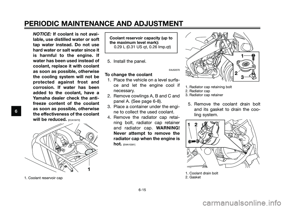
1. Coolant reservoir cap
5. Install the panel.
EAUS2070
To change the coolant 1. Place the vehicle on a level surfa- ce and let the engine cool if
necessary.
2. Remove cowlings A, B and C and panel A. (See page 6-8).
3. Place a container under the engi- ne to collect the used coolant.
4. Remove the radiator cap retai- ning bolt, radiator cap retainer
and radiator cap. WARNING!
Never attempt to remove the
radiator cap when the engine is
hot.
[EWA10381]
1. Radiator cap retaining bolt
2. Radiator cap
3. Radiator cap retainer
5. Remove the coolant drain boltand its gasket to drain the coo-
ling system.
1. Coolant drain bolt
2. Gasket
Coolant reservoir capacity (up to
the maximum level mark):0.29 L (0.31 US qt, 0.26 Imp.qt)
PERIODIC MAINTENANCE AND ADJUSTMENT
6-15
6
1HD-F819D-E0 7/3/11 20:27 Página 52
2AS-F819D-E0.indd 5231/07/12 10:09
Page 53 of 92
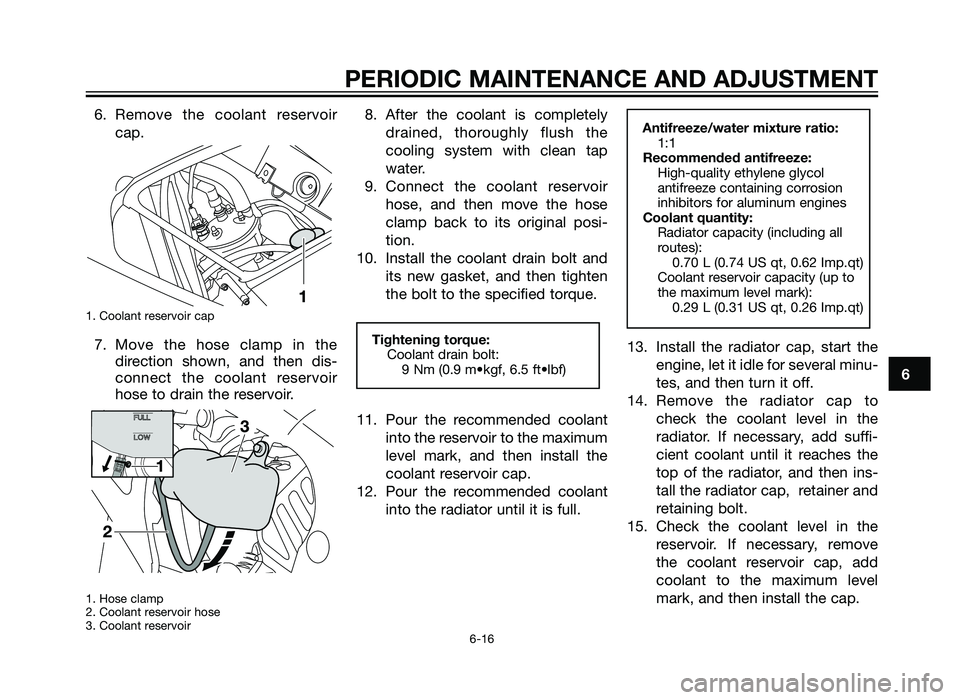
6. Remove the coolant reservoircap.
1. Coolant reservoir cap
7. Move the hose clamp in thedirection shown, and then dis-
connect the coolant reservoir
hose to drain the reservoir.
1. Hose clamp
2. Coolant reservoir hose
3. Coolant reservoir
8. After the coolant is completely
drained, thoroughly flush the
cooling system with clean tap
water.
9. Connect the coolant reservoir hose, and then move the hose
clamp back to its original posi-
tion.
10. Install the coolant drain bolt and its new gasket, and then tighten
the bolt to the specified torque.
11. Pour the recommended coolant into the reservoir to the maximum
level mark, and then install the
coolant reservoir cap.
12. Pour the recommended coolant into the radiator until it is full. 13. Install the radiator cap, start the
engine, let it idle for several minu-
tes, and then turn it off.
14. Remove the radiator cap to check the coolant level in the
radiator. If necessary, add suffi-
cient coolant until it reaches the
top of the radiator, and then ins-
tall the radiator cap, retainer and
retaining bolt.
15. Check the coolant level in the reservoir. If necessary, remove
the coolant reservoir cap, add
coolant to the maximum level
mark, and then install the cap.Antifreeze/water mixture ratio:1:1
Recommended antifreeze: High-quality ethylene glycol
antifreeze containing corrosion
inhibitors for aluminum engines
Coolant quantity: Radiator capacity (including all
routes): 0.70 L (0.74 US qt, 0.62 Imp.qt)
Coolant reservoir capacity (up to
the maximum level mark): 0.29 L (0.31 US qt, 0.26 Imp.qt)
Tightening torque:Coolant drain bolt: 9 Nm (0.9 m•kgf, 6.5 ft•lbf)
PERIODIC MAINTENANCE AND ADJUSTMENT
6-16
6
1HD-F819D-E0 7/3/11 20:27 Página 53
2AS-F819D-E0.indd 5331/07/12 10:09
Page 54 of 92
16. Start the engine, and then checkthe vehicle for coolant leakage. If
coolant is leaking, have a Yama-
ha dealer check the cooling sys-
tem.
17. Install the cowlings and panel.EAU40371
Air filter element
The air filter element should be clea-
ned or replaced at the intervals speci-
fied in the periodic maintenance and
lubrication chart. Have a Yamaha
dealer clean or replace the air filter
element.
EAU21280
Adjusting the carburetor
The carburetor is an important part of
the engine and requires very sophisti-
cated adjustment. Therefore, most
carburetor adjustments should be left
to a Yamaha dealer, who has the
necessary professional knowledge
and experience. The adjustment des-
cribed in the following section, howe-
ver, may be serviced by the owner as
part of routine maintenance.
ECA10550
The carburetor has been set and
extensively tested at the Yamaha
factory. Changing these settings
without sufficient technical know-
ledge may result in poor perfor-
mance of or damage to the engine.
NOTICE
PERIODIC MAINTENANCE AND ADJUSTMENT
6-17
6
1HD-F819D-E0 7/3/11 20:27 Página 54
2AS-F819D-E0.indd 5431/07/12 10:09
Page 55 of 92
EAU33482
Adjusting the engine idling
speed
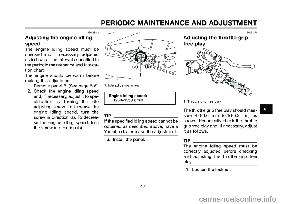
The engine idling speed must be
checked and, if necessary, adjusted
as follows at the intervals specified in
the periodic maintenance and lubrica-
tion chart.
The engine should be warm before
making this adjustment.1. Remove panel B. (See page 6-8).
2. Check the engine idling speed and, if necessary, adjust it to spe-
cification by turning the idle
adjusting screw. To increase the
engine idling speed, turn the
screw in direction (a). To decrea-
se the engine idling speed, turn
the screw in direction (b).
1. Idle adjusting screw
TIP
If the specified idling speed cannot be
obtained as described above, have a
Yamaha dealer make the adjustment.
3. Install the panel.
EAU21374
Adjusting the throttle grip
free play
1. Throttle grip free play
The throttle grip free play should mea-
sure 4.0-6.0 mm (0.16-0.24 in) as
shown. Periodically check the throttle
grip free play and, if necessary, adjust
it as follows.
TIP
The engine idling speed must be
correctly adjusted before checking
and adjusting the throttle grip free
play.
1. Loosen the locknut.
Engine idling speed:1250–1350 r/min
PERIODIC MAINTENANCE AND ADJUSTMENT
6-18
6
1HD-F819D-E0 7/3/11 20:27 Página 55
2AS-F819D-E0.indd 5531/07/12 10:09
Page 56 of 92
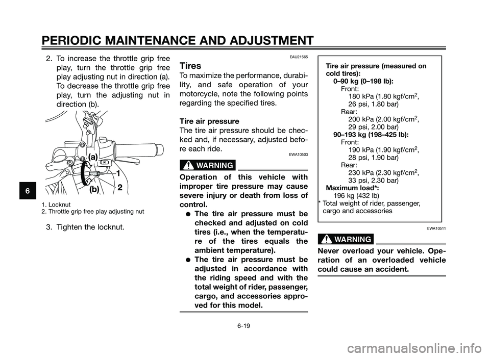
2. To increase the throttle grip freeplay, turn the throttle grip free
play adjusting nut in direction (a).
To decrease the throttle grip free
play, turn the adjusting nut in
direction (b).
1. Locknut
2. Throttle grip free play adjusting nut
3. Tighten the locknut.
EAU21565
Tires
To maximize the performance, durabi-
lity, and safe operation of your
motorcycle, note the following points
regarding the specified tires.
Tire air pressure
The tire air pressure should be chec-
ked and, if necessary, adjusted befo-
re each ride.
EWA10503
Operation of this vehicle with
improper tire pressure may cause
severe injury or death from loss of
control.
�The tire air pressure must be
checked and adjusted on cold
tires (i.e., when the temperatu-
re of the tires equals the
ambient temperature).
�The tire air pressure must be
adjusted in accordance with
the riding speed and with the
total weight of rider, passenger,
cargo, and accessories appro-
ved for this model.
EWA10511
Never overload your vehicle. Ope-
ration of an overloaded vehicle
could cause an accident.
WARNING
Tire air pressure (measured on
cold tires):0–90 kg (0–198 lb): Front:180 kPa (1.80 kgf/cm
2,
26 psi, 1.80 bar)
Rear: 200 kPa (2.00 kgf/cm
2,
29 psi, 2.00 bar)
90–193 kg (198–425 lb): Front:190 kPa (1.90 kgf/cm
2,
28 psi, 1.90 bar)
Rear: 230 kPa (2.30 kgf/cm
2,
33 psi, 2.30 bar)
Maximum load*: 196 kg (432 lb)
* Total weight of rider, passenger, cargo and accessories WARNING
PERIODIC MAINTENANCE AND ADJUSTMENT
6-19
6
1HD-F819D-E0 7/3/11 20:27 Página 56
2AS-F819D-E0.indd 5631/07/12 10:09
Page 57 of 92
Tire inspection
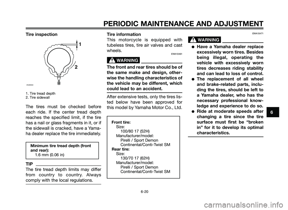
1. Tire tread depth
2. Tire sidewall
The tires must be checked before
each ride. If the center tread depth
reaches the specified limit, if the tire
has a nail or glass fragments in it, or if
the sidewall is cracked, have a Yama-
ha dealer replace the tire immediately.
TIP
The tire tread depth limits may differ
from country to country. Always
comply with the local regulations.
Tire information
This motorcycle is equipped with
tubeless tires, tire air valves and cast
wheels.
EWA10461
The front and rear tires should be of
the same make and design, other-
wise the handling characteristics of
the vehicle may be different, which
could lead to an accident.
After extensive tests, only the tires lis-
ted below have been approved for
this model by Yamaha Motor Co., Ltd.
EWA10471
�Have a Yamaha dealer replace
excessively worn tires. Besides
being illegal, operating the
vehicle with excessively worn
tires decreases riding stability
and can lead to loss of control.
�The replacement of all wheel
and brake-related parts, inclu-
ding the tires, should be left to
a Yamaha dealer, who has the
necessary professional know-
ledge and experience to do so.
�Ride at moderate speeds after
changing a tire since the tire
surface must first be “broken
in” for it to develop its optimal
characteristics.
WARNING
Front tire:Size: 100/80 17 (52H)
Manufacturer/model: Pirelli / Sport Demon
Continental/Conti-Twist SM
Rear tire: Size: 130/70 17 (62H)
Manufacturer/model: Pirelli / Sport Demon
Continental/Conti-Twist SM
WARNING
Minimum tire tread depth (front
and rear):1.6 mm (0.06 in)
1
2
ZAUM0054
PERIODIC MAINTENANCE AND ADJUSTMENT
6-20
6
1HD-F819D-E0 7/3/11 20:27 Página 57
2AS-F819D-E0.indd 5731/07/12 10:09
Page 58 of 92
EAU21962
Cast wheels
To maximize the performance, durabi-
lity, and safe operation of your vehi-
cle, note the following points regar-
ding the specified wheels.
�The wheel rims should be chec-
ked for cracks, bends, warpage
or other damage before each
ride. If any damage is found,
have a Yamaha dealer replace
the wheel. Do not attempt even
the smallest repair to the wheel.
A deformed or cracked wheel
must be replaced.
�The wheel should be balanced
whenever either the tire or wheel
has been changed or replaced.
An unbalanced wheel can result
in poor performance, adverse
handling characteristics, and a
shortened tire life.
EAU22020
Adjusting the clutch lever
free play
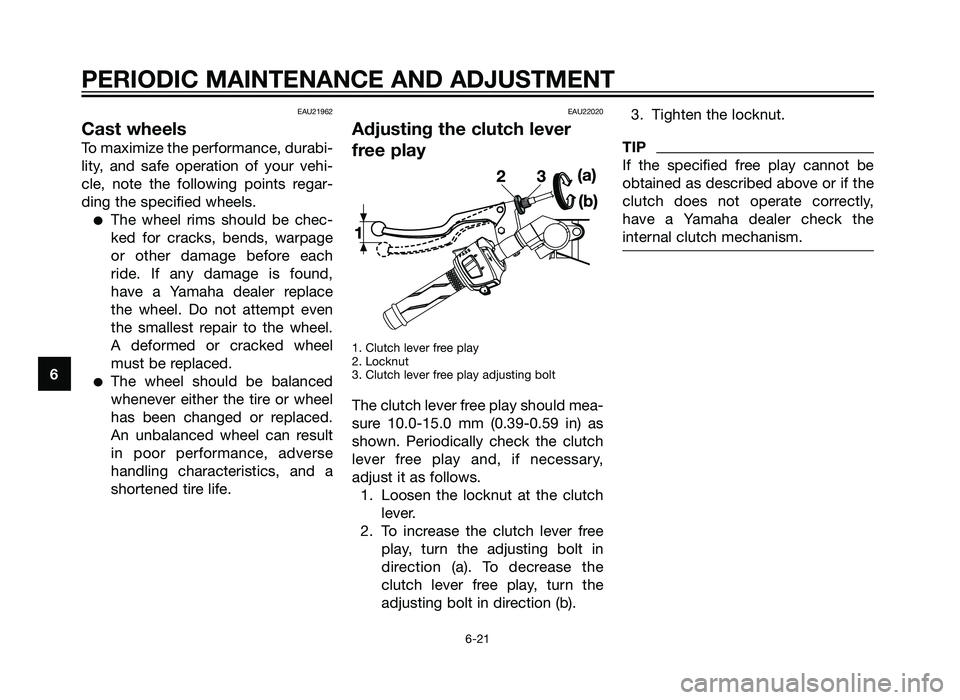
1. Clutch lever free play
2. Locknut
3. Clutch lever free play adjusting bolt
The clutch lever free play should mea-
sure 10.0-15.0 mm (0.39-0.59 in) as
shown. Periodically check the clutch
lever free play and, if necessary,
adjust it as follows.1. Loosen the locknut at the clutch lever.
2. To increase the clutch lever free play, turn the adjusting bolt in
direction (a). To decrease the
clutch lever free play, turn the
adjusting bolt in direction (b). 3. Tighten the locknut.
TIP
If the specified free play cannot be
obtained as described above or if the
clutch does not operate correctly,
have a Yamaha dealer check the
internal clutch mechanism.
PERIODIC MAINTENANCE AND ADJUSTMENT
6-21
6
1HD-F819D-E0 7/3/11 20:27 Página 58
2AS-F819D-E0.indd 5831/07/12 10:09
Page 59 of 92
EAUT1221
Checking the front brake
lever free play
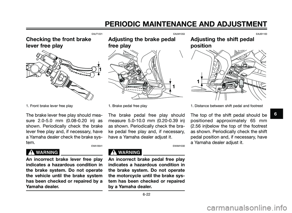
1. Front brake lever free play
The brake lever free play should mea-
sure 2.0-5.0 mm (0.08-0.20 in) as
shown. Periodically check the brake
lever free play and, if necessary, have
a Yamaha dealer check the brake sys-
tem.
EWA10641
An incorrect brake lever free play
indicates a hazardous condition in
the brake system. Do not operate
the vehicle until the brake system
has been checked or repaired by a
Yamaha dealer.
EAUM1353
Adjusting the brake pedal
free play
1. Brake pedal free play
The brake pedal free play should
measure 5.0-10.0 mm (0.20-0.39 in)
as shown. Periodically check the bra-
ke pedal free play and, if necessary,
have a Yamaha dealer adjust it.
EWAM1030
An incorrect brake pedal free play
indicates a hazardous condition in
the brake system. Do not operate
the motorcycle until the brake sys-
tem has been checked or repaired
by a Yamaha dealer.
EAUB1100
Adjusting the shift pedal
position
1. Distance between shift pedal and footrest
The top of the shift pedal should be
positioned approximately 65 mm
(2.56 in)below the top of the footrest
as shown. Periodically check the shift
pedal position and, if necessary, have
a Yamaha dealer adjust it.
WARNINGWARNING
PERIODIC MAINTENANCE AND ADJUSTMENT
6-22
6
1HD-F819D-E0 7/3/11 20:27 Página 59
2AS-F819D-E0.indd 5931/07/12 10:09
Page 60 of 92
EAU22273
Brake light switches
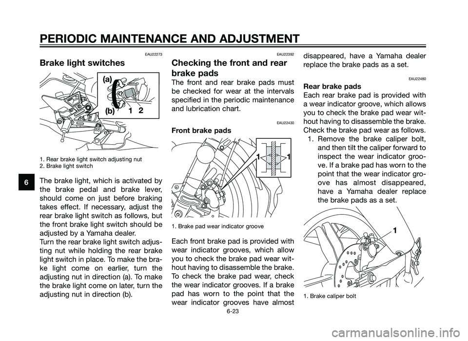
1. Rear brake light switch adjusting nut
2. Brake light switch
The brake light, which is activated by
the brake pedal and brake lever,
should come on just before braking
takes effect. If necessary, adjust the
rear brake light switch as follows, but
the front brake light switch should be
adjusted by a Yamaha dealer.
Turn the rear brake light switch adjus-
ting nut while holding the rear brake
light switch in place. To make the bra-
ke light come on earlier, turn the
adjusting nut in direction (a). To make
the brake light come on later, turn the
adjusting nut in direction (b).
EAU22392
Checking the front and rear
brake pads
The front and rear brake pads must
be checked for wear at the intervals
specified in the periodic maintenance
and lubrication chart.
EAU22430
Front brake pads
1. Brake pad wear indicator groove
Each front brake pad is provided with
wear indicator grooves, which allow
you to check the brake pad wear wit-
hout having to disassemble the brake.
To check the brake pad wear, check
the wear indicator grooves. If a brake
pad has worn to the point that the
wear indicator grooves have almostdisappeared, have a Yamaha dealer
replace the brake pads as a set.
EAU22480
Rear brake pads
Each rear brake pad is provided with
a wear indicator groove, which allows
you to check the brake pad wear wit-
hout having to disassemble the brake.
Check the brake pad wear as follows.
1. Remove the brake caliper bolt, and then tilt the caliper forward to
inspect the wear indicator groo-
ve. If a brake pad has worn to the
point that the wear indicator gro-
ove has almost disappeared,
have a Yamaha dealer replace
the brake pads as a set.
1. Brake caliper bolt
PERIODIC MAINTENANCE AND ADJUSTMENT
6-23
6
1HD-F819D-E0 7/3/11 20:27 Página 60
2AS-F819D-E0.indd 6031/07/12 10:09