YAMAHA WR 450F 2005 Owners Manual
Manufacturer: YAMAHA, Model Year: 2005, Model line: WR 450F, Model: YAMAHA WR 450F 2005Pages: 758, PDF Size: 17.3 MB
Page 701 of 758

–+ELEC
4. Einstellen:
Leerlaufdrehzahl
Siehe unter “LEERLAUF-
DREHZAHL EINSTELLEN” in
KAPITEL 3.
5. Dünne Leiter (Kabel) 2, wie in
der Abbildung gezeigt, in den
Drosselklappensensor-Steckver-
binder 1 stecken und das Meß-
gerät daran anschließen.
ACHTUNG:
Die elektrischen Leiter nicht tie-
fer als notwendig in den Steck-
verbinder stecken, um dessen
Wasserdichtigkeit nicht zu
beeinträchtigen.
Darauf achten, daß kein Kurz-
schluß vorliegt, um eine
Beschädigung der elektrischen
Anlage zu vermeiden.
6. Den Motor starten.Meßkabel (+) → Gelb 3
Meßkabel (–) → Schwarz 4
7. Einstellen:
Drosselklappensensor-Aus-
gangsspannung
Arbeitsvorgang:
Den Einbauwinkel des Drossel-
klappensensors 1 so einstellen,
daß die vorgeschriebene Aus-
gangsspannung anliegt.
HINWEIS:
Die Ausgangsspannung muß mit
einem präzisen Digitalmeßgerät
erfaßt werden.
Drosselklappen-
sensor-Aus-
gangsspannungMeßgerät-
Wahlschalter
0,58–0,78 V DCV
4. Régler:
Ralenti
Se reporter à la section
“REGLAGE DU REGIME DE
RALENTI” au CHAPITRE 3.
5. Introduire les fins conducteurs élec-
triques 2 (fil) dans la fiche rapide
du TPS 1, comme illustré, et y rac-
corder le multimètre.
ATTENTION:
Ne pas enfoncer les conducteurs
électriques plus que nécessaire
parce que cela risque de réduire
l’étanchéité de la fiche rapide.
Veiller à ce qu’aucun court-circuit
ne se produise entre les bornes car
cela risque d’endommager les com-
posants électriques.
6. Mettre le moteur en marche.Fil (+) du multimètre → fil jaune 3
Fil (–) du multimètre → fil noir 4
7. Régler:
Tension de sortie du TPS
Etapes du réglage:
Régler l’angle de montage du TPS 1
de manière à obtenir la tension de
sortie spécifiée.
N.B.:
Mesurer avec précision la tension de
sortie à l’aide d’un voltmètre électro-
nique permettant une lecture facile
des faibles tensions.
Tension de
sortie du TPSPosition du
sélecteur du
multimètre
0,58 à 0,78 V DCV
4. Ajustar:
Ralentí
Consulte el apartado “AJUSTE
DEL RALENTÍ DEL MOTOR”
del CAPÍTULO 3.
5. Introduzca los conductores eléctri-
cos finos 2 (cable) en el acoplador
del TPS 1, como se muestra, y
conecte el comprobador.
ATENCION:
No introduzca los conductores eléc-
tricos más de lo necesario, pues se
puede reducir la estanqueidad del
acoplador.
Verifique que no se desarrolle un
cortocircuito entre los terminales;
ello podría provocar daños en los
componentes eléctricos.
6. Arranque el motor.Cable (+) del comprobador →
Cable amarillo 3
Cable (–) del comprobador →
Cable negro 4
7. Ajustar:
Voltaje de salida del TPS
Procedimiento de ajuste:
Ajuste el ángulo del TPS 1 hasta
obtener el voltaje de salida especifi-
cado.
NOTA:
Mida con precisión el voltaje de
salida con un voltímetro electrónico y
digital que proporcione una lectura
fácil de voltajes pequeños.
Voltaje de
salida del TPS Posición del
selector del
comprobador
0,58 ~ 0,78 V DCV
SYSTEME TPS (CAPTEUR DE POSITION DE PAPILLON DES GAZ)
DROSSELKLAPPENSENSOR
SISTEMA TPS (SENSOR DE POSICIÓN DEL ACELERADOR)
6 - 22
Page 702 of 758

6 - 23
–+ELECTPS (THROTTLE POSITION SENSOR) SYSTEM
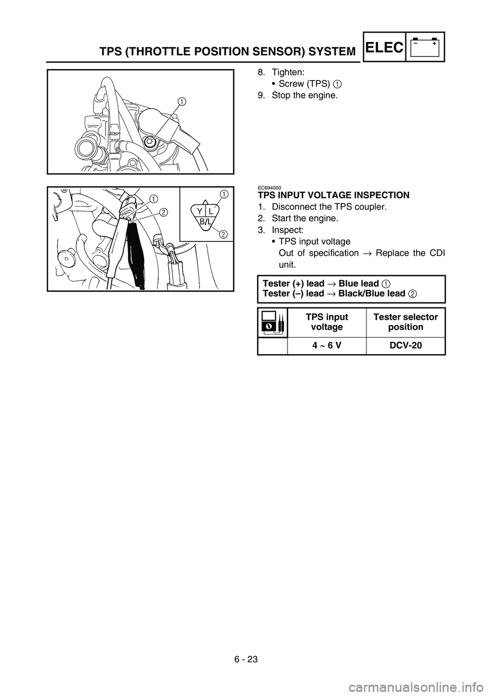
8. Tighten:
Screw (TPS) 1
9. Stop the engine.
1
EC694000
TPS INPUT VOLTAGE INSPECTION
1. Disconnect the TPS coupler.
2. Start the engine.
3. Inspect:
TPS input voltage
Out of specification → Replace the CDI
unit.
Tester (+) lead
→ Blue lead
1
Tester (–) lead
→ Black/Blue lead
2
TPS input
voltageTester selector
position
4 ~ 6 V DCV-20
Page 703 of 758

–+ELEC
8. Festziehen:
Drosselklappensensor-
Schraube 1
9. Den Motor abstellen.
DROSSELKLAPPENSENSOR-
EINGANGSSPANNUNG
KONTROLLIEREN
1. Den Drosselklappensensor-
Steckverbinder abziehen.
2. Den Motor starten.
3. Kontrollieren:
Drosselklappensensor-Ein-
gangsspannung
Nicht nach Vorgabe → Zünd-
box erneuern.
Meßkabel (+) → Blau 1
Meßkabel (–) →
Schwarz/Blau 2
Drosselklappen-
sensor-Ein-
gangsspannungMeßgerät-
Wahlschalter
4–6 V DCV-20
8. Serrer:
Vis (TPS) 1
9. Arrêter le moteur.
CONTROLE DE LA TENSION
D’ENTREE DU TPS
1. Débrancher la fiche rapide du TPS.
2. Mettre le moteur en marche.
3. Contrôler:
Tension d’entrée du TPS
Hors spécifications → Remplacer
le boîtier CDI.
Fil (+) du multimètre → fil bleu 1
Fil (–) du multimètre →
fil noir/bleu 2
Tension
d’entrée du
TPSPosition du
sélecteur du
multimètre
4 à 6 V DCV-20
8. Apretar:
Tornillo (TPS) 1
9. Pare el motor.
COMPROBACIÓN DEL VOLTAJE
DE ENTRADA DEL TPS
1. Desconecte el acoplador del TPS.
2. Arranque el motor.
3. Comprobar:
Voltaje de entrada del TPS
Fuera del valor especificado →
Cambiar la unidad CDI.
Cable (+) del comprobador →
Cable azul 1
Cable (–) del comprobador →
Cable negro/azul 2
Voltaje de
entrada del
TPS Posición del
selector del
comprobador
4 ~ 6 V DCV-20
SYSTEME TPS (CAPTEUR DE POSITION DE PAPILLON DES GAZ)
DROSSELKLAPPENSENSOR
SISTEMA TPS (SENSOR DE POSICIÓN DEL ACELERADOR)
6 - 23
Page 704 of 758

–+ELEC
6 - 24
LIGHTING SYSTEM
LIGHTING SYSTEM
INSPECTION STEPS
Refer to the following flow chart when inspecting the ignition system for possible problems.
NOTE:
Replace the bulb and/or bulb socket.
1) Seat
2) Fuel tank
Use the following special tool.
Check the bulb and bulb
socket.Replace the bulb and/
or bulb socket.
Check the AC magneto. Lighting coil Replace.
Check the entire lighting
system proper for connec-
tions.Repair or replace.
Check the rectifier/regulator.Out-put
voltageReplace.
Pocket tester:
YU-3112-C/90890-03112
OK
OK
OK
No good
Improperly connectedNo good
No good
Page 705 of 758

–+ELEC
ECLAIRAGE
ETAPES DU CONTROLE
Se reporter au diagramme suivant pour le contrôle du système d’allumage.
N.B.:
Remplacer l’ampoule et/ou la douille.
1) Selle
2) Réservoir de carburant
Utiliser l’outil spécial suivant.
Contrôler l’ampoule et sa
douille.Remplacer l’ampoule et/
ou la douille.
Contrôler l’alternateur avec
rotor à aimantation perma-
nente.Bobine d’éclai-
rageRemplacer.
Contrôler toutes les con-
nexions du circuit d’éclairage.Réparer ou remplacer.
Contrôler le redresseur/régula-
teur.Tension de sor-
tieRemplacer.
Multimètre:
YU-3112-C/90890-03112
OK
OK
OK
ECLAIRAGE
6 - 24
Problème
Mauvaise connexionProblème
Problème
Page 706 of 758

–+ELEC
BELEUCHTUNGSANLAGE
KONTROLLE
Folgende Prüfschritte dienen zur Diagnose von Problemen in der Beleuchtungsanlage.
HINWEIS:
Lampe und/oder Lampenfassung erneuern.
1) Sitzbank
2) Kraftstofftank
Folgendes Spezialwerkzeug verwenden.
Lampen und Lampenfas-
sungen kontrollieren.Lampe und/oder Lam-
penfassung erneuern.
Lichtmaschine kontrollieren. Lichtspule Erneuern.
Kabelanschlüsse der
gesamten Beleuchtungsan-
lage kontrollieren.Instand setzen, ggf.
erneuern.
Gleichrichter/Regler kontrol-
lieren.Ausgangs-
spannungErneuern.
Taschen-Multimeter:
YU-3112-C/90890-03112
In Ordnung
In Ordnung
In Ordnung
BELEUCHTUNGSANLAGE
6 - 24
Nicht in Ordnung
Lose VerbindungNicht in Ordnung
Nicht in Ordnung
Page 707 of 758

–+ELEC
SISTEMA DE ILUMINACIÓN
PROCEDIMIENTO DE REVISIÓN
Consulte el diagrama de flujo siguiente cuando compruebe posibles fallos del sistema de encendido.
NOTA:
Cambiar la bombilla o el casquillo de la bombilla.
1) Sillín
2) Depósito de combustible
Utilice la herramienta especial siguiente.
Comprobar la bombilla y el
casquillo de la bombilla.Cambiar la bombilla o el
casquillo de la bombilla.
Comprobar la magneto CA.Bobina de ilu-
minaciónCambiar.
Comprobar las conexiones del
sistema de iluminación.Reparar o cambiar.
Comprobar el rectificador/
regulador.Voltaje de
salidaCambiar.
Comprobador de bolsillo:
YU-3112-C/90890-03112
Correcto
Correcto
Correcto
SISTEMA DE ILUMINACIÓN
6 - 24
Incorrecto
Conexión incorrectaIncorrecto
Incorrecto
Page 708 of 758

6 - 25
–+ELECLIGHTING SYSTEM
AC MAGNETO INSPECTION
1. Inspect:
Lighting coil resistance
Out of specification → Replace.
RECTIFIER/REGULATOR INSPECTION
1. Connect the battery leads.
2. Start the engine.
3. Turn on the headlight and taillight by turn-
ing on the lights switch.
4. Inspect:
Out-put voltage
Out of specification → Replace rectifier/
regulator. Tester (+) lead
→ Yellow lead
1
Tester (–) lead
→ Ground
2
Lighting coil
resistanceTester selector
position
0.224 ~ 0.336
Ω
at 20 °C (68 °F)Ω
× 1
Tester (+) lead
→ Yellow lead
1
Tester (–) lead
→ Black lead
2
Out-put voltageTester selector
position
13.0 ~ 14.0 V at
5,000 r/minACV-20
R
BW
Y1
2
Page 709 of 758

–+ELEC
LICHTMASCHINE
KONTROLLIEREN
1. Kontrollieren:
Lichtspulen-Widerstand
Nicht nach Vorgabe → Erneu-
ern.
GLEICHRICHTER/REGLER
KONTROLLIEREN
1. Die Batteriekabel anschließen.
2. Den Motor starten.
3. Mit dem Lichtschalter den
Scheinwerfer und das Rücklicht
einschalten.
4. Kontrollieren:
Ausgangsspannung
Nicht nach Vorgabe → Gleich-
richter/Regler erneuern. Meßkabel (+) → Gelb 1
Meßkabel (–) → Masse 2
Lichtspulen-
WiderstandMeßgerät-
Wahlschalter
0,224–
0,336 Ω bei
20 °C (68 °F)Ω × 1
Meßkabel (+) → Gelb 1
Meßkabel (–) → Schwarz 2
Ausgangs-
spannungMeßgerät-
Wahlschalter
13,0–14,0 V
bei
5.000 U/minACV-20
CONTROLE DE L’ALTERNATEUR
AVEC ROTOR A AIMENTATION
PERMANENTE
1. Contrôler:
Résistance de la bobine d’éclai-
rage
Hors spécifications → Rempla-
cer.
CONTROLE DU REDRESSEUR/
REGULATEUR
1. Raccorder les câbles de la batterie.
2. Mettre le moteur en marche.
3. Allumer le phare et le feu arrière à
l’aide du contacteur d’éclairage.
4. Contrôler:
Tension de sortie
Hors spécifications → Remplacer
le redresseur/régulateur. Fil (+) du multimètre → fil jaune 1
Fil (–) du multimètre → terre 2
Résistance de
la bobine
d’éclairagePosition du
sélecteur du
multimètre
0,224 à
0,336 Ω à
20 °C (68 °F)Ω × 1
Fil (+) du multimètre → fil jaune 1
Fil (–) du multimètre → fil noir 2
Tension de
sortiePosition du
sélecteur du
multimètre
13,0 à
14,0 V à
5.000 tr/minACV-20
COMPROBACIÓN DE LA
MAGNETO CA
1. Comprobar:
Resistencia de la bobina de luz
Fuera del valor especificado →
Cambiar.
COMPROBACIÓN DEL
RECTIFICADOR/REGULADOR
1. Conectar los cables de la batería.
2. Arranque el motor.
3. Encienda el faro y el piloto trasero
con el interruptor de luces.
4. Comprobar:
Voltaje de salida
Fuera del valor especificado →
Cambiar el rectificador/regula-
dor. Cable (+) del comprobador →
Cable amarillo 1
Cable (–) del comprobador →
Masa 2
Resistencia de
la bobina de
luzPosición del
selector del
comprobador
0,224 ~
0,336 Ω a
20 °C (68 °F)Ω × 1
Cable (+) del comprobador →
Cable amarillo 1
Cable (–) del comprobador →
Cable negro 2
Voltaje de
salidaPosición del
selector del
comprobador
13,0 ~ 14,0 V
a 5.000 r/minACV-20
ECLAIRAGE
BELEUCHTUNGSANLAGE
SISTEMA DE ILUMINACIÓN
6 - 25
Page 710 of 758

7 - 1
TUN
EC700000
TUNING
EC710000
ENGINE
Carburetor setting
The air/fuel mixture will vary depending on
atmospheric conditions. Therefore, it is nec-
essary to take into consideration the air pres-
sure, ambient temperature, humidity, etc.,
when adjusting the carburetor.
Perform a test run to check for proper engine
performance (e.g., throttle response) and
spark plug(-s) discoloration or fouling. Use
these readings to determine the best possi-
ble carburetor setting.
NOTE:
It is recommended to keep a record of all car-
buretor settings and external conditions (e.g.,
atmospheric conditions, track/surface condi-
tions, lap times) to make future carburetor set-
ting easier.
WARNING
The carburetor is a part of the fuel line.
Therefore, be sure to install it in a well-
ventilated area, away from flammable
objects and any sources of fire.
Never look into the carburetor intake.
Flames may shoot out from the pipe if the
engine backfires while it is being started.
Gasoline may be discharged from the
accelerator pump nozzle when the carbu-
retor has been removed.
SETTING