YAMAHA WR 450F 2006 Owners Manual
Manufacturer: YAMAHA, Model Year: 2006, Model line: WR 450F, Model: YAMAHA WR 450F 2006Pages: 786, PDF Size: 22.49 MB
Page 171 of 786
2 - 21
SPEC
SCHMIERSYSTEM-
SCHAUBILDER
1Ölzufuhrleitung
2Einlass-Nockenwelle
3Auslass-Nockenwelle
4Ölfiltereinsatz
5Ölpumpe
6Eingangswelle
7Ausgangswelle
DIAGRAMMES DE
LUBRIFICATION
1Tuyau d’amenée d’huile
2Arbre à cames d’admission
3Arbre à cames d’échappement
4Elément de filtre à huile
5Pompe à huile
6Arbre primaire
7Arbre secondaire
DIAGRAMAS DE
ENGRASE
1Tubería de suministro de aceite
2Eje de levas de admisión
3Eje de levas de escape
4Elemento del depurador de aceite
5Bomba de aceite
6Eje principal
7Eje posterior
DIAGRAMMES DE LUBRIFICATION
SCHMIERSYSTEM-SCHAUBILDER
DIAGRAMAS DE ENGRASE
Page 172 of 786
2 - 22
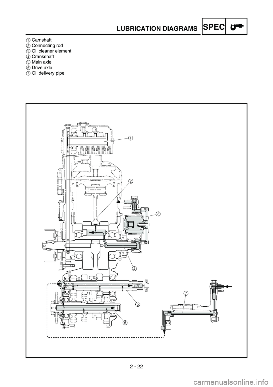
SPECLUBRICATION DIAGRAMS
1Camshaft
2Connecting rod
3Oil cleaner element
4Crankshaft
5Main axle
6Drive axle
7Oil delivery pipe
Page 173 of 786
2 - 22
SPEC
1Nockenwelle
2Übertragungshebel
3Ölfiltereinsatz
4Kurbelwelle
5Eingangswelle
6Ausgangswelle
7Ölzufuhrleitung 1Arbre à cames
2Bielle
3Elément de filtre à huile
4Vilebrequin
5Arbre primaire
6Arbre secondaire
7Tuyau d’amenée d’huile1Eje de levas
2Biela
3Elemento del depurador de aceite
4Cigüeñal
5Eje principal
6Eje posterior
7Tubería de suministro de aceite
DIAGRAMMES DE LUBRIFICATION
SCHMIERSYSTEM-SCHAUBILDER
DIAGRAMAS DE ENGRASE
Page 174 of 786

2 - 23
SPECCABLE ROUTING DIAGRAM
EC240000
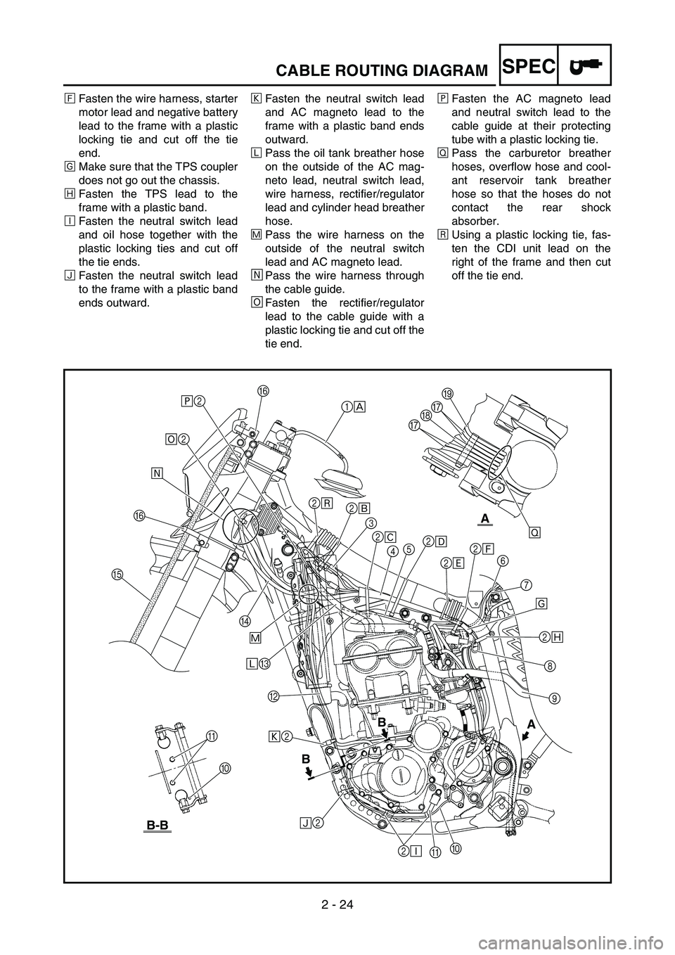
CABLE ROUTING DIAGRAM
1Fuel tank breather hose
2Clamp
3Diode
4Wire harness
5Hot starter cable
6Negative battery lead
7Starter motor lead
8TPS (throttle position sensor)
lead
9Cylinder head breather hose
0Neutral switch lead
AOil hose
BAC magneto lead
COil tank breather hose
DRectifier/regulator lead
EBrake hose
FHose guideGCarburetor breather hose
HOverflow hose
ICoolant reservoir tank breather
hose
ÈInsert the fuel tank breather
hose into the hole in the steer-
ing shaft cap.
ÉUsing a plastic locking tie and
fasten the diode of the wire har-
ness (at the white tape) to the
frame, and cut off the tie end.ÊFasten the wire harness, cool-
ant reservoir hose and hot
starter cable to the frame with a
plastic locking tie and cut off the
tie end.
ËFasten the wire harness and
coolant reservoir hose to the
frame with a plastic locking tie
and cut off the tie end.
ÌFasten the wire harness to the
frame at its white tape with a
plastic locking tie and cut off the
tie end.
2
Ù
B
BA
B-B
A
A
0Ò2
Ñ2 B ÓC Ô D
EFÕÖ2
×2F
1
È
2
É
3
2
Ê
452
Ë
2
Ì2
Í
6
7
Î
2
Ï
8
9
0
A 2
ÐØ GG
HI
Page 175 of 786

2 - 23
SPEC
KABELFÜHRUNGSDIA-
GRAMME
1Kraftstofftank-Belüftungsschlauch
2Kabelbinder
3Diode
4Kabelbaum
5Warmstartzug
6Batterie-Minuskabel
7Starter-Kabel
8Drosselklappensensor-Kabel
9Zylinderkopf-Entlüftungsschlauch
0Leerlaufschalter-Kabel
AÖlschlauch
BLichtmaschinen-Kabel
CÖltank-Belüftungsschlauch
DGleichrichter/Regler-Kabel
EBremsschlauch
FSchlauchführung
GVergaser-Entlüftungsschlauch
HÜberlaufschlauch
IAusgleichsbehälter-Entlüftungs-
schlauch
ÈDen Kraftstofftank-Belüftungsschlauch
durch die Bohrung in der Lenkkopf-
Abdeckung stecken.
ÉDie Kabelbaum-Diode an der mit
einem weißen Band markierten Stelle
mit einem Kabelbinder am Rahmen
befestigen und das Ende des Kabel-
binders abschneiden.
ÊDen Kabelbaum, den Ausgleichsbe-
hälter-Schlauch und den Warmstart-
zug mit einem Kabelbinder am
Rahmen befestigen und das Ende
des Binders abschneiden.
ËDen Kabelbaum und den Ausgleichs-
behälter-Schlauch mit einem Kabel-
binder am Rahmen befestigen und
das Ende des Binders abschneiden.
ÌDen Kabelbaum an der mit weißem
Band markierten Stelle mit einem
Kabelbinder am Rahmen befestigen
und das Ende des Binders abschnei-
den.
DIAGRAMME
D’ACHEMINEMENT DES
CABLES
1Durit de mise à l’air du réservoir de car-
burant
2Collier à pince
3Diode
4Faisceau de fils
5Câble de démarrage à chaud
6Câble négatif de batterie
7Fil du démarreur
8Fil du capteur de position de papillon des
gaz
9Durit de mise à l’air de la culasse
0Fil du contacteur de point mort
ADurit d’huile
BFil de l’alternateur avec rotor à aimanta-
tion permanente
CDurit de mise à l’air du réservoir d’huile
DFil du redresseur/régulateur
EDurit de frein
FGuide de durit
GDurit de mise à l’air du carburateur
HDurit de trop-plein
IDurit de mise à l’air du vase d’expansion
ÈInsérer la durit de mise à l’air du réservoir
de carburant dans le trou du capuchon de
l’arbre de direction.
ÉA l’aide d’un collier en plastique, serrer la
diode du faisceau de fils (au niveau de
l’adhésif blanc) sur le cadre et couper
l’extrémité du collier.
ÊAttacher le faisceau de fils, la durit du
vase d’expansion et le câble de démarrage
à chaud au cadre à l’aide d’un collier en
plastique et couper l’extrémité du collier.
ËAttacher le faisceau de fils et la durit du
vase d’expansion au cadre à l’aide d’un
collier en plastique et couper l’extrémité
du collier.
ÌFixer le faisceau de fils au cadre au
niveau de la bande blanche à l’aide d’un
collier en plastique et couper l’extrémité
du collier.
DIAGRAMA DE
CABLEADO
1Tubo respiradero del depósito de combus-
tible
2Brida
3Diodo
4Mazo de cables
5Cable de arranque en caliente
6Cable negativo de la batería
7Cable del motor de arranque
8Cable del TPS (sensor de posición del
acelerador)
9Tubo respiradero de la culata
0Cable del interruptor de luz de punto
muerto
ATubo de aceite
BCable de la magneto CA
CTubo respiradero del depósito de aceite
DCable del rectificador/regulador
ETubo de freno
FGuía de tubo
GTubo respiradero del carburador
HTubo de desbordamiento
ITubo respiradero del depósito de refrige-
rante
ÈIntroduzca el tubo respiradero del depó-
sito de combustible por el orificio de la
tapa del eje de la dirección.
ÉSujete el diodo del mazo de cables al bas-
tidor (en la cinta blanca) con una abraza-
dera de plástico y corte el extremo de esta.
ÊSujete el mazo de cables, el tubo del
depósito de refrigerante y el cable de
arranque en caliente al bastidor con una
abrazadera de plástico y corte el extremo
de esta.
ËSujete el mazo de cables y el tubo del
depósito de refrigerante al bastidor con
una abrazadera de plástico y corte el
extremo de esta.
ÌSujete el mazo de cables al bastidor en su
cinta blanca con una abrazadera de plás-
tico y corte el extremo de esta.
DIAGRAMME D’ACHEMINEMENT DES CABLES
KABELFÜHRUNGSDIAGRAMME
DIAGRAMA DE CABLEADO
Page 176 of 786
2 - 24
SPECCABLE ROUTING DIAGRAM
ÍFasten the wire harness, starter
motor lead and negative battery
lead to the frame with a plastic
locking tie and cut off the tie
end.
ÎMake sure that the TPS coupler
does not go out the chassis.
ÏFasten the TPS lead to the
frame with a plastic band.
ÐFasten the neutral switch lead
and oil hose together with the
plastic locking ties and cut off
the tie ends.
ÑFasten the neutral switch lead
to the frame with a plastic band
ends outward.ÒFasten the neutral switch lead
and AC magneto lead to the
frame with a plastic band ends
outward.
ÓPass the oil tank breather hose
on the outside of the AC mag-
neto lead, neutral switch lead,
wire harness, rectifier/regulator
lead and cylinder head breather
hose.
ÔPass the wire harness on the
outside of the neutral switch
lead and AC magneto lead.
ÕPass the wire harness through
the cable guide.
ÖFasten the rectifier/regulator
lead to the cable guide with a
plastic locking tie and cut off the
tie end.×Fasten the AC magneto lead
and neutral switch lead to the
cable guide at their protecting
tube with a plastic locking tie.
ØPass the carburetor breather
hoses, overflow hose and cool-
ant reservoir tank breather
hose so that the hoses do not
contact the rear shock
absorber.
ÙUsing a plastic locking tie, fas-
ten the CDI unit lead on the
right of the frame and then cut
off the tie end.
2
Ù
B
BA
B-B
A
A
0Ò2
Ñ2 B ÓC Ô D
EFÕÖ2
×2F
1
È
2
É
3
2
Ê
452
Ë
2
Ì2
Í
6
7
Î
2
Ï
8
9
0
A 2
ÐØ GG
HI
Page 177 of 786

2 - 24
SPEC
ÍDen Kabelbaum, das Starter-Kabel
und das Batterie-Minuskabel mit
einem Kabelbinder am Rahmen
befestigen und das Ende des Binders
abschneiden.
ÎSicherstellen, dass der Drosselklap-
pensensor-Steckverbinder nicht am
Fahrgestell herausragt.
ÏDas Drosselklappensensor-Kabel mit
einem Kunststoffbinder am Rahmen
befestigen.
ÐDas Leerlaufschalter-Kabel und den
Ölschlauch mit Kabelbindern zusam-
menbinden und die Enden abschnei-
den.
ÑDas Leerlaufschalter-Kabel mit einem
Kunststoffbinder am Rahmen befesti-
gen.
ÒDas Leerlaufschalter-Kabel und das
Lichtmaschinen-Kabel mit einem
Kunststoffbinder am Rahmen befesti-
gen.
ÓDen Öltank-Belüftungsschlauch über
die Lichtmaschinen- und Leerlauf-
schalter-Kabel, den Kabelbaum, das
Gleichrichter/Regler-Kabel und den
Zylinderkopf-Entlüftungsschlauch füh-
ren.
ÔDen Kabelbaum über die Lichtmaschi-
nen- und Leerlaufschalter-Kabel füh-
ren.
ÕDen Kabelbaum durch die Kabelfüh-
rung leiten.
ÖDas Gleichrichter/Regler-Kabel mit
einem Kabelbinder an der Kabelfüh-
rung befestigen und das Ende des
Binders abschneiden.
×Die Lichtmaschinen- und Leerlauf-
schalter-Kabel an deren Schutzhüllen
mit einem Kabelbinder an der Kabel-
führung befestigen.
ØDie Vergaser-Belüftungs- und Über-
lauf- sowie Ausgleichsbehälter-Entlüf-
tungsschläuche so führen, dass sie
das Federbein nicht berühren.
ÙDas Zündboxkabel mit einem Kabel-
binder auf der rechten Seite des Rah-
mens befestigen und dann das Ende
des Binders abschneiden. ÍAttacher le faisceau de fils, le fil du
moteur de démarreur et le fil négatif de la
batterie au cadre à l’aide d’un collier en
plastique et couper l’extrémité du collier.
ÎVeiller à ce que la fiche rapide du capteur
de position de papillon des gaz ne sorte
pas du châssis.
ÏFixer le fil du capteur de position de
papillon des gaz au cadre à l’aide d’un
collier réutilisable.
ÐAttacher le fil du contacteur de point mort
et la durit d’huile à l’aide des colliers en
plastique et couper les extrémités des col-
liers.
ÑFixer le fil du contacteur de point mort au
cadre à l’aide des extrémités de la bande
en plastique tournées vers l’extérieur.
ÒFixer le fil du contacteur de point mort et
le fil de l’alternateur au cadre à l’aide des
extrémités de la bande en plastiques tour-
nés vers l’extérieur.
ÓAcheminer la durit de mise à l’air du
réservoir d’huile à l’extérieur du fil de
l’alternateur avec rotor à aimantation per-
manente, du fil de contacteur de point
mort, du faisceau de fils, du fil du redres-
seur/régulateur et de la durit de mise à
l’air de la culasse.
ÔAcheminer le faisceau de fils à l’extérieur
du fil du contacteur de point mort et du fil
de l’alternateur avec rotor à aimantation
permanente.
ÕAcheminer le faisceau de fils dans le
guide-câble.
ÖFixer le fil du redresseur/régulateur au
cadre à l’aide d’un collier en plastique et
couper l’extrémité du collier.
×Fixer le fil de l’alternateur et le fil du con-
tacteur de point mort au guide-câbles au
niveau de leur tube de protection, à l’aide
d’un collier en plastique.
ØAcheminer les durits de mise à l’air du
carburateur, la durit de trop-plein et la
durit de mise à l’air du vase d’expansion
de manière que les durits n’entrent pas en
contact avec l’amortisseur arrière.
ÙA l’aide d’un collier en plastique, serrer le
fil de l’unité CDI à droite du cadre, puis
couper l’extrémité du collier.ÍSujete el mazo de cables, el cable del
motor de arranque y el cable negativo de
la batería al bastidor con una abrazadera
de plástico y corte el extremo de esta.
ÎVerifique que el acoplador del TPS no se
salga del chasis.
ÏSujete el cable del TPS al bastidor con
una banda de plástico.
ÐSujete el cable del interruptor de luz de
punto muerto y el tubo de aceite juntos
con las abrazaderas de plástico y corte los
extremos de estas.
ÑSujete el cable del interruptor de luz de
punto muerto al bastidor con una banda
de plástico, los extremos hacia afuera.
ÒSujete el cable del interruptor de luz de
punto muerto y el cable de la magneto CA
al bastidor con una banda de plástico, los
extremos hacia afuera.
ÓPase el tubo respiradero del depósito de
aceite por fuera del cable de la magneto
CA, del cable del interruptor de luz de
punto muerto, del mazo de cables, del
cable del rectificador/regulador y del tubo
respiradero de la culata.
ÔPase el mazo de cables por el exterior del
cable del interruptor de luz de punto
muerto y del cable de la magneto CA.
ÕPase el mazo de cables por la guía.
ÖSujete el cable del rectificador/regulador
a la guía del cable con una abrazadera de
plástico y corte el extremo de esta.
×Sujete el cable de la magneto CA y el
cable del interruptor de luz de punto
muerto a la guía del cable en su tubo pro-
tector con una abrazadera de plástico.
ØPase los tubos respiraderos del carbura-
dor, el tubo de rebosamiento y el tubo res-
piradero del depósito de refrigerante de
forma que no toquen el amortiguador tra-
sero.
ÙSujete el cable de la unidad CDI al lado
derecho del bastidor con una abrazadera
de plástico y corte el extremo de esta.
DIAGRAMME D’ACHEMINEMENT DES CABLES
KABELFÜHRUNGSDIAGRAMME
DIAGRAMA DE CABLEADO
Page 178 of 786

2 - 25
SPECCABLE ROUTING DIAGRAM
1Hot starter cable
2Clutch cable
3Throttle cable (return)
4Throttle cable (pull)
5Ignition coil
6Negative battery lead
7Starter motor lead
8Coolant reservoir tank breather
hose
9Cable holder
0Coolant reservoir hose
AClamp
BCDI unit lead
CCDI unit
DCDI unit band
ECDI unit stay (frame)
FCable bracketÈPass the throttle cables, clutch
cable and hot starter cable
through the cable guides.
ÉPass the throttle cables, clutch
cable and hot starter cable
between the radiator and frame,
then over the middle radiator
mounting boss.
ÊPass the throttle cables and
clutch cable on the outside of
the ignition coil.
ËPass the carburetor breather
hose (throttle cable cover)
through the hose holder.
ÌFasten the coolant reservoir
tank breather hose and carbure-
tor breather hoses together with
a plastic locking tie.ÍFasten the grommet of the clutch
cable with the cable holder.
ÎFasten the CDI unit lead to the
frame with a plastic locking tie
ends at the lower of the frame
and cut off the tie end.
ÏInsert the CDI unit band over the
CDI unit stay (frame) as far as
possible.
ÐFasten the starter motor lead
and negative battery lead to the
cable bracket in its slot with a
plastic locking tie and cut off the
tie end.
A
A
D
ÏE A
Ð
B
B
C
F
Í90
ÎABCD
1
2
43
È
É
Ê
5
6 7 8 Ë Ì
Page 179 of 786
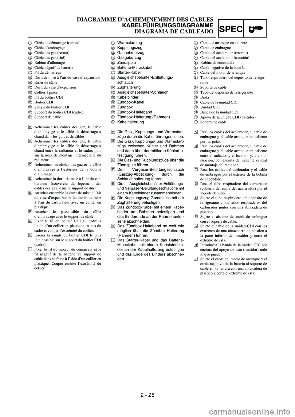
2 - 25
SPEC
1Warmstartzug
2Kupplungszug
3Gasnehmerzug
4Gasgeberzug
5Zündspule
6Batterie-Minuskabel
7Starter-Kabel
8Ausgleichsbehälter-Entlüftungs-
schlauch
9Zughalterung
0Ausgleichsbehälter-Schlauch
AKabelbinder
BZündbox-Kabel
CZündbox
DZündbox-Halteband
EZündbox-Halterung (Rahmen)
FKabelhalterung
ÈDie Gas-, Kupplungs- und Warmstart-
züge durch die Kabelführungen leiten.
ÉDie Gas-, Kupplungs- und Warmstart-
züge zwischen Kühler und Rahmen
und dann über der mittleren Kühlerbe-
festigung führen.
ÊDie Gas- und Kupplungszüge über die
Zündspule führen.
ËDen Vergaser-Belüftungsschlauch
(Gaszug-Abdeckung) durch die
Schlauchhalterung führen.
ÌDie Ausgleichsbehälter-Entlüftungs-
und Vergaser-Belüftungsschläuche mit
einem Kabelbinder zusammenbinden.
ÍDie Kupplungszug-Gummitülle mit der
Zughalterung befestigen.
ÎDas Zündbox-Kabel mit einem Kabel-
binder am Rahmen befestigen und
das Binderende an der Rahmenunter-
seite abschneiden.
ÏDas Zündbox-Halteband so weit wie
möglich über die Zündbox-Halterung
(Rahmen) führen.
ÐDas Starter-Kabel und das Batterie-
Minuskabel mit einem Kunststoffbin-
der an der Kabelhalterung befestigen
und das Ende des Binders abschnei-
den. 1Câble de démarrage à chaud
2Câble d’embrayage
3Câble des gaz (retour)
4Câble des gaz (tiré)
5Bobine d’allumage
6Câble négatif de batterie
7Fil du démarreur
8Durit de mise à l’air du vase d’expansion
9Etrier de câble
0Durit du vase d’expansion
ACollier à pince
BFil du boîtier CDI
CBoîtier CDI
DSangle du boîtier CDI
ESupport du boîtier CDI (cadre)
FSupport de câble
ÈAcheminer les câbles des gaz, le câble
d’embrayage et le câble de démarrage à
chaud dans les guides de câbles.
ÉAcheminer les câbles des gaz, le câble
d’embrayage et le câble de démarrage à
chaud entre le radiateur et le cadre, puis
sur la noix de montage intermédiaire du
radiateur.
ÊAcheminer les câbles des gaz et le câble
d’embrayage à l’extérieur de la bobine
d’allumage.
ËAcheminer la durit de mise à l’air du car-
burateur (couvercle du logement des
câbles des gaz) dans le support de durit.
ÌAttacher ensemble la durit de mise à l’air
du vase d’expansion et les durits de mise
à l’air du carburateur avec un collier en
plastique.
ÍAttacher le passe-câble du câble
d’embrayage avec le support de câble.
ÎFixer le fil du boîtier CDI au cadre à
l’aide d’un collier en plastique au bas du
cadre et couper l’extrémité du collier.
ÏInsérer la sangle du boîtier CDI le plus
loin possible sur le support du boîtier CDI
(cadre).
ÐFixer le fil du moteur de démarreur et le
fil négatif de la batterie au support de
câble dans sa fente à l’aide d’un collier en
plastique. Couper ensuite l’extrémité du
collier.1Cable de arranque en caliente
2Cable de embrague
3Cable del acelerador (retorno)
4Cable del acelerador (tracción)
5Bobina de encendido
6Cable negativo de la batería
7Cable del motor de arranque
8Tubo respiradero del depósito de refrige-
rante
9Soporte de cable
0Tubo del depósito de refrigerante
ABrida
BCable de la unidad CDI
CUnidad CDI
DBanda de la unidad CDI
EApoyo de la unidad CDI (bastidor)
FSoporte de cable
ÈPase los cables del acelerador, el cable de
embrague y el cable arranque en caliente
por las guías.
ÉPase los cables del acelerador, el cable de
embrague y el cable arranque en caliente
entre el radiador y el bastidor y, a conti-
nuación, por encima del saliente central
de montaje del radiador.
ÊPase los cables del acelerador y el cable
de embrague por el exterior de la bobina
de encendido.
ËPase el tubo respiradero del carburador
(cubierta del cable del acelerador) por el
soporte de tubo.
ÌSujete el tubo respiradero del depósito de
refrigerante y los tubos respiraderos del
carburador juntos con una abrazadera de
plástico.
ÍSujete el aislante del cable de embrague
con el soporte de cable.
ÎSujete el cable de la unidad CDI con los
extremos de una abrazadera de plástico a
la parte inferior del bastidor y corte el
extremo de esta.
ÏIntroduzca la banda de la unidad CDI por
encima del apoyo de esta (bastidor) todo
lo que pueda.
ÐSujete el cable del motor de arranque y el
cable negativo de la batería al soporte de
cable en su ranura con una abrazadera de
plástico y corte el extremo de esta.
DIAGRAMME D’ACHEMINEMENT DES CABLES
KABELFÜHRUNGSDIAGRAMME
DIAGRAMA DE CABLEADO
Page 180 of 786
2 - 26
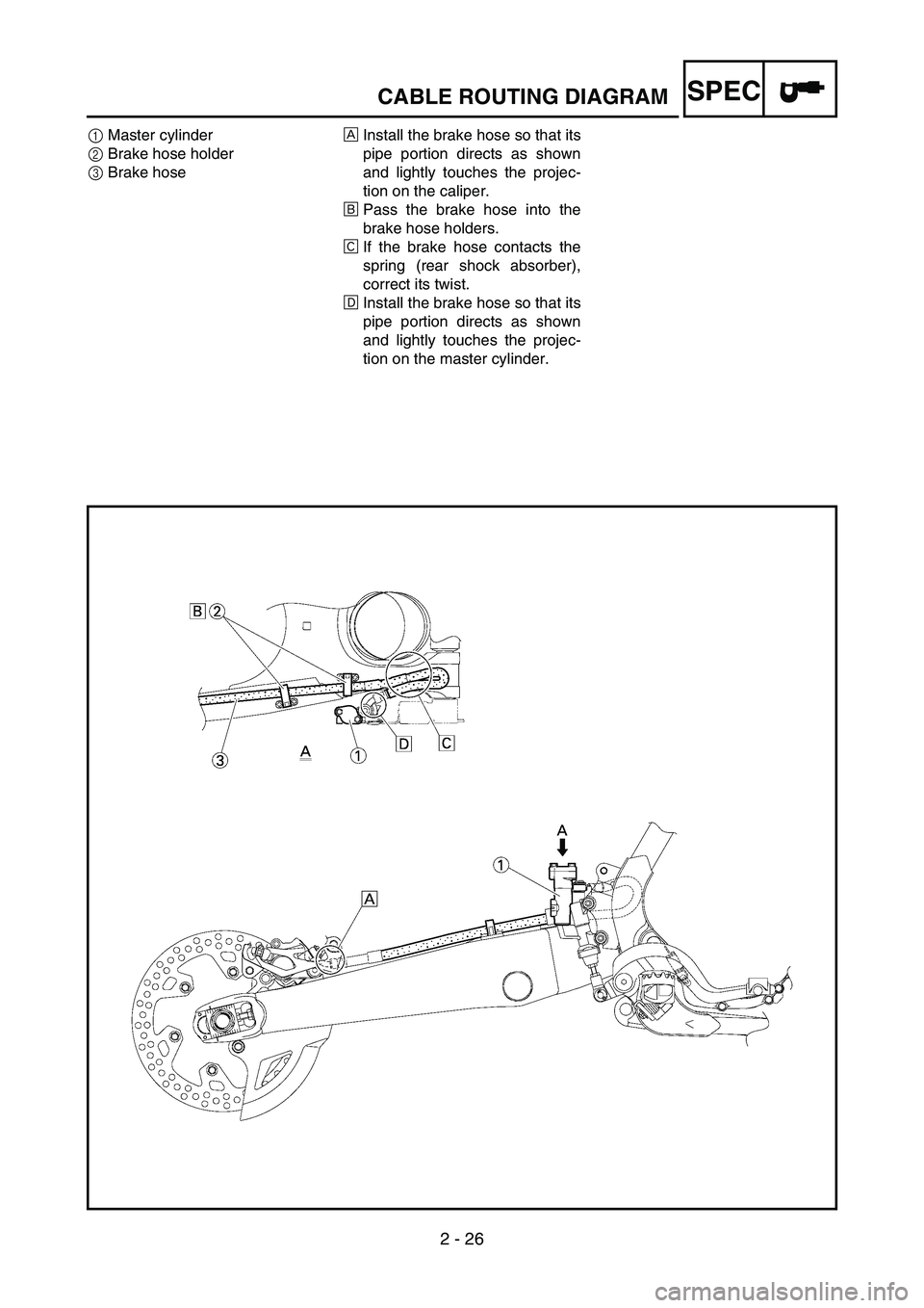
SPECCABLE ROUTING DIAGRAM
1Master cylinder
2Brake hose holder
3Brake hoseÈInstall the brake hose so that its
pipe portion directs as shown
and lightly touches the projec-
tion on the caliper.
ÉPass the brake hose into the
brake hose holders.
ÊIf the brake hose contacts the
spring (rear shock absorber),
correct its twist.
ËInstall the brake hose so that its
pipe portion directs as shown
and lightly touches the projec-
tion on the master cylinder.