YAMAHA WR 450F 2006 Owners Manual
Manufacturer: YAMAHA, Model Year: 2006, Model line: WR 450F, Model: YAMAHA WR 450F 2006Pages: 786, PDF Size: 22.49 MB
Page 351 of 786
ENG
4 - 17
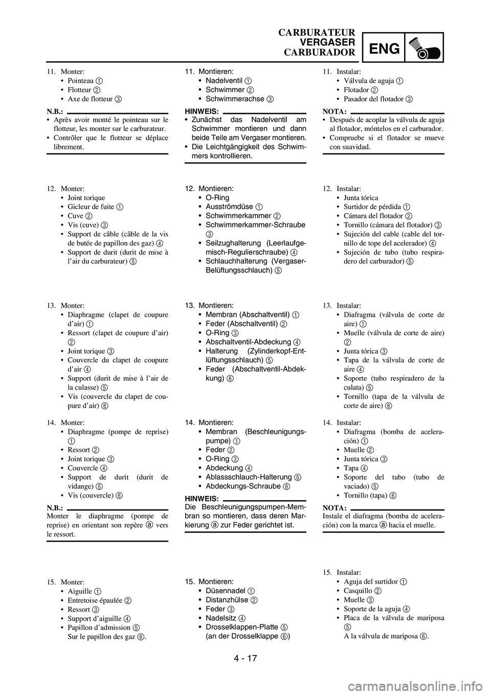
11. Montieren:
Nadelventil
1
Schwimmer
2
Schwimmerachse
3
HINWEIS:
Zunächst das Nadelventil am
Schwimmer montieren und dann
beide Teile am Vergaser montieren.
Die Leichtgängigkeit des Schwim-
mers kontrollieren.
12. Montieren:
O-Ring
Ausströmdüse
1
Schwimmerkammer
2
Schwimmerkammer-Schraube
3
Seilzughalterung (Leerlaufge-
misch-Regulierschraube)
4
Schlauchhalterung (Vergaser-
Belüftungsschlauch)
5
13. Montieren:
Membran (Abschaltventil)
1
Feder (Abschaltventil)
2
O-Ring
3
Abschaltventil-Abdeckung
4
Halterung (Zylinderkopf-Ent-
lüftungsschlauch)
5
Feder (Abschaltventil-Abdek-
kung)
6
14. Montieren:
Membran (Beschleunigungs-
pumpe)
1
Feder
2
O-Ring
3
Abdeckung
4
Ablassschlauch-Halterung
5
Abdeckungs-Schraube
6
HINWEIS:
Die Beschleunigungspumpen-Mem-
bran so montieren, dass deren Mar-
kierung
a zur Feder gerichtet ist.
15. Montieren:
Düsennadel
1
Distanzhülse
2
Feder
3
Nadelsitz
4
Drosselklappen-Platte
5
(an der Drosselklappe
6) 11. Monter:
Pointeau 1
Flotteur 2
Axe de flotteur 3
N.B.:
Après avoir monté le pointeau sur le
flotteur, les monter sur le carburateur.
Contrôler que le flotteur se déplace
librement.
12. Monter:
Joint torique
Gicleur de fuite 1
Cuve 2
Vis (cuve) 3
Support de câble (câble de la vis
de butée de papillon des gaz) 4
Support de durit (durit de mise à
l’air du carburateur) 5
13. Monter:
Diaphragme (clapet de coupure
d’air) 1
Ressort (clapet de coupure d’air)
2
Joint torique 3
Couvercle du clapet de coupure
d’air 4
Support (durit de mise à l’air de
la culasse) 5
Vis (couvercle du clapet de cou-
pure d’air) 6
14. Monter:
Diaphragme (pompe de reprise)
1
Ressort 2
Joint torique 3
Couvercle 4
Support de durit (durit de
vidange) 5
Vis (couvercle) 6
N.B.:
Monter le diaphragme (pompe de
reprise) en orientant son repère a vers
le ressort.
15. Monter:
Aiguille 1
Entretoise épaulée 2
Ressort 3
Support d’aiguille 4
Papillon d’admission 5
Sur le papillon des gaz 6.11. Instalar:
Válvula de aguja 1
Flotador 2
Pasador del flotador 3
NOTA:
Después de acoplar la válvula de aguja
al flotador, móntelos en el carburador.
Compruebe si el flotador se mueve
con suavidad.
12. Instalar:
Junta tórica
Surtidor de pérdida 1
Cámara del flotador 2
Tornillo (cámara del flotador) 3
Sujeción del cable (cable del tor-
nillo de tope del acelerador) 4
Sujeción de tubo (tubo respira-
dero del carburador) 5
13. Instalar:
Diafragma (válvula de corte de
aire) 1
Muelle (válvula de corte de aire)
2
Junta tórica 3
Tapa de la válvula de corte de
aire 4
Soporte (tubo respiradero de la
culata) 5
Tornillo (tapa de la válvula de
corte de aire) 6
14. Instalar:
Diafragma (bomba de acelera-
ción) 1
Muelle 2
Junta tórica 3
Tapa 4
Soporte del tubo (tubo de
vaciado) 5
Tornillo (tapa) 6
NOTA:
Instale el diafragma (bomba de acelera-
ción) con la marca a hacia el muelle.
15. Instalar:
Aguja del surtidor 1
Casquillo 2
Muelle 3
Soporte de la aguja 4
Placa de la válvula de mariposa
5
A la válvula de mariposa 6.
CARBURATEUR
VERGASER
CARBURADOR
Page 352 of 786
4 - 18
ENGCARBURETOR
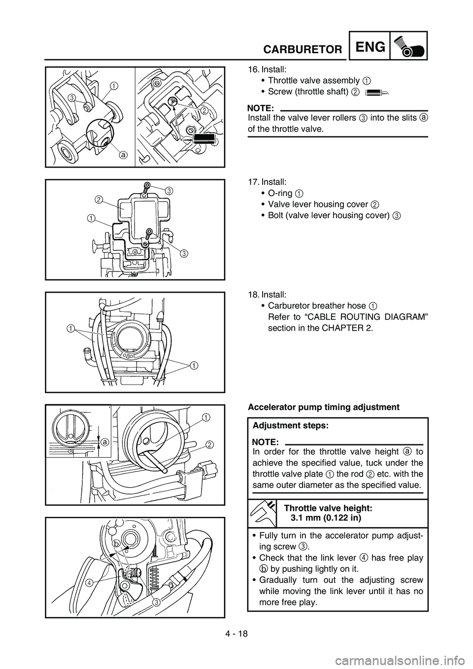
16. Install:
Throttle valve assembly 1
Screw (throttle shaft) 2
NOTE:
Install the valve lever rollers 3 into the slits a
of the throttle valve.
17. Install:
O-ring 1
Valve lever housing cover 2
Bolt (valve lever housing cover) 3
18. Install:
Carburetor breather hose 1
Refer to “CABLE ROUTING DIAGRAM”
section in the CHAPTER 2.
Accelerator pump timing adjustment
Adjustment steps:
NOTE:
In order for the throttle valve height a to
achieve the specified value, tuck under the
throttle valve plate 1 the rod 2 etc. with the
same outer diameter as the specified value.
Throttle valve height:
3.1 mm (0.122 in)
Fully turn in the accelerator pump adjust-
ing screw 3.
Check that the link lever 4 has free play
b by pushing lightly on it.
Gradually turn out the adjusting screw
while moving the link lever until it has no
more free play.
Page 353 of 786
ENG
4 - 18
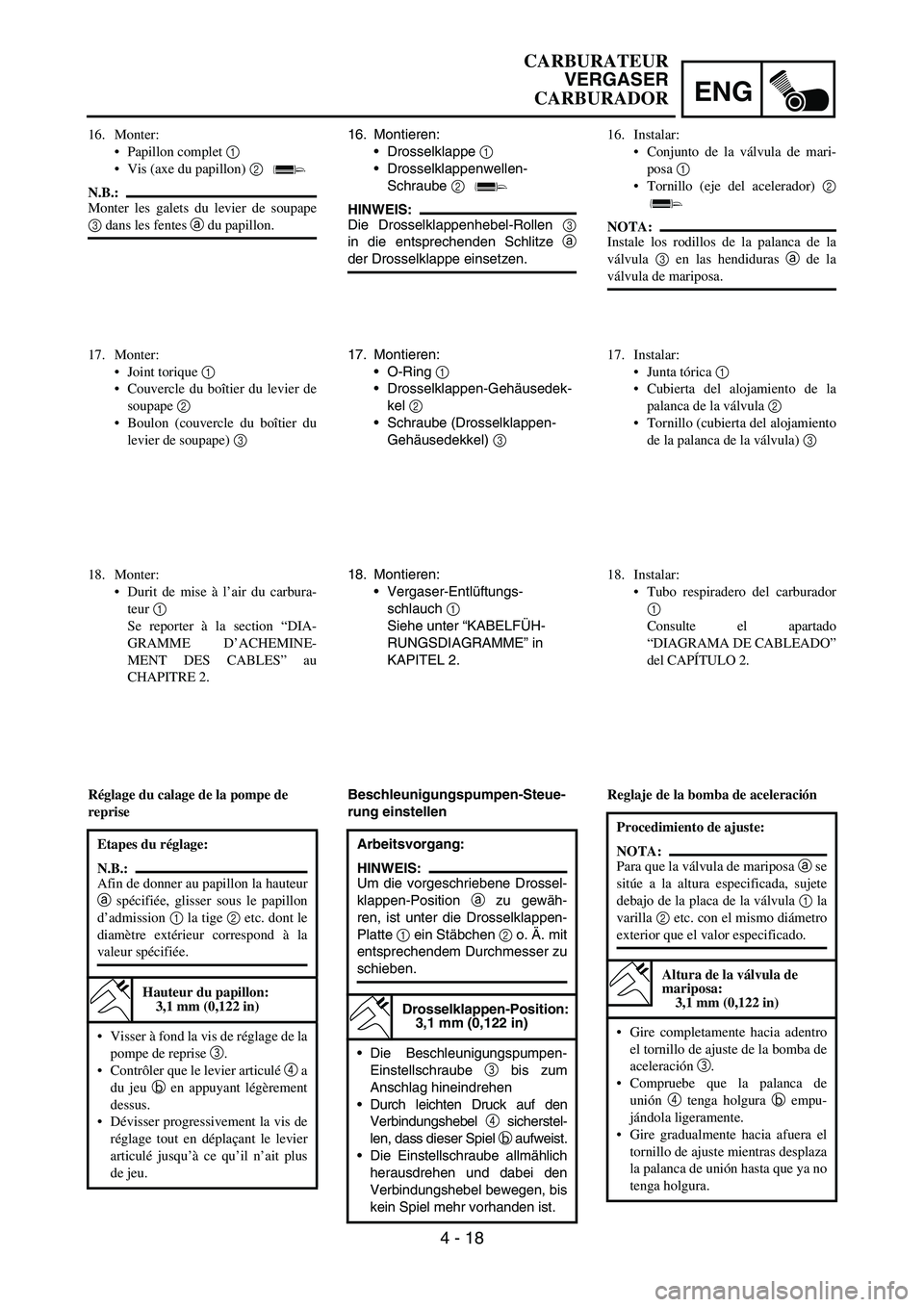
16. Montieren:
Drosselklappe
1
Drosselklappenwellen-
Schraube
2
HINWEIS:
Die Drosselklappenhebel-Rollen
3
in die entsprechenden Schlitze
a
der Drosselklappe einsetzen.
17. Montieren:
O-Ring
1
Drosselklappen-Gehäusedek-
kel
2
Schraube (Drosselklappen-
Gehäusedekkel)
3
18. Montieren:
Vergaser-Entlüftungs-
schlauch
1
Siehe unter “KABELFÜH-
RUNGSDIAGRAMME” in
KAPITEL 2.
Beschleunigungspumpen-Steue-
rung einstellen
Arbeitsvorgang:
HINWEIS:
Um die vorgeschriebene Drossel-
klappen-Position
a zu gewäh-
ren, ist unter die Drosselklappen-
Platte
1 ein Stäbchen
2 o. Ä. mit
entsprechendem Durchmesser zu
schieben.
Drosselklappen-Position:
3,1 mm (0,122 in)
Die Beschleunigungspumpen-
Einstellschraube
3 bis zum
Anschlag hineindrehen
Durch leichten Druck auf den
Verbindungshebel
4 sicherstel-
len, dass dieser Spiel
b aufweist.
Die Einstellschraube allmählich
herausdrehen und dabei den
Verbindungshebel bewegen, bis
kein Spiel mehr vorhanden ist.
16. Monter:
Papillon complet 1
Vis (axe du papillon) 2
N.B.:
Monter les galets du levier de soupape
3 dans les fentes a du papillon.
17. Monter:
Joint torique 1
Couvercle du boîtier du levier de
soupape 2
Boulon (couvercle du boîtier du
levier de soupape) 3
18. Monter:
Durit de mise à l’air du carbura-
teur 1
Se reporter à la section “DIA-
GRAMME D’ACHEMINE-
MENT DES CABLES” au
CHAPITRE 2.
Réglage du calage de la pompe de
reprise
Etapes du réglage:
N.B.:
Afin de donner au papillon la hauteur
a spécifiée, glisser sous le papillon
d’admission 1 la tige 2 etc. dont le
diamètre extérieur correspond à la
valeur spécifiée.
Hauteur du papillon:
3,1 mm (0,122 in)
Visser à fond la vis de réglage de la
pompe de reprise 3.
Contrôler que le levier articulé 4 a
du jeu b en appuyant légèrement
dessus.
Dévisser progressivement la vis de
réglage tout en déplaçant le levier
articulé jusqu’à ce qu’il n’ait plus
de jeu.
16. Instalar:
Conjunto de la válvula de mari-
posa 1
Tornillo (eje del acelerador) 2
NOTA:
Instale los rodillos de la palanca de la
válvula 3 en las hendiduras a de la
válvula de mariposa.
17. Instalar:
Junta tórica 1
Cubierta del alojamiento de la
palanca de la válvula 2
Tornillo (cubierta del alojamiento
de la palanca de la válvula) 3
18. Instalar:
Tubo respiradero del carburador
1
Consulte el apartado
“DIAGRAMA DE CABLEADO”
del CAPÍTULO 2.
Reglaje de la bomba de aceleración
Procedimiento de ajuste:
NOTA:
Para que la válvula de mariposa a se
sitúe a la altura especificada, sujete
debajo de la placa de la válvula 1 la
varilla 2 etc. con el mismo diámetro
exterior que el valor especificado.
Altura de la válvula de
mariposa:
3,1 mm (0,122 in)
Gire completamente hacia adentro
el tornillo de ajuste de la bomba de
aceleración 3.
Compruebe que la palanca de
unión 4 tenga holgura b empu-
jándola ligeramente.
Gire gradualmente hacia afuera el
tornillo de ajuste mientras desplaza
la palanca de unión hasta que ya no
tenga holgura.
CARBURATEUR
VERGASER
CARBURADOR
Page 354 of 786
4 - 19
ENGCARBURETOR
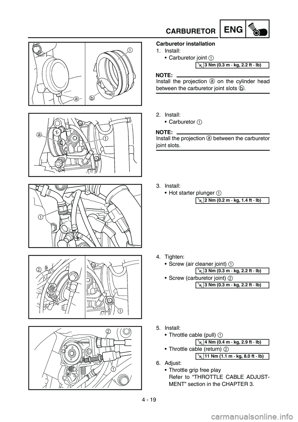
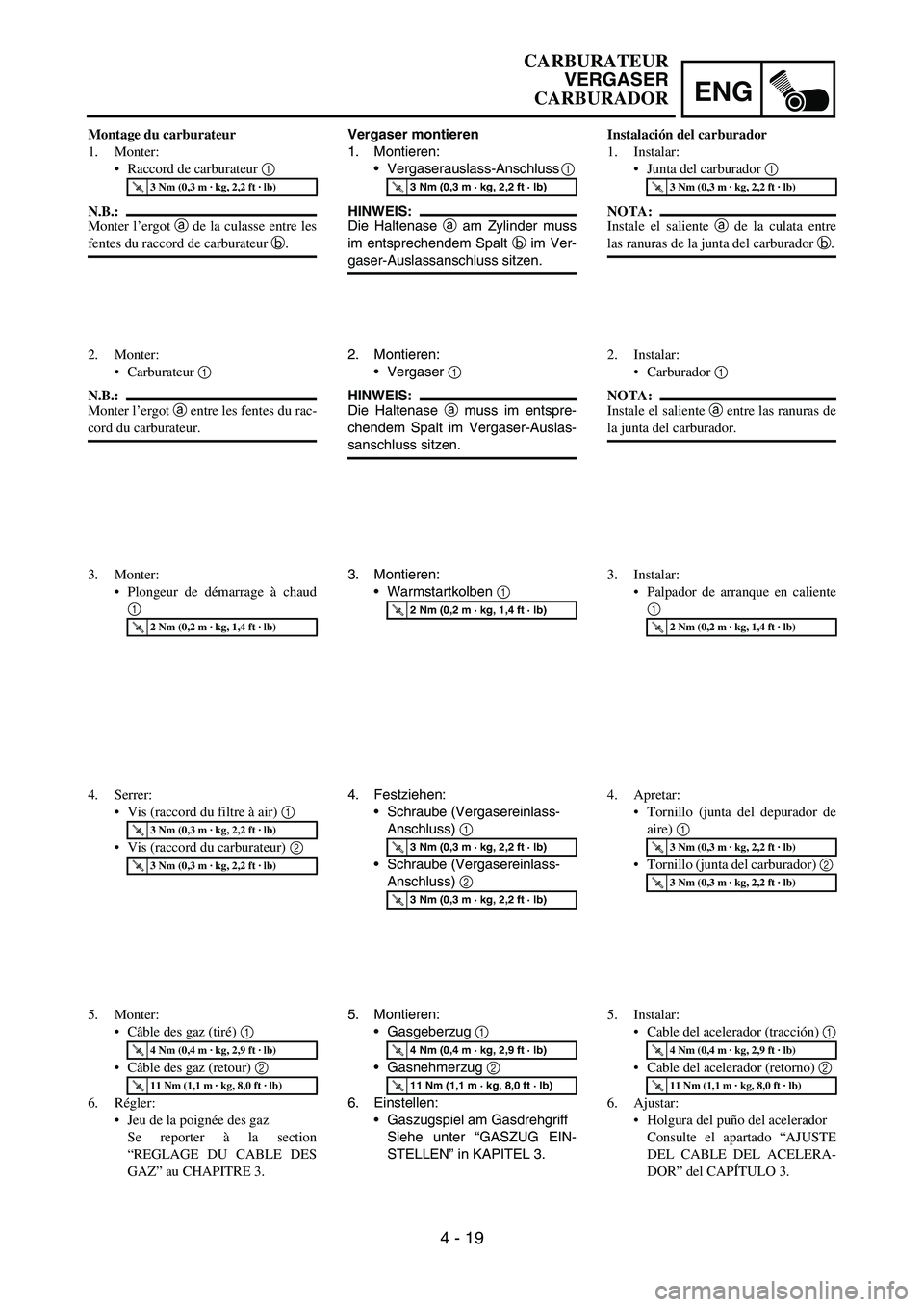
Carburetor installation
1. Install:
Carburetor joint 1
NOTE:
Install the projection a on the cylinder head
between the carburetor joint slots b.
T R..3 Nm (0.3 m · kg, 2.2 ft · lb)
2. Install:
Carburetor 1
NOTE:
Install the projection a between the carburetor
joint slots.
3. Install:
Hot starter plunger 1
1
T R..2 Nm (0.2 m · kg, 1.4 ft · lb)
4. Tighten:
Screw (air cleaner joint) 1
Screw (carburetor joint) 2
T R..3 Nm (0.3 m · kg, 2.2 ft · lb)
T R..3 Nm (0.3 m · kg, 2.2 ft · lb)
5. Install:
Throttle cable (pull) 1
Throttle cable (return) 2
6. Adjust:
Throttle grip free play
Refer to “THROTTLE CABLE ADJUST-
MENT” section in the CHAPTER 3.2
1
T R..4 Nm (0.4 m · kg, 2.9 ft · lb)
T R..11 Nm (1.1 m · kg, 8.0 ft · lb)
Page 355 of 786
ENG
4 - 19
Vergaser montieren
1. Montieren:
Vergaserauslass-Anschluss
1
HINWEIS:
Die Haltenase
a am Zylinder muss
im entsprechendem Spalt
b im Ver-
gaser-Auslassanschluss sitzen.
T R..3 Nm (0,3 m · kg, 2,2 ft · lb)
2. Montieren:
Vergaser
1
HINWEIS:
Die Haltenase
a muss im entspre-
chendem Spalt im Vergaser-Auslas-
sanschluss sitzen.
3. Montieren:
Warmstartkolben
1
T R..2 Nm (0,2 m · kg, 1,4 ft · lb)
4. Festziehen:
Schraube (Vergasereinlass-
Anschluss)
1
Schraube (Vergasereinlass-
Anschluss)
2
T R..3 Nm (0,3 m · kg, 2,2 ft · lb)
T R..3 Nm (0,3 m · kg, 2,2 ft · lb)
5. Montieren:
Gasgeberzug
1
Gasnehmerzug
2
6. Einstellen:
Gaszugspiel am Gasdrehgriff
Siehe unter “GASZUG EIN-
STELLEN” in KAPITEL 3.
T R..4 Nm (0,4 m · kg, 2,9 ft · lb)
T R..11 Nm (1,1 m · kg, 8,0 ft · lb)
Montage du carburateur
1. Monter:
Raccord de carburateur 1
N.B.:
Monter l’ergot a de la culasse entre les
fentes du raccord de carburateur b.
T R..3 Nm (0,3 m · kg, 2,2 ft · lb)
2. Monter:
Carburateur 1
N.B.:
Monter l’ergot a entre les fentes du rac-
cord du carburateur.
3. Monter:
Plongeur de démarrage à chaud
1
T R..2 Nm (0,2 m · kg, 1,4 ft · lb)
4. Serrer:
Vis (raccord du filtre à air) 1
Vis (raccord du carburateur) 2
T R..3 Nm (0,3 m · kg, 2,2 ft · lb)
T R..3 Nm (0,3 m · kg, 2,2 ft · lb)
5. Monter:
Câble des gaz (tiré) 1
Câble des gaz (retour) 2
6. Régler:
Jeu de la poignée des gaz
Se reporter à la section
“REGLAGE DU CABLE DES
GAZ” au CHAPITRE 3.
T R..4 Nm (0,4 m · kg, 2,9 ft · lb)
T R..11 Nm (1,1 m · kg, 8,0 ft · lb)
Instalación del carburador
1. Instalar:
Junta del carburador 1
NOTA:
Instale el saliente a de la culata entre
las ranuras de la junta del carburador b.
T R..3 Nm (0,3 m · kg, 2,2 ft · lb)
2. Instalar:
Carburador 1
NOTA:
Instale el saliente a entre las ranuras de
la junta del carburador.
3. Instalar:
Palpador de arranque en caliente
1
T R..2 Nm (0,2 m · kg, 1,4 ft · lb)
4. Apretar:
Tornillo (junta del depurador de
aire) 1
Tornillo (junta del carburador) 2
T R..3 Nm (0,3 m · kg, 2,2 ft · lb)
T R..3 Nm (0,3 m · kg, 2,2 ft · lb)
5. Instalar:
Cable del acelerador (tracción) 1
Cable del acelerador (retorno) 2
6. Ajustar:
Holgura del puño del acelerador
Consulte el apartado “AJUSTE
DEL CABLE DEL ACELERA-
DOR” del CAPÍTULO 3.
T R..4 Nm (0,4 m · kg, 2,9 ft · lb)
T R..11 Nm (1,1 m · kg, 8,0 ft · lb)
CARBURATEUR
VERGASER
CARBURADOR
Page 356 of 786
4 - 20
ENG
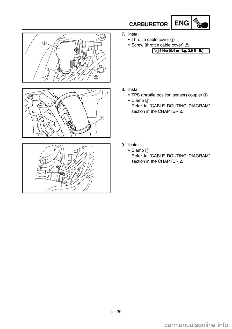
7. Install:
Throttle cable cover 1
Screw (throttle cable cover) 2
2 1
T R..4 Nm (0.4 m · kg, 2.9 ft · lb)
8. Install:
TPS (throttle position sensor) coupler 1
Clamp 2
Refer to “CABLE ROUTING DIAGRAM”
section in the CHAPTER 2.
9. Install:
Clamp 1
Refer to “CABLE ROUTING DIAGRAM”
section in the CHAPTER 2.
1
CARBURETOR
Page 357 of 786

ENG
4 - 20
7. Montieren:
Gaszug-Abdeckung
1
Schraube (Gaszug-Abdek-
kung)
2
T R..4 Nm (0,4 m · kg, 2,9 ft · lb)
8. Montieren:
Drosselklappensensor-Steck-
verbinder
1
Schlauchschelle
2
Siehe unter “KABELFÜH-
RUNGSDIAGRAMME” in
KAPITEL 2.
9. Montieren:
Schlauchschelle
1
Siehe unter “KABELFÜH-
RUNGSDIAGRAMME” in
KAPITEL 2. 7. Monter:
Couvercle du logement du câble
des gaz 1
Vis (couvercle du logement de
câble des gaz) 2
T R..4 Nm (0,4 m · kg, 2,9 ft · lb)
8. Monter:
Fiche rapide du TPS (capteur de
position de papillon des gaz) 1
Collier à pince 2
Se reporter à la section “DIA-
GRAMME D’ACHEMINE-
MENT DES CABLES” au
CHAPITRE 2.
9. Monter:
Collier à pince 1
Se reporter à la section “DIA-
GRAMME D’ACHEMINE-
MENT DES CABLES” au
CHAPITRE 2.7. Instalar:
Cubierta del cable del acelerador
1
Tornillo (cubierta del cable del
acelerador) 2
T R..4 Nm (0,4 m · kg, 2,9 ft · lb)
8. Instalar:
Acoplador del TPS (sensor de
posición del acelerador) 1
Brida 2
Consulte el apartado “DIAGRA-
MA DE CABLEADO” del CAPÍ-
TULO 2.
9. Instalar:
Brida 1
Consulte el apartado “DIAGRA-
MA DE CABLEADO” del CAPÍ-
TULO 2.
CARBURATEUR
VERGASER
CARBURADOR
Page 358 of 786
4 - 21
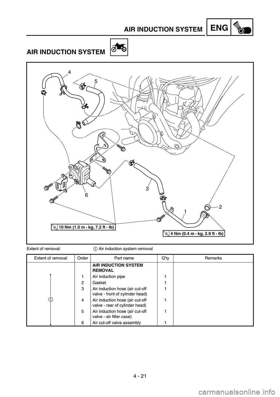
ENGAIR INDUCTION SYSTEM
AIR INDUCTION SYSTEM
2
1 3
65 4
T R..4 Nm (0.4 m •
kg, 2.9 ft • Ib)
T R..10 Nm (1.0 m •
kg, 7.2 ft • Ib)
Extent of removal:
1 Air induction system removal
Extent of removal Order Part name Q’ty Remarks
AIR INDUCTION SYSTEM
REMOVAL
1 Air induction pipe 1
2 Gasket 1
3 Air induction hose (air cut-off
valve - front of cylinder head)1
4 Air induction hose (air cut-off
valve - rear of cylinder head)1
5 Air induction hose (air cut-off
valve - air filter case)1
6 Air cut-off valve assembly 1
1
Page 359 of 786
ENG
4 - 21
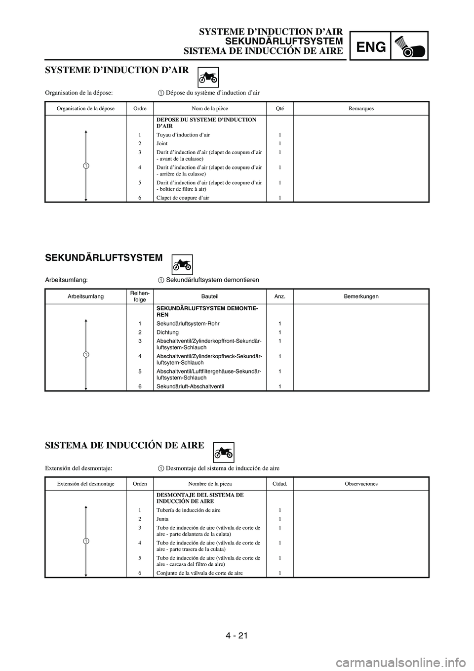
SEKUNDÄRLUFTSYSTEM
Arbeitsumfang:
1 Sekundärluftsystem demontieren
ArbeitsumfangReihen-
folgeBauteil Anz. Bemerkungen
SEKUNDÄRLUFTSYSTEM DEMONTIE-
REN
1 Sekundärluftsystem-Rohr 1
2 Dichtung 1
3 Abschaltventil/Zylinderkopffront-Sekundär-
luftsystem-Schlauch1
4 Abschaltventil/Zylinderkopfheck-Sekundär-
luftsytem-Schlauch1
5 Abschaltventil/Luftfiltergehäuse-Sekundär-
luftsystem-Schlauch1
6 Sekundärluft-Abschaltventil 1
1
SYSTEME D’INDUCTION D’AIR
Organisation de la dépose:1 Dépose du système d’induction d’air
Organisation de la dépose Ordre Nom de la pièce QtéRemarques
DEPOSE DU SYSTEME D’INDUCTION
D’AIR
1Tuyau d’induction d’air 1
2 Joint 1
3 Durit d’induction d’air (clapet de coupure d’air
- avant de la culasse)1
4 Durit d’induction d’air (clapet de coupure d’air
- arrière de la culasse)1
5 Durit d’induction d’air (clapet de coupure d’air
- boîtier de filtre à air)1
6 Clapet de coupure d’air 1
1
SISTEMA DE INDUCCIÓN DE AIRE
Extensión del desmontaje:1 Desmontaje del sistema de inducción de aire
Extensión del desmontaje Orden Nombre de la pieza Ctdad. Observaciones
DESMONTAJE DEL SISTEMA DE
INDUCCIÓN DE AIRE
1Tubería de inducción de aire 1
2Junta 1
3 Tubo de inducción de aire (válvula de corte de
aire - parte delantera de la culata)1
4 Tubo de inducción de aire (válvula de corte de
aire - parte trasera de la culata)1
5 Tubo de inducción de aire (válvula de corte de
aire - carcasa del filtro de aire)1
6 Conjunto de la válvula de corte de aire 1
1
SYSTEME D’INDUCTION D’AIR
SEKUNDÄRLUFTSYSTEM
SISTEMA DE INDUCCIÓN DE AIRE
Page 360 of 786
4 - 22
ENGAIR INDUCTION SYSTEM
INSPECTION
Air induction system
1. Inspect:
Air induction hose
Crack/damage → Replace.
Air induction pipe
Crack/damage → Replace.
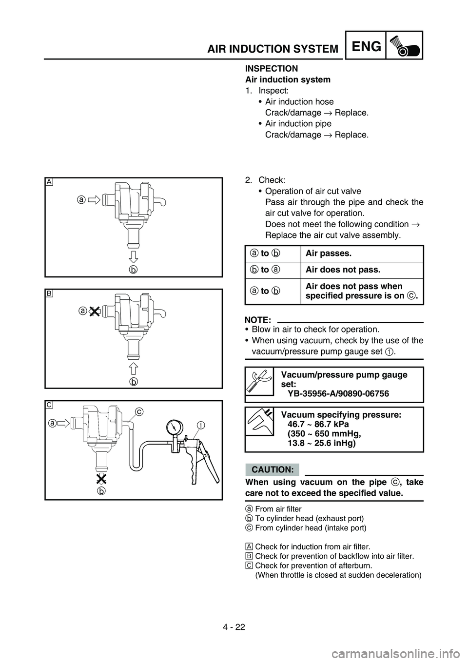
2. Check:
Operation of air cut valve
Pass air through the pipe and check the
air cut valve for operation.
Does not meet the following condition →
Replace the air cut valve assembly.
NOTE:
Blow in air to check for operation.
When using vacuum, check by the use of the
vacuum/pressure pump gauge set 1.
CAUTION:
When using vacuum on the pipe
c, take
care not to exceed the specified value.
aFrom air filter
bTo cylinder head (exhaust port)
cFrom cylinder head (intake port)
ÈCheck for induction from air filter.
ÉCheck for prevention of backflow into air filter.
ÊCheck for prevention of afterburn.
(When throttle is closed at sudden deceleration)
a to
b Air passes.
b to
a Air does not pass.
a to
b Air does not pass when
specified pressure is on
c.
Vacuum/pressure pump gauge
set:
YB-35956-A/90890-06756
Vacuum specifying pressure:
46.7 ~ 86.7 kPa
(350 ~ 650 mmHg,
13.8 ~ 25.6 inHg)
a
b
È
a
b
É
Ê