YAMAHA WR 450F 2016 Owners Manual
Manufacturer: YAMAHA, Model Year: 2016, Model line: WR 450F, Model: YAMAHA WR 450F 2016Pages: 426, PDF Size: 10.86 MB
Page 201 of 426
FRONT FORK
5-49
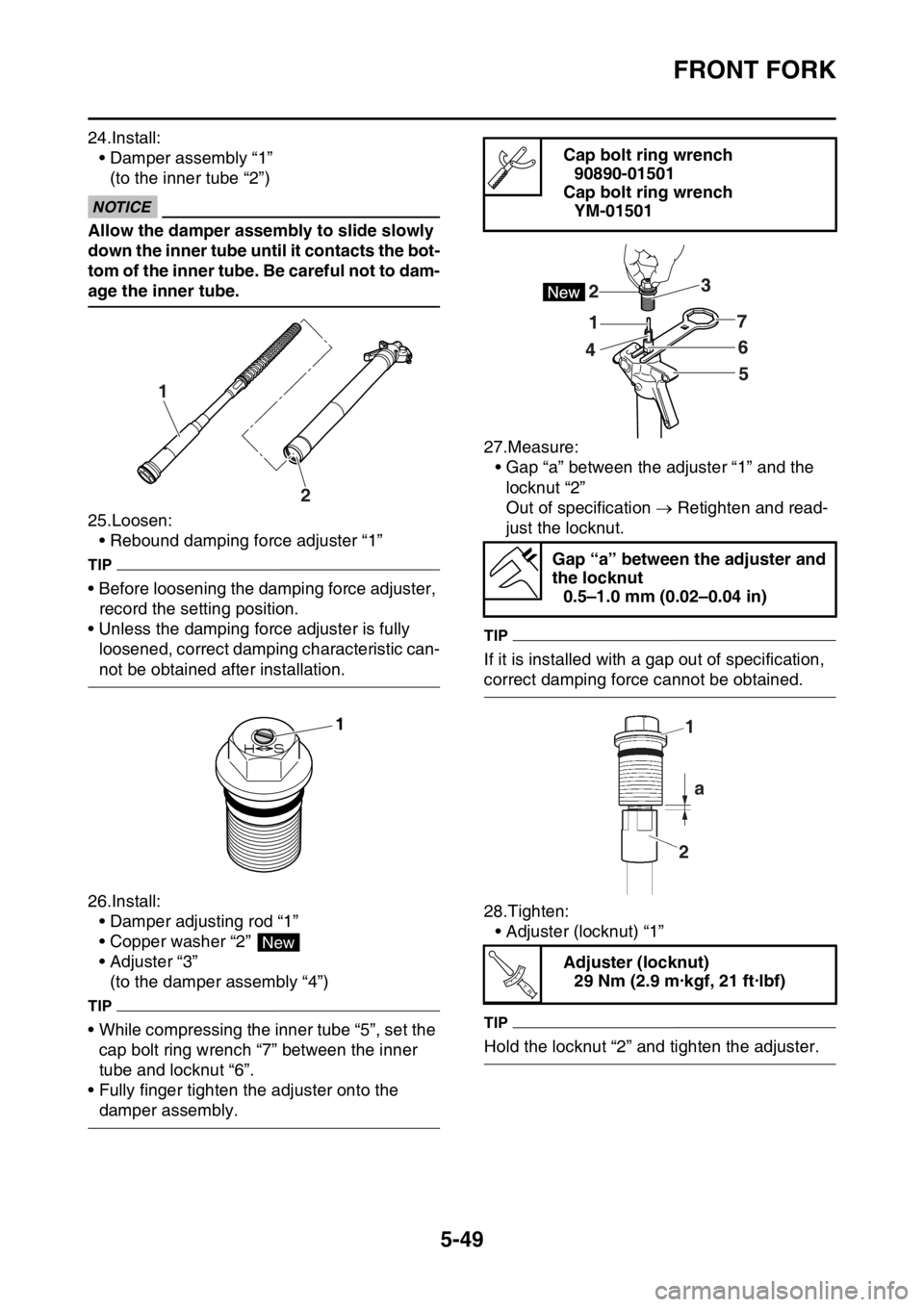
24.Install:• Damper assembly “1”(to the inner tube “2”)
ECA
NOTICE
Allow the damper assembly to slide slowly
down the inner tube until it contacts the bot-
tom of the inner tube. Be careful not to dam-
age the inner tube.
25.Loosen:
• Rebound damping force adjuster “1”
TIP
• Before loosening the damping force adjuster, record the setting position.
• Unless the damping force adjuster is fully loosened, correct damping characteristic can-
not be obtained after installation.
26.Install: • Damper adjusting rod “1”
• Copper washer “2”
• Adjuster “3”(to the damper assembly “4”)
TIP
• While compressing the inner tube “5”, set the cap bolt ring wrench “7” between the inner
tube and locknut “6”.
• Fully finger tighten the adjuster onto the
damper assembly. 27.Measure:
• Gap “a” between the adjuster “1” and the
locknut “2”
Out of specification Retighten and read-
just the locknut.
TIP
If it is installed with a gap out of specification,
correct damping force cannot be obtained.
28.Tighten:
• Adjuster (locknut) “1”
TIP
Hold the locknut “2” and tighten the adjuster.
1
2
1
New
Cap bolt ring wrench90890-01501
Cap bolt ring wrench YM-01501
Gap “a” between the adjuster and
the locknut 0.5–1.0 mm (0.02–0.04 in)
Adjuster (locknut) 29 Nm (2.9 m·kgf, 21 ft·lbf)
1
2 a
T R..
Page 202 of 426
FRONT FORK
5-50
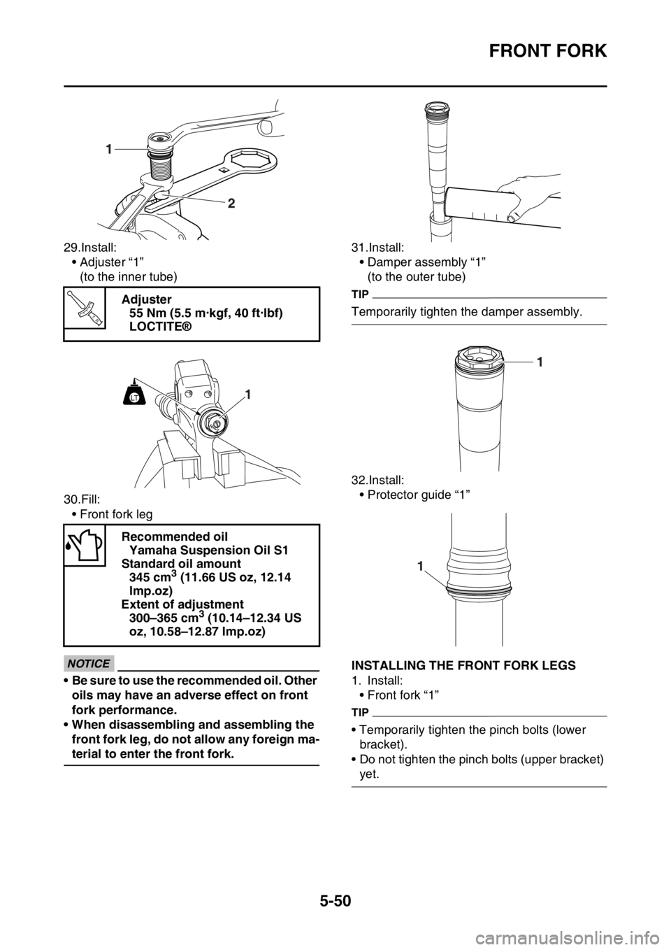
29.Install:• Adjuster “1”
(to the inner tube)
30.Fill: • Front fork leg
ECA
NOTICE
• Be sure to use the recommended oil. Other oils may have an adverse effect on front
fork performance.
• When disassembling and assembling the front fork leg, do not allow any foreign ma-
terial to enter the front fork. 31.Install:
• Damper assembly “1”
(to the outer tube)
TIP
Temporarily tighten the damper assembly.
32.Install:• Protector guide “1”
EAS2GC1202INSTALLING THE FRONT FORK LEGS
1. Install:• Front fork “1”
TIP
• Temporarily tighten the pinch bolts (lower bracket).
• Do not tighten the pinch bolts (upper bracket)
yet.
Adjuster
55 Nm (5.5 m·kgf, 40 ft·lbf)
LOCTITE®
Recommended oil Yamaha Suspension Oil S1
Standard oil amount 345 cm
3 (11.66 US oz, 12.14
lmp.oz)
Extent of adjustment 300–365 cm
3 (10.14–12.34 US
oz, 10.58–12.87 lmp.oz)
T R..
1LT
1
Page 203 of 426
FRONT FORK
5-51
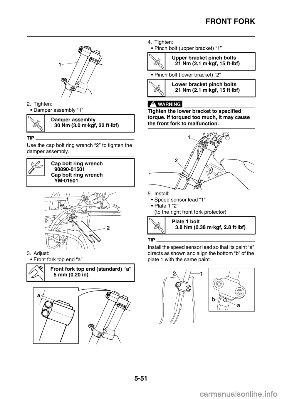
2. Tighten:• Damper assembly “1”
TIP
Use the cap bolt ring wrench “2” to tighten the
damper assembly.
3. Adjust:
• Front fork top end “a” 4. Tighten:
• Pinch bolt (upper bracket) “1”
• Pinch bolt (lower bracket) “2”
EWA
WARNING
Tighten the lower bracket to specified
torque. If torqued too much, it may cause
the front fork to malfunction.
5. Install:• Speed sensor lead “1”
• Plate 1 “2”(to the right front fork protector)
TIP
Install the speed sensor lead so that its paint “a”
directs as shown and align the bottom “b” of the
plate 1 with the same paint.
Damper assembly
30 Nm (3.0 m·kgf, 22 ft·lbf)
Cap bolt ring wrench 90890-01501
Cap bolt ring wrench YM-01501
Front fork top end (standard) “a” 5 mm (0.20 in)
T R..
2
1
a
Upper bracket pinch bolts21 Nm (2.1 m·kgf, 15 ft·lbf)
Lower bracket pinch bolts 21 Nm (2.1 m·kgf, 15 ft·lbf)
Plate 1 bolt 3.8 Nm (0.38 m·kgf, 2.8 ft·lbf)
T R..
T R..
2 1
T R..
1
2
a
b
Page 204 of 426
FRONT FORK
5-52
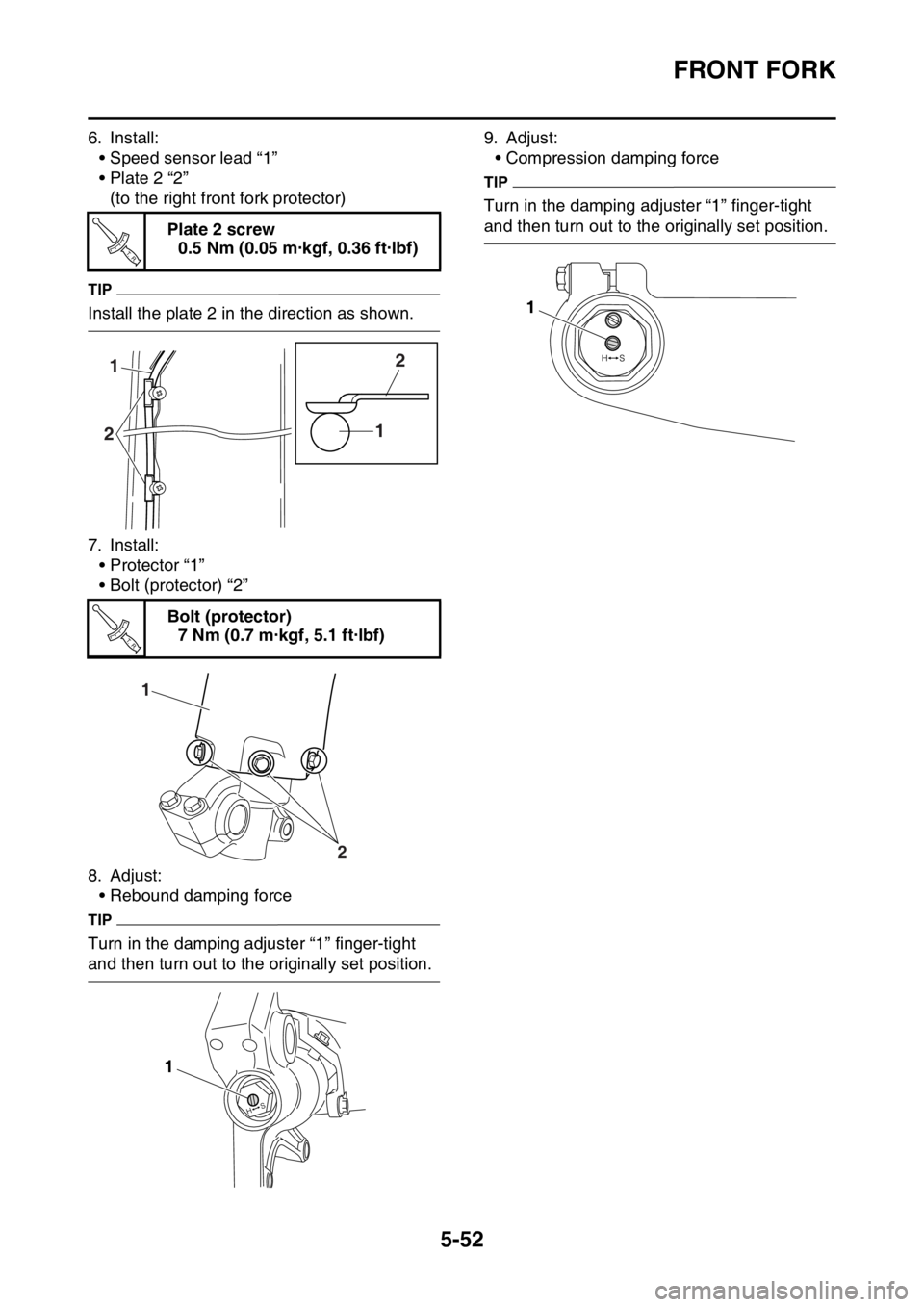
6. Install:• Speed sensor lead “1”
• Plate 2 “2”(to the right front fork protector)
TIP
Install the plate 2 in the direction as shown.
7. Install:• Protector “1”
• Bolt (protector) “2”
8. Adjust: • Rebound damping force
TIP
Turn in the damping adjuster “1” finger-tight
and then turn out to the originally set position. 9. Adjust:
• Compression damping force
TIP
Turn in the damping adjuster “1” finger-tight
and then turn out to the originally set position.
Plate 2 screw
0.5 Nm (0.05 m·kgf, 0.36 ft·lbf)
Bolt (protector) 7 Nm (0.7 m·kgf, 5.1 ft·lbf)
T R..
1
2 12
T R..
1
2
1
1
Page 205 of 426
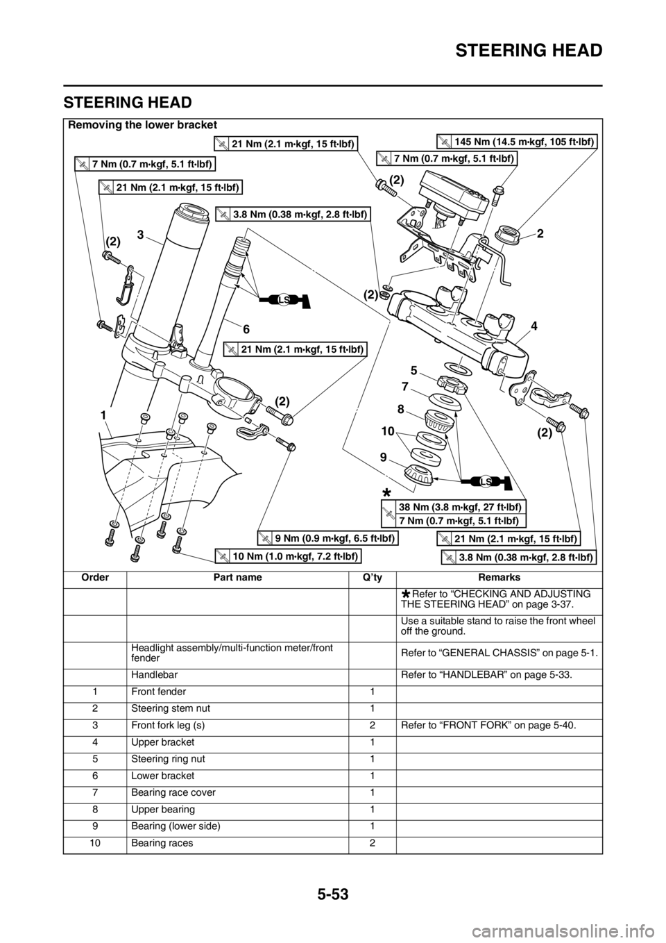
STEERING HEAD
5-53
EAS2GC1203
STEERING HEAD
Removing the lower bracket
OrderPart name Q’tyRemarks
Refer to “CHECKING AND ADJUSTING
THE STEERING HEAD” on page 3-37.
Use a suitable stand to raise the front wheel
off the ground.
Headlight assembly/multi -function meter/front
fender Refer to “GENERAL
CHASSIS” on page 5-1.
Handlebar Refer to “HANDLEBAR” on page 5-33.
1 Front fender 1
2 Steering stem nut 1
3 Front fork leg (s) 2 Refer to “FRONT FORK” on page 5-40.
4 Upper bracket 1
5 Steering ring nut 1
6 Lower bracket 1
7 Bearing race cover 1
8 Upper bearing 1
9 Bearing (lower side) 1
10 Bearing races 2
2
4
5
7
3
(2) (2)
(2)
(2)
(2)
1
6
8
9
10
LS
LS
T
.R.21 Nm (2.1 mlbf)
kgf, 15 ft
T
.R.21 Nm (2.1 mlbf)
kgf, 15 ft
T
.R.21 Nm (2.1 mlbf)
kgf, 15 ft
T
.R.21 Nm (2.1 mlbf)
kgf, 15 ft
T
.R.3.8 Nm (0.38 mlbf)
kgf, 2.8 ft
T
.R.3.8 Nm (0.38 mlbf)
kgf, 2.8 ft
T
.R.9 Nm (0.9 mlbf)
kgf, 6.5 ft
T
.R.7 Nm (0.7 mlbf)
kgf, 5.1 ftT
.R.7 Nm (0.7 mlbf)
kgf, 5.1 ft
T
.R.10 Nm (1.0 mlbf)
kgf, 7.2 ft
T
.R.145 Nm (14.5 mlbf)
kgf, 105 ft
T
.R.38 Nm (3.8 mlbf)
kgf, 27 ft
7 Nm (0.7 m
lbf)
kgf, 5.1 ft
*
*
Page 206 of 426
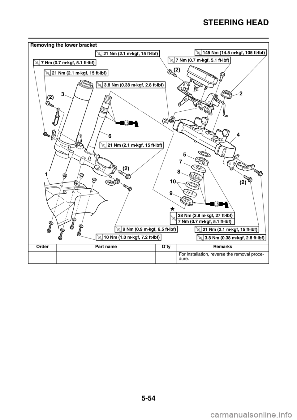
STEERING HEAD
5-54
For installation, reverse the removal proce-
dure.
Removing the lower bracket
OrderPart name Q’tyRemarks
2
4
5
7
3
(2) (2)
(2)
(2)
(2)
1
6
8
9
10
LS
LS
T
.R.21 Nm (2.1 mlbf)
kgf, 15 ft
T
.R.21 Nm (2.1 mlbf)
kgf, 15 ft
T
.R.21 Nm (2.1 mlbf)
kgf, 15 ft
T
.R.21 Nm (2.1 mlbf)
kgf, 15 ft
T
.R.3.8 Nm (0.38 mlbf)
kgf, 2.8 ft
T
.R.3.8 Nm (0.38 mlbf)
kgf, 2.8 ft
T
.R.9 Nm (0.9 mlbf)
kgf, 6.5 ft
T
.R.7 Nm (0.7 mlbf)
kgf, 5.1 ftT
.R.7 Nm (0.7 mlbf)
kgf, 5.1 ft
T
.R.10 Nm (1.0 mlbf)
kgf, 7.2 ft
T
.R.145 Nm (14.5 mlbf)
kgf, 105 ft
T
.R.38 Nm (3.8 mlbf)
kgf, 27 ft
7 Nm (0.7 m
lbf)
kgf, 5.1 ft
*
Page 207 of 426
STEERING HEAD
5-55
EAS2GC1204REMOVING THE LOWER BRACKET
1. Use a suitable stand to raise the front wheel off the ground.
EWA
WARNING
Securely support the vehicle so that there is
no danger of it falling over.
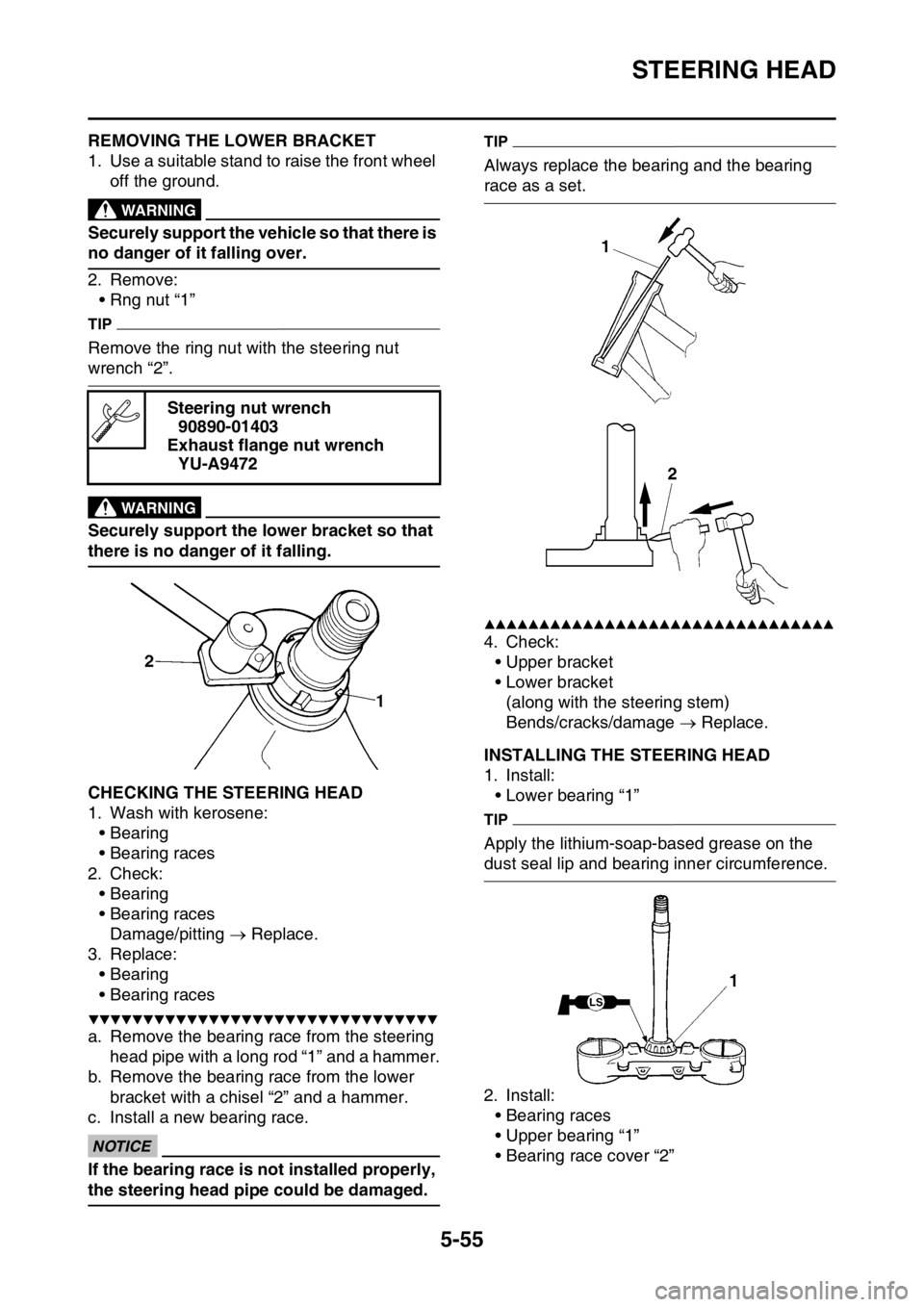
2. Remove:• Rng nut “1”
TIP
Remove the ring nut with the steering nut
wrench “2”.
EWA
WARNING
Securely support the lower bracket so that
there is no danger of it falling.
EAS2GC1205CHECKING THE STEERING HEAD
1. Wash with kerosene:• Bearing
• Bearing races
2. Check: • Bearing
• Bearing races
Damage/pitting Replace.
3. Replace:
• Bearing
• Bearing races
▼▼▼▼▼▼▼▼▼▼▼▼▼▼▼▼▼▼▼▼▼▼▼▼▼▼▼▼▼▼▼▼
a. Remove the bearing race from the steering head pipe with a long rod “1” and a hammer.
b. Remove the bearing race from the lower bracket with a chisel “2” and a hammer.
c. Install a new bearing race.
ECA
NOTICE
If the bearing race is not installed properly,
the steering head pipe could be damaged.
TIP
Always replace the bearing and the bearing
race as a set.
▲▲▲▲▲▲▲▲▲▲▲▲▲▲▲▲▲▲▲▲▲▲▲▲▲▲▲▲▲▲▲▲
4. Check: • Upper bracket
• Lower bracket
(along with the steering stem)
Bends/cracks/damage Replace.
EAS2GC1206INSTALLING THE STEERING HEAD
1. Install:
• Lower bearing “1”
TIP
Apply the lithium-soap-based grease on the
dust seal lip and bearing inner circumference.
2. Install:• Bearing races
• Upper bearing “1”
• Bearing race cover “2”
Steering nut wrench
90890-01403
Exhaust flange nut wrench YU-A9472
Page 208 of 426
STEERING HEAD
5-56
TIP
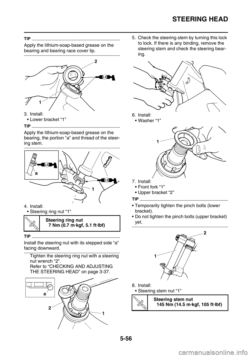
Apply the lithium-soap-based grease on the
bearing and bearing race cover lip.
3. Install:• Lower bracket “1”
TIP
Apply the lithium-soap-based grease on the
bearing, the portion “a” and thread of the steer-
ing stem.
4. Install:• Steering ring nut “1”
TIP
Install the steering nut with its stepped side “a”
facing downward.
Tighten the steering ring nut with a steering
nut wrench “2”.
Refer to “CHECKING AND ADJUSTING
THE STEERING HEAD” on page 3-37. 5. Check the steering stem by turning this lock
to lock. If there is any binding, remove the
steering stem and check the steering bear-
ing.
6. Install: • Washer “1”
7. Install: • Front fork “1”
• Upper bracket “2”
TIP
• Temporarily tighten the pinch bolts (lower bracket).
• Do not tighten the pinch bolts (upper bracket)
yet.
8. Install: • Steering stem nut “1”
Steering ring nut
7 Nm (0.7 m·kgf, 5.1 ft·lbf)
LS
1
a
LSLS
T R..
Steering stem nut
145 Nm (14.5 m·kgf, 105 ft·lbf)
T R..
Page 209 of 426
STEERING HEAD
5-57
TIP
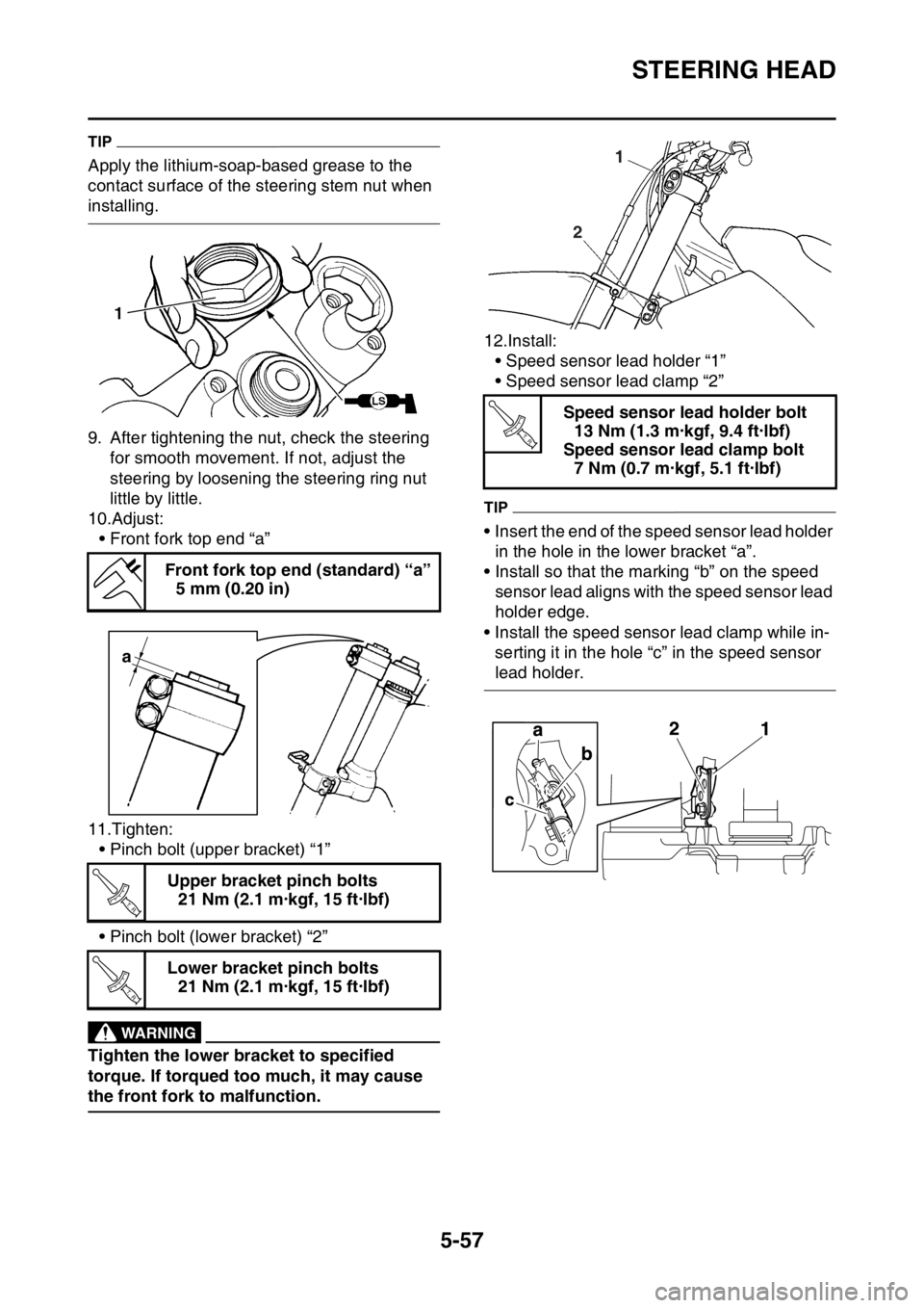
Apply the lithium-soap-based grease to the
contact surface of the steering stem nut when
installing.
9. After tightening the nut, check the steering for smooth movement. If not, adjust the
steering by loosening the steering ring nut
little by little.
10.Adjust:
• Front fork top end “a”
11.Tighten: • Pinch bolt (upper bracket) “1”
• Pinch bolt (lower bracket) “2”
EWA
WARNING
Tighten the lower bracket to specified
torque. If torqued too much, it may cause
the front fork to malfunction. 12.Install:
• Speed sensor lead holder “1”
• Speed sensor lead clamp “2”
TIP
• Insert the end of the speed sensor lead holder
in the hole in the lower bracket “a”.
• Install so that the marking “b” on the speed sensor lead aligns with the speed sensor lead
holder edge.
• Install the speed sens or lead clamp while in-
serting it in the hole “c” in the speed sensor
lead holder.
Front fork top end (standard) “a”
5 mm (0.20 in)
Upper bracket pinch bolts 21 Nm (2.1 m·kgf, 15 ft·lbf)
Lower bracket pinch bolts 21 Nm (2.1 m·kgf, 15 ft·lbf)
a
T R..
T R..
Speed sensor lead holder bolt13 Nm (1.3 m·kgf, 9.4 ft·lbf)
Speed sensor lead clamp bolt 7 Nm (0.7 m·kgf, 5.1 ft·lbf)
2 1
T R..
Page 210 of 426
REAR SHOCK ABSORBER ASSEMBLY
5-58
EAS2GC1207
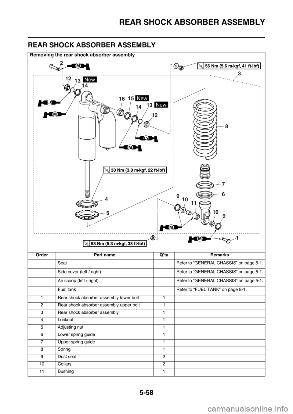
REAR SHOCK ABSORBER ASSEMBLY
Removing the rear shock absorber assembly
OrderPart name Q’tyRemarks
Seat Refer to “GENERAL CHASSIS” on page 5-1.
Side cover (left / right) Refer to “GENERAL CHASSIS” on page 5-1.
Air scoop (left / right) Refer to “GENERAL CHASSIS” on page 5-1.
Fuel tank Refer to “FUEL TANK” on page 8-1.
1 Rear shock absorber assembly lower bolt 1
2 Rear shock absorber assembly upper bolt 1
3 Rear shock absorber assembly 1
4 Locknut 1
5 Adjusting nut 1
6 Lower spring guide 1
7 Upper spring guide 1
8Spring 1
9 Dust seal 2
10 Collars 2
11 Bushing 1
2
12
1615
14 13
12
14
4
5
7
6
8 3
9
9
10
10
11
1
New
New
13New
LS
LS
M
M
M
M
M