YAMAHA XMAX 125 2022 Owner's Guide
Manufacturer: YAMAHA, Model Year: 2022, Model line: XMAX 125, Model: YAMAHA XMAX 125 2022Pages: 118, PDF Size: 13.61 MB
Page 31 of 118
Stop and Start System
4-1
4
EAU76825
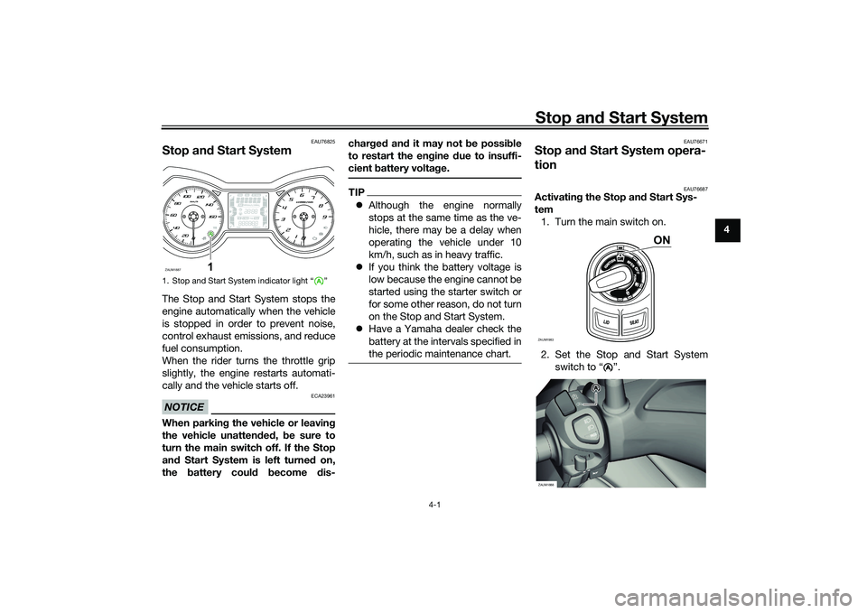
Stop an d Start SystemThe Stop and Start System stops the
engine automatically when the vehicle
is stopped in order to prevent noise,
control exhaust emissions, and reduce
fuel consumption.
When the rider turns the throttle grip
slightly, the engine restarts automati-
cally and the vehicle starts off.NOTICE
ECA23961
When parkin g the vehicle or leavin g
the vehicle unatten ded , be sure to
turn the main switch off. If the Stop
an d Start System is left turne d on,
the battery could become dis- char
ged an d it may not be possi ble
to restart the en gine due to insuffi-
cient battery volta ge.
TIP Although the engine normally
stops at the same time as the ve-
hicle, there may be a delay when
operating the vehicle under 10
km/h, such as in heavy traffic.
If you think the battery voltage is
low because the engine cannot be
started using the starter switch or
for some other reason, do not turn
on the Stop and Start System.
Have a Yamaha dealer check the
battery at the intervals specified in
the periodic maintenance chart.
EAU76671
Stop an d Start System opera-
tion
EAU76687
Activatin g the Stop an d Start Sys-
tem 1. Turn the main switch on.
2. Set the Stop and Start System switch to “ ”.
1. Stop and Start System indicator light “ ”ZAUM1887
1
ZAUM1983
ON
A
AA
ZAUM1888
UB9YE1E0.book Page 1 Tuesday, October 12, 2021 2:29 PM
Page 32 of 118

Stop and Start System
4-2
4 3. The Stop and Start System acti-
vates and the indicator light
comes on when the following con-
ditions are met: The Stop and Start System
switch is set to “ ”.
After the engine was warmed
up, the engine was left idling
for a certain period.
The vehicle has traveled at a
speed of 10 km/h or higher.
4. To turn off the Stop and Start Sys- tem, set the Stop and Start Sys-
tem switch to “ ”.
TIPTo preserve battery power, the
Stop and Start System may not
activate.
If the Stop and Start System does
not activate, have a Yamaha deal-
er check the battery.
EAU76832
Stop the en gine
The engine will stop automatically
when the following conditions are met: The Stop and Start System switch
is set to “ ”.
The “ ” indicator light on the
multi-function meter is on.
The vehicle is stopped with the
throttle grip fully returned. At this time, the “ ” indicator light
starts flashing to indicate that the en-
gine is currently stopped by the Stop
and Start System.
EAU76704
Restart the en
gine
If the throttle grip is turned while the
Stop and Start System indicator light is
flashing, the engine will automatically
restart and the “ ” indicator light will
stop flashing.
1. Stop and Start System indicator light “ ”
A
ZAUM1889
1
A
AAAA
A
ZAUM1890
AA
A
1. On
2. Flashing
A
1
2
A
UB9YE1E0.book Page 2 Tuesday, October 12, 2021 2:29 PM
Page 33 of 118
Stop and Start System
4-3
4
WARNING
EWA18731
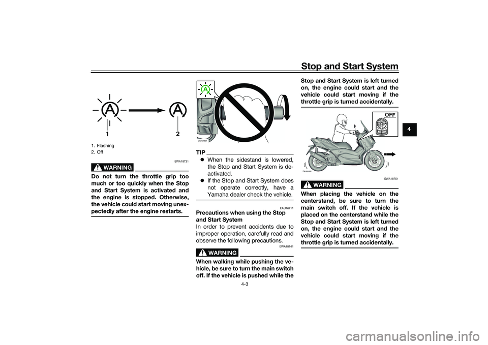
Do not turn the throttle g rip too
much or too quickly when the Stop
an d Start System is activate d an d
the en gine is stoppe d. Otherwise,
the vehicle coul d start movin g unex-
pected ly after the en gine restarts.
TIP When the sidestand is lowered,
the Stop and Start System is de-
activated.
If the Stop and Start System does
not operate correctly, have a
Yamaha dealer check the vehicle.
EAU76711
Precautions when usin g the Stop
an d Start System
In order to prevent accidents due to
improper operation, carefully read and
observe the following precautions.
WARNING
EWA18741
When walkin g while pushin g the ve-
hicle, be sure to turn the main switch
off. If the vehicle is pushe d while the Stop an
d Start System is left turned
on, the en gine coul d start an d the
vehicle coul d start movin g if the
throttle grip is turne d acci dentally.
WARNING
EWA18751
When placin g the vehicle on the
centerstan d, be sure to turn the
main switch off. If the vehicle is
placed on the centerstand while the
Stop an d Start System is left turned
on, the en gine coul d start an d the
vehicle coul d start movin g if the
throttle grip is turne d acci dentally.
1. Flashing
2. Off
1
2
ZAUM1891
ZAUM1892UM1892
OFF
UB9YE1E0.book Page 3 Tuesday, October 12, 2021 2:29 PM
Page 34 of 118
Stop and Start System
4-4
4
WARNING
EWA18771
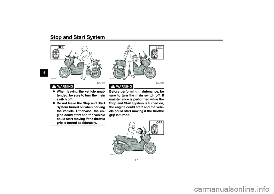
When leavin g the vehicle unat-
ten ded , b e sure to turn the main
switch off.
Do not leave the Stop an d Start
System turne d on when parkin g
the vehicle. Otherwise, the en-
g ine coul d start an d the vehicle
coul d start movin g if the throttle
g rip is turne d acci dentally.
WARNING
EWA18781
Before performin g maintenance, b e
sure to turn the main switch off. If
maintenance is performed while the
Stop an d Start System is turne d on,
the en gine coul d start an d the vehi-
cle coul d start movin g if the throttle
g rip is turne d.
ZAUM1893
OFF
ZAUM1894UM1894
OFF
ZAUM1895UM1895
OFF
UB9YE1E0.book Page 4 Tuesday, October 12, 2021 2:29 PM
Page 35 of 118
Instrument and control functions
5-1
5
EAU4939R
In dicator lig hts and warning
lig hts
EAU88680
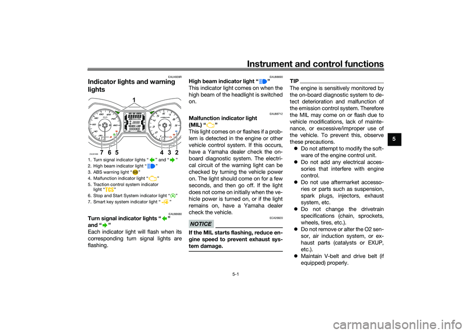
Turn si gnal in dicator li ghts “ ”
an d“”
Each indicator light will flash when its
corresponding turn signal lights are
flashing.
EAU88690
Hi gh beam in dicator li ght “ ”
This indicator light comes on when the
high beam of the headlight is switched
on.
EAU88712
Malfunction in dicator li ght
(MIL) “ ”
This light comes on or flashes if a prob-
lem is detected in the engine or other
vehicle control system. If this occurs,
have a Yamaha dealer check the on-
board diagnostic system. The electri-
cal circuit of the warning light can be
checked by turning the vehicle power
on. The light should come on for a few
seconds, and then go off. If the light
does not come on initially when the ve-
hicle power is turned on, or if the light
remains on, have a Yamaha dealer
check the vehicle.NOTICE
ECA26820
If the MIL starts flashin g, re duce en-
g ine spee d to prevent exhaust sys-
tem damag e.
TIPThe engine is sensitively monitored by
the on-board diagnostic system to de-
tect deterioration and malfunction of
the emission control system. Therefore
the MIL may come on or flash due to
vehicle modifications, lack of mainte-
nance, or excessive/improper use of
the vehicle. To prevent this, observe
these precautions.
Do not attempt to modify the soft-
ware of the engine control unit.
Do not add any electrical acces-
sories that interfere with engine
control.
Do not use aftermarket accesso-
ries or parts such as suspension,
spark plugs, injectors, exhaust
system, etc.
Do not change the drivetrain
specifications (chain, sprockets,
wheels, tires, etc.).
Do not remove or alter the O2 sen-
sor, air induction system, or ex-
haust parts (catalysts or EXUP,
etc.).
Maintain V-belt and drive belt (if
equipped) properly.
1. Turn signal indicator lights “ ” and “ ”
2. High beam indicator light “ ”
3. ABS warning light “ ”
4. Malfunction indicator light “ ”
5. Traction control system indicator
light “ ”
6. Stop and Start System indicator light “ ”
7. Smart key system indicator light “ ”ZAUM1896
1
234
567
UB9YE1E0.book Page 1 Tuesday, October 12, 2021 2:29 PM
Page 36 of 118

Instrument and control functions
5-2
5
Maintain correct tire pressure.
Do not operate the vehicle in an
extreme manner. For example, re-
peated or excessive opening and
closing of the throttle, racing,
burnouts, wheelies, etc.
EAU88890
ABS warnin g li ght “ ”
This warning light comes on when the
vehicle is first turned on, and goes off
after starting riding. If the warning light
comes on while riding, the anti-lock
brake system may not work correctly.
WARNING
EWA16043
If the ABS warnin g lig ht does not
turn off after reachin g 10 km/h (6
mi/h), or if the warnin g li ght comes
on while ri din g:
Use extra caution to avoi d pos-
si ble wheel lock d uring emer-
g ency brakin g.
Have a Yamaha dealer check
the vehicle as soon as possi ble.
TIPThe ABS warning light may come on
while revving the engine with the vehi-
cle on its centerstand, but this does
not indicate a malfunction.
EAU88930
Traction control system in dicator
li g ht “ ”
This indicator light will flash when trac-
tion control has engaged.
If the traction control system is turned
off, this indicator light will come on.
(See page 5-15.)TIPWhen the vehicle is turned on, the light
should come on for a few seconds and
then go off. If the light does not come
on, or if the light remains on, have a
Yamaha dealer check vehicle.
EAUN2772
Smart key system in dicator
li g ht “ ”
This indicator light communicates the
status of the smart key system. When
the smart key system is operating nor-
mally, this indicator light will be off. If there is an error in the smart key sys-
tem, the indicator light will flash. The
indicator light will also flash when com-
munication between the vehicle and
smart key takes place and when cer-
tain smart key system operations are
carried out.
EAUN2830
Stop an
d Start System in dicator
li g ht “ ”
This indicator light comes on when the
Stop and Start System activates. The
indicator light will flash when the en-
gine is automatically stopped by the
Stop and Start System.TIPEven if the Stop and Start Switch is set
to “ ”, this indicator light may not
come on. (See page 4-1.)
A
UB9YE1E0.book Page 2 Tuesday, October 12, 2021 2:29 PM
Page 37 of 118

Instrument and control functions
5-3
5
EAU63544
Spee dometerFor the UK
The speedometer shows the vehicle’s
traveling speed. When the vehicle power is turned on,
the speedometer needle will sweep
once across the speed range and then
return to zero in order to test the elec-
trical circuit.
EAU63551
TachometerThe electric tachometer allows the rid-
er to monitor the engine speed and
keep it within the ideal power range.
When the vehicle power is turned on,
the tachometer needle will sweep once
across the r/min range and then return
to zero r/min in order to test the electri-
cal circuit.NOTICE
ECA10032
Do not operate the en
gine in the ta-
chometer red zone.
Re d zone: 10000 r/min an d a bove
1. Speedometer
1. SpeedometerZAUM18971ZAUM18981
1. Tachometer
2. Tachometer red zoneZAUM1534
1
2
UB9YE1E0.book Page 3 Tuesday, October 12, 2021 2:29 PM
Page 38 of 118
Instrument and control functions
5-4
5
EAU78486
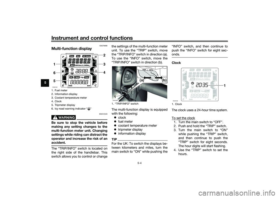
Multi-function d isplay
WARNING
EWA12423
Be sure to stop the vehicle b efore
makin g any settin g chan ges to the
multi-function meter unit. Chan gin g
settin gs while ri din g can d istract the
operator an d increase the risk of an
acci dent.The “TRIP/INFO” switch is located on
the right side of the handlebar. This
switch allows you to control or change the settings of the multi-function meter
unit. To use the “TRIP” switch, move
the “TRIP/INFO” switch in direction (a).
To use the “INFO” switch, move the
“TRIP/INFO” switch in direction (b).
The multi-function display is equipped
with the following:
clock
fuel meter
coolant temperature meter
tripmeter display
information display
TIPFor the UK: To switch the displays be-
tween kilometers and miles, turn the
main switch to “ON” while pushing the “INFO” switch, and then continue to
push the “INFO” switch for eight sec-
onds.
Clock
The clock uses a 24-hour time system.
To set the clock1. Turn the main switch to “OFF”.
2. Push and hold the “TRIP” switch.
3. Turn the main switch to “ON”
while pushing the “TRIP” switch,
and then continue to push the
“TRIP” switch for eight seconds.
The hour digits will start flashing.
4. Use the “TRIP” switch to set the hours.
1. Fuel meter
2. Information display
3. Coolant temperature meter
4. Clock
5. Tripmeter display
6. Icy road warning indicator “ ”ZAUM1481
234
165
1. “TRIP/INFO” switchZAUM1899
(b)
(a)
1
1. ClockZAUM1482
1
UB9YE1E0.book Page 4 Tuesday, October 12, 2021 2:29 PM
Page 39 of 118
Instrument and control functions
5-5
5
5. Push the “TRIP” switch for three
seconds, and then release it. The
minute digits will start flashing.
6. Use the “TRIP” switch to set the minutes.
7. Push the “TRIP” switch for three seconds, and then release it to
start the clock.
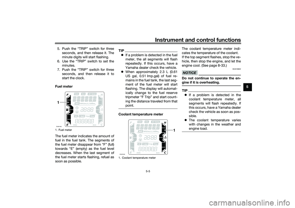
Fuel meter
The fuel meter indicates the amount of
fuel in the fuel tank. The segments of
the fuel meter disappear from “F” (full)
towards “E” (empty) as the fuel level
decreases. When the last segment of
the fuel meter starts flashing, refuel as
soon as possible.
TIP If a problem is detected in the fuel
meter, the all segments will flash
repeatedly. If this occurs, have a
Yamaha dealer check the vehicle.
When approximately 2.3 L (0.61
US gal, 0.51 Imp.gal) of fuel re-
mains in the fuel tank, the last seg-
ment of the fuel meter will start
flashing. The display will automat-
ically change to the fuel reserve
tripmeter “F Trip” and start count-
ing the distance traveled from that
point.Coolant temperature meter The coolant temperature meter indi-
cates the temperature of the coolant.
If the top segment flashes, stop the ve-
hicle, then stop the engine, and let the
engine cool. (See page 8-33.)
NOTICE
ECA10022
Do not continue to operate the en-
g
ine if it is overheatin g.TIP If a problem is detected in the
coolant temperature meter, all
segments will flash repeatedly. If
this occurs, have a Yamaha dealer
check the vehicle as soon as pos-
sible.
The coolant temperature varies
with changes in the weather and
engine load.
1. Fuel meterZAUM14831
1. Coolant temperature meterZAUM1484
1
UB9YE1E0.book Page 5 Tuesday, October 12, 2021 2:29 PM
Page 40 of 118
Instrument and control functions
5-6
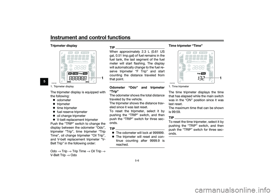
5 Tripmeter
display
The tripmeter display is equipped with
the following: odometer
tripmeter
time tripmeter
fuel reserve tripmeter
oil change tripmeter
V-belt replacement tripmeter
Push the “TRIP” switch to change the
display between the odometer “Odo”,
tripmeter “Trip”, time tripmeter “Trip
Time”, oil change tripmeter “Oil Trip”,
and V-belt replacement tripmeter “V-
Belt Trip” in the following order:
Odo → Trip → Trip Time → Oil Trip →
V-Belt Trip → Odo
TIPWhen approximately 2.3 L (0.61 US
gal, 0.51 Imp.gal) of fuel remains in the
fuel tank, the last segment of the fuel
meter will start flashing. The display
will automatically change to the fuel re-
serve tripmeter “F Trip” and start
counting the distance traveled from
that point.Odometer “O do” an d tripmeter
“Trip”
The odometer shows the total distance
traveled by the vehicle.
The tripmeter shows the distance trav-
eled since it was last reset.
To reset the tripmeter, select it by
pushing the “TRIP” switch, and then
push the “TRIP” switch for three sec-
onds.TIP The odometer will lock at 999999.
The tripmeter will reset and con-
tinue counting after 9999.9 is
reached.
Time tripmeter “Time”
The time tripmeter displays the time
that has elapsed while the main switch
was in the “ON” position since it was
last reset.
The maximum time that can be shown
is 99:59.TIPTo reset the time tripmeter, select it by
pushing the “TRIP” switch, and then
push the “TRIP” switch for three sec-
onds.
1. Tripmeter displayZAUM1485
1
1. Time tripmeterZAUM1486
1
UB9YE1E0.book Page 6 Tuesday, October 12, 2021 2:29 PM