brake YAMAHA XSR 900 2022 User Guide
[x] Cancel search | Manufacturer: YAMAHA, Model Year: 2022, Model line: XSR 900, Model: YAMAHA XSR 900 2022Pages: 114, PDF Size: 4.36 MB
Page 40 of 114

Instrument and control functions
4-17
1
2
34
5
6
7
8
9
10
11
12
13 “Vehicle Setting”
The vehicle setting module allows you
to adjust setting for the BC and quick
shifter.
BC
The brake control system has two set-
tings, BC1 and BC2. Select BC1 when
only standard ABS is desired. Select BC2 to have the brake control system
further regulate brake pressure while
cornering to suppress lateral wheel slip.
TIPFor skilled riders and when riding at the
track, due to varying conditions, the
BC2 brake system may engage sooner
than expected relative to your desired
cornering speed or intended corneringline.
Quick shifterThe quick shifter indicators are divided
into QS and QS sections. QS
and QS are not linked and can be in-
dependently turned on or off.
The quick shifter can be set to ON or
OFF.OFF turns the respective upshift or
downshift function off, and the clutch le-
ver must then be used when shifting in
that direction.
TIPIf the quick shifter setting cannot be
changed: turn the engine off with the
gear position set to neutral, thenchange the setting.
“Shift Indicator”
This module allows a custom shift indi-
cator to be set. When the engine r/min
(rotations per minute) are in the speci-
fied range, the gear indicator will flash.
This module has 3 options:
“IND Mode” - the shift indicator can be
turned ON/OFF
BC SettingQS Setting
km/h
Vehicle Setting
km/h
BC Setting
BC
2
km/h
QS Setting
QS
ONQSON
km/h
Shift Indicator
IND Mode ONIND Start 8000 r/minIND Stop 10000 r/min
BEA-28199-E0.book 17 ページ 2021年12月1日 水曜日 午後7時8分
Page 43 of 114
Instrument and control functions
4-20
1
2
345
6
7
8
9
10
11
12
13
EAU83692
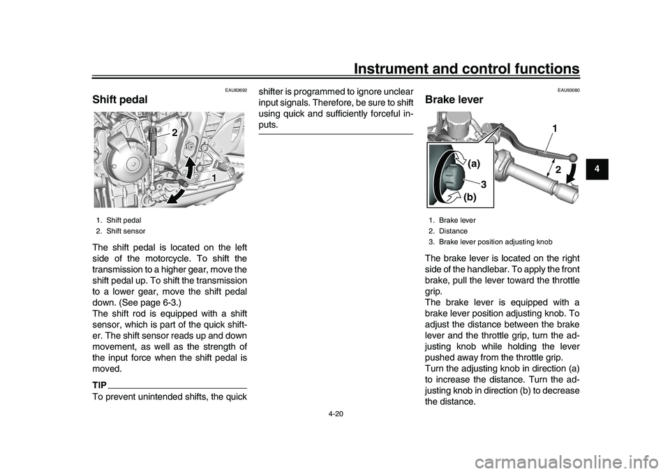
Shift pedalThe shift pedal is located on the left
side of the motorcycle. To shift the
transmission to a higher gear, move the
shift pedal up. To shift the transmission
to a lower gear, move the shift pedal
down. (See page 6-3.)
The shift rod is equipped with a shift
sensor, which is part of the quick shift-
er. The shift sensor reads up and down
movement, as well as the strength of
the input force when the shift pedal is
moved.TIPTo prevent unintended shifts, the quick shifter is programmed to ignore unclear
input signals. Therefore, be sure to shift
using quick and sufficiently forceful in-
puts.
EAU93080
Brake leverThe brake lever is located on the right
side of the handlebar. To apply the front
brake, pull the lever toward the throttle
grip.
The brake lever is equipped with a
brake lever position adjusting knob. To
adjust the distance between the brake
lever and the throttle grip, turn the ad-
justing knob while holding the lever
pushed away from the throttle grip.
Turn the adjusting knob in direction (a)
to increase the distance. Turn the ad-
justing knob in direction (b) to decrease
the distance.
1. Shift pedal
2. Shift sensor
11 1 1
2 2
1. Brake lever
2. Distance
3. Brake lever position adjusting knob
1 1 1
2
2
3 3
(a) (a) (a)
(b) (b) (b)
BEA-28199-E0.book 20 ページ 2021年12月1日 水曜日 午後7時8分
Page 44 of 114
Instrument and control functions
4-21
1
2
34
5
6
7
8
9
10
11
12
13
EAU12944
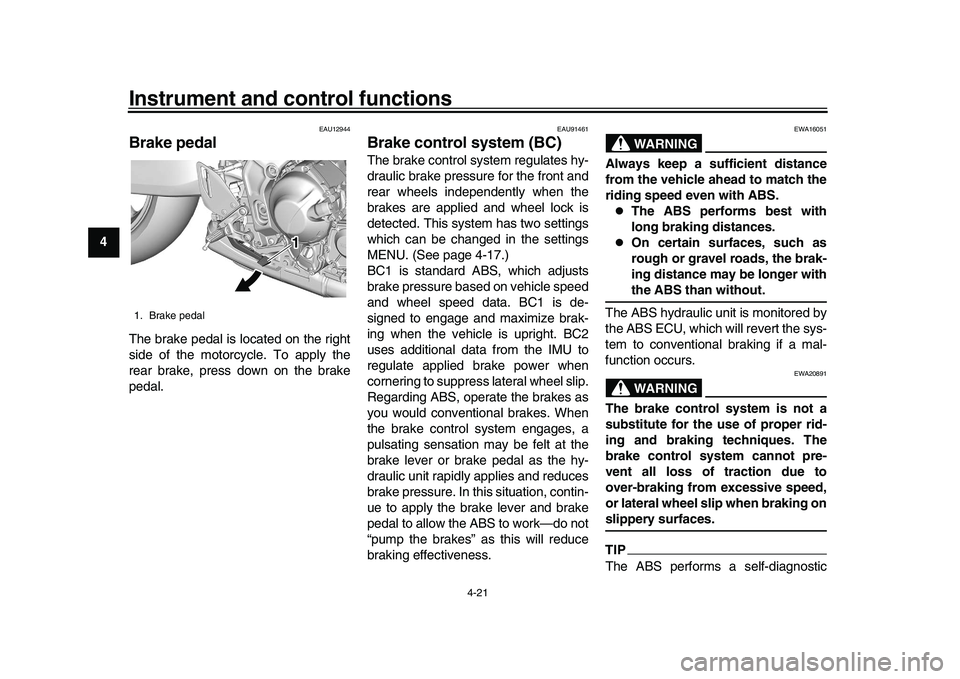
Brake pedalThe brake pedal is located on the right
side of the motorcycle. To apply the
rear brake, press down on the brake
pedal.
EAU91461
Brake control system (BC)The brake control system regulates hy-
draulic brake pressure for the front and
rear wheels independently when the
brakes are applied and wheel lock is
detected. This system has two settings
which can be changed in the settings
MENU. (See page 4-17.)
BC1 is standard ABS, which adjusts
brake pressure based on vehicle speed
and wheel speed data. BC1 is de-
signed to engage and maximize brak-
ing when the vehicle is upright. BC2
uses additional data from the IMU to
regulate applied brake power when
cornering to suppress lateral wheel slip.
Regarding ABS, operate the brakes as
you would conventional brakes. When
the brake control system engages, a
pulsating sensation may be felt at the
brake lever or brake pedal as the hy-
draulic unit rapidly applies and reduces
brake pressure. In this situation, contin-
ue to apply the brake lever and brake
pedal to allow the ABS to work—do not
“pump the brakes” as this will reduce
braking effectiveness.
WARNING
EWA16051
Always keep a sufficient distance
from the vehicle ahead to match the
riding speed even with ABS.
The ABS performs best with
long braking distances.
On certain surfaces, such as
rough or gravel roads, the brak-
ing distance may be longer withthe ABS than without.
The ABS hydraulic unit is monitored by
the ABS ECU, which will revert the sys-
tem to conventional braking if a mal-
function occurs.WARNING
EWA20891
The brake control system is not a
substitute for the use of proper rid-
ing and braking techniques. The
brake control system cannot pre-
vent all loss of traction due to
over-braking from excessive speed,
or lateral wheel slip when braking onslippery surfaces.TIPThe ABS performs a self-diagnostic
1. Brake pedal
11 1 1
BEA-28199-E0.book 21 ページ 2021年12月1日 水曜日 午後7時8分
Page 45 of 114
Instrument and control functions
4-22
1
2
345
6
7
8
9
10
11
12
13
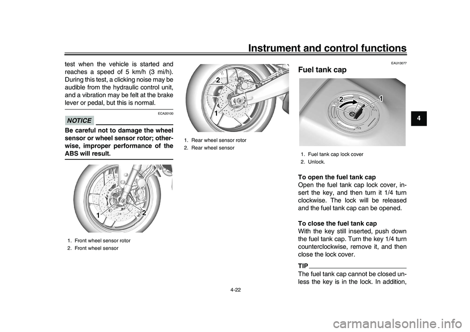
test when the vehicle is started and
reaches a speed of 5 km/h (3 mi/h).
During this test, a clicking noise may be
audible from the hydraulic control unit,
and a vibration may be felt at the brake
lever or pedal, but this is normal.NOTICE
ECA20100
Be careful not to damage the wheel
sensor or wheel sensor rotor; other-
wise, improper performance of theABS will result.
EAU13077
Fuel tank capTo open the fuel tank cap
Open the fuel tank cap lock cover, in-
sert the key, and then turn it 1/4 turn
clockwise. The lock will be released
and the fuel tank cap can be opened.
To close the fuel tank cap
With the key still inserted, push down
the fuel tank cap. Turn the key 1/4 turn
counterclockwise, remove it, and then
close the lock cover.TIPThe fuel tank cap cannot be closed un-
less the key is in the lock. In addition,
1. Front wheel sensor rotor
2. Front wheel sensor
111
22
1. Rear wheel sensor rotor
2. Rear wheel sensor
11122
1. Fuel tank cap lock cover
2. Unlock.
1
2
BEA-28199-E0.book 22 ページ 2021年12月1日 水曜日 午後7時8分
Page 57 of 114
5-1
1
2
3
456
7
8
9
10
11
12
13
For your safety – pre-operation checks
EAU1559B
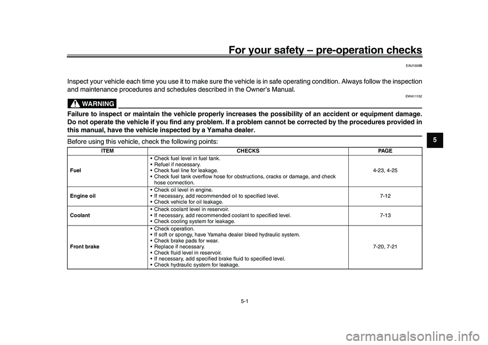
Inspect your vehicle each time you use it to make sure the vehicle is in safe operating condition. Always follow the inspection
and maintenance procedures and schedules described in the Owner’s Manual.
WARNING
EWA11152
Failure to inspect or maintain the vehicle properly increases the possibility of an accident or equipment damage.
Do not operate the vehicle if you find any problem. If a problem cannot be corrected by the procedures provided inthis manual, have the vehicle inspected by a Yamaha dealer.
Before using this vehicle, check the following points:
ITEM CHECKS PAGE
Fuel Check fuel level in fuel tank.
Refuel if necessary.
Check fuel line for leakage.
Check fuel tank overflow hose for obstr
uctions, cracks or damage, and check
hose connection. 4-23, 4-25
Engine oil Check oil level in engine.
If necessary, add recommended oil to specified level.
Check vehicle for oil leakage. 7-12
Coolant Check coolant level in reservoir.
If necessary, add recommended coolant to specified level.
Check cooling system for leakage. 7-13
Front brake Check operation.
If soft or spongy, have Yamaha dealer bleed hydraulic system.
Check brake pads for wear.
Replace if necessary.
Check fluid level in reservoir.
If necessary, add specified brake fluid to specified level.
Check hydraulic system for leakage. 7-20, 7-21
BEA-28199-E0.book 1 ページ 2021年12月1日 水曜日 午後7時8分
Page 58 of 114
For your safety – pre-operation checks
5-2
1
2
3
45
6
7
8
9
10
11
12
13
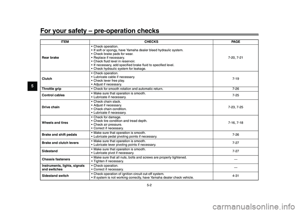
Rear brake Check operation.
If soft or spongy, have Yamaha dealer bleed hydraulic system.
Check brake pads for wear.
Replace if necessary.
Check fluid level in reservoir.
If necessary, add specified brake fluid to specified level.
Check hydraulic system for leakage. 7-20, 7-21
Clutch Check operation.
Lubricate cable if necessary.
Check lever free play.
Adjust if necessary. 7-19
Throttle grip Check for smooth rotation and automatic return. 7-26
Control cables Make sure that operation is smooth.
Lubricate if necessary. 7-25
Drive chain Check chain slack.
Adjust if necessary.
Check chain condition.
Lubricate if necessary. 7-23, 7-25
Wheels and tires Check for damage.
Check tire condition and tread depth.
Check air pressure.
Correct if necessary. 7-16, 7-18
Brake and shift pedals Make sure that operation is smooth.
Lubricate pedal pivoting points if necessary. 7-26
Brake and clutch levers Make sure that operation is smooth.
Lubricate lever pivoting points if necessary. 7-27
Sidestand Make sure that operation is smooth.
Lubricate pivot if necessary. 7-27
Chassis fasteners Make sure that all nuts, bolts
and screws are properly tightened.
Tighten if necessary. —
Instruments, lights, signals
and switches Check operation.
Correct if necessary.
—
Sidestand switch Check operation of ignition circuit cut-off system.
If system is not working correctly, have Yamaha dealer check vehicle. 4-31
ITEM CHECKS PAGE
BEA-28199-E0.book 2 ページ 2021年12月1日 水曜日 午後7時8分
Page 62 of 114
Operation and important riding points
6-4
1
2
3
4
56
7
8
9
10
11
12
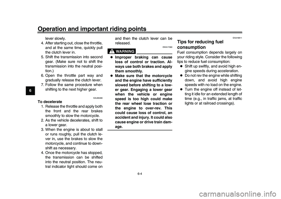
13 lever slowly.
4. After starting out, close the throttle, and at the same time, quickly pull
the clutch lever in.
5. Shift the transmission into second gear. (Make sure not to shift the
transmission into the neutral posi-
tion.)
6. Open the throttle part way and gradually release the clutch lever.
7. Follow the same procedure when shifting to the next higher gear.
EAU85380
To decelerate1. Release the throttle and apply both the front and the rear brakes
smoothly to slow the motorcycle.
2. As the vehicle decelerates, shift to a lower gear.
3. When the engine is about to stall or runs roughly, pull the clutch le-
ver in, use the brakes to slow the
motorcycle, and continue to down-
shift as necessary.
4. Once the motorcycle has stopped, the transmission can be shifted
into the neutral position. The neu-
tral indicator light should come on and then the clutch lever can be
released.
WARNING
EWA17380
Improper braking can cause
loss of control or traction. Al-
ways use both brakes and apply
them smoothly.
Make sure that the motorcycle
and the engine have sufficiently
slowed before shifting to a low-
er gear. Engaging a lower gear
when the vehicle or engine
speed is too high could make
the rear wheel lose traction or
the engine to over-rev. This
could cause loss of control, an
accident and injury. It could also
cause engine or drive train dam-age.
EAU16811
Tips for reducing fuel
consumptionFuel consumption depends largely on
your riding style. Consider the following
tips to reduce fuel consumption:
Shift up swiftly, and avoid high en-
gine speeds during acceleration.
Do not rev the engine while shifting
down, and avoid high engine
speeds with no load on the engine.
Turn the engine off instead of let-
ting it idle for an extended length of
time (e.g., in traffic jams, at traffic
lights or at railroad crossings).
BEA-28199-E0.book 4 ページ 2021年12月1日 水曜日 午後7時8分
Page 64 of 114

7-1
1
2
3
4
5
67
8
9
10
11
12
13
Periodic maintenance and adjustment
EAU17246
Periodic inspection, adjustment, and lu-
brication will keep your vehicle in the
safest and most efficient condition pos-
sible. Safety is an obligation of the vehi-
cle owner/operator. The most important
points of vehicle inspection, adjust-
ment, and lubrication are explained on
the following pages.
The intervals given in the periodic
maintenance charts should be simply
considered as a general guide under
normal riding conditions. However, de-
pending on the weather, terrain, geo-
graphical location, and individual use,
the maintenance intervals may need to
be shortened.
WARNING
EWA10322
Failure to properly maintain the ve-
hicle or performing maintenance ac-
tivities incorrectly may increase
your risk of injury or death during
service or while using the vehicle. If
you are not familiar with vehicle ser-
vice, have a Yamaha dealer performservice.
WARNING
EWA15123
Turn off the engine when performing
maintenance unless otherwise
specified.
A running engine has moving
parts that can catch on body
parts or clothing and electrical
parts that can cause shocks or
fires.
Running the engine while ser-
vicing can lead to eye injury,
burns, fire, or carbon monoxide
poisoning – possibly leading to
death. See page 1-2 for more in-
formation about carbon monox-ide.WARNING
EWA15461
Brake discs, calipers, drums, and
linings can become very hot during
use. To avoid possible burns, let
brake components cool beforetouching them.
EAU17303
Emission controls not only function to
ensure cleaner air, but are also vital to
proper engine operation and maximum
performance. In the following periodic
maintenance charts, the services relat-
ed to emissions control are grouped
separately. These services require
specialized data, knowledge, and
equipment. Maintenance, replacement,
or repair of the emission control devic-
es and systems may be performed by
any repair establishment or individual
that is certified (if applicable). Yamaha
dealers are trained and equipped to
perform these particular services.
BEA-28199-E0.book 1 ページ 2021年12月1日 水曜日 午後7時8分
Page 67 of 114
Periodic maintenance and adjustment
7-4
1
2
3
4
5
678
9
10
11
12
13
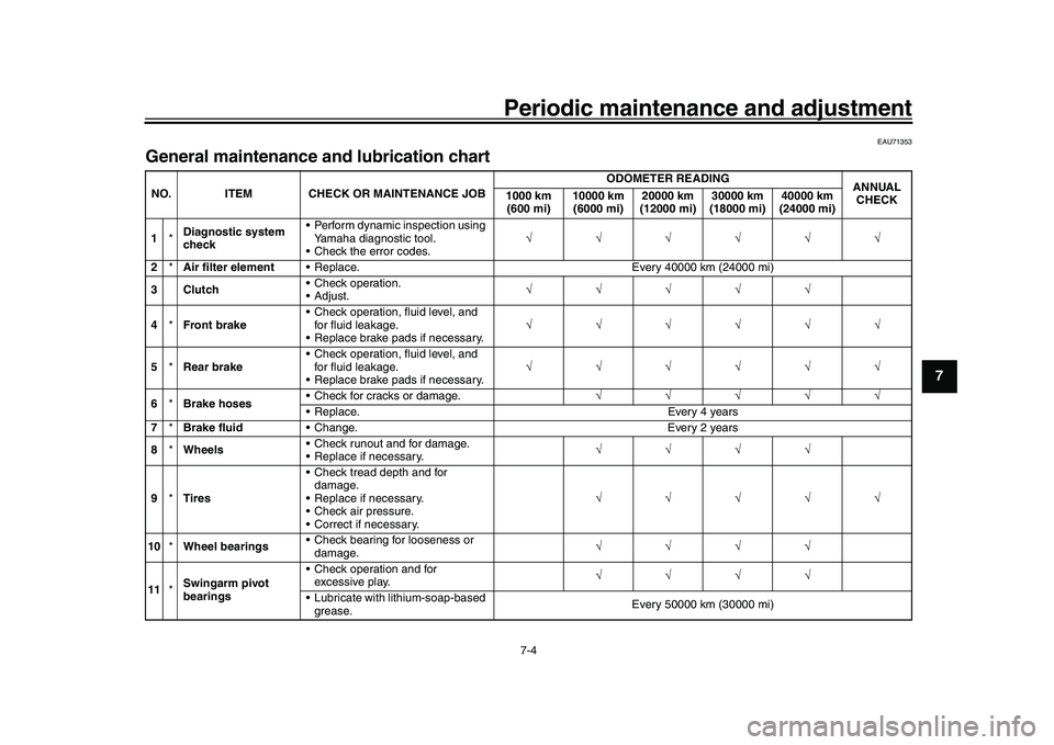
EAU71353
General maintenance an d lubrication chartNO. ITEM CHECK OR MAINTENANCE JOB ODOMETER READING
ANNUAL
CHECK
1000 km
(600 mi) 10000 km
(6000 mi) 20000 km
(12000 mi) 30000 km
(18000 mi) 40000 km
(24000 mi)
1 *Diagnostic system
check Perform dynamic inspection using
Yamaha diagnostic tool.
Check the error codes.
2 *Air filter element Replace. Every 40000 km (24000 mi)
3Clutch Check operation.
Adjust.
4 *Front brake Check operation, fluid level, and
for fluid leakage.
Replace brake pads if necessary.
5 *Rear brake Check operation, fluid level, and
for fluid leakage.
Replace brake pads if necessary.
6 *Brake hoses Check for cracks or damage.
Replace. Every 4 years
7 *Brake fluid Change. Every 2 years
8 *Wheels Check runout and for damage.
Replace if necessary.
9 *Tires Check tread depth and for
damage.
Replace if necessary.
Check air pressure.
Correct if necessary.
10 *Wheel bearings Check bearing for looseness or
damage.
11 *Swingarm pivot
bearings Check operation and for
excessive play.
Lubricate with lithium-soap-based grease. Every 50000 km (30000 mi)
BEA-28199-E0.book 4 ページ 2021年12月1日 水曜日 午後7時8分
Page 68 of 114
Periodic maintenance and adjustment
7-5
1
2
3
4
5
67
8
9
10
11
12
13
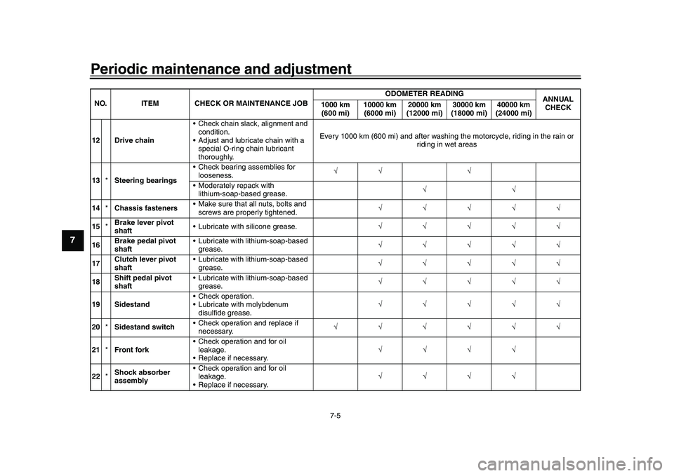
12 Drive chain Check chain slack, alignment and
condition.
Adjust and lubricate chain with a special O-ring chain lubricant
thoroughly. Every 1000 km (600 mi) and after washing the motorcycle, riding in the rain or
riding in wet areas
13 *Steering bearings Check bearing assemblies for
looseness.
Moderately repack with lithium-soap-based grease.
14 *Chassis fasteners Make sure that all nuts, bolts and
screws are properly tightened.
15 *Brake lever pivot
shaft Lubricate with silicone grease.
16 Brake pedal pivot
shaft Lubricate with lithium-soap-based
grease.
17 Clutch lever pivot
shaft Lubricate with lithium-soap-based
grease.
18 Shift pedal pivot
shaft Lubricate with lithium-soap-based
grease.
19 Sidestand Check operation.
Lubricate with molybdenum
disulfide grease.
20 *Sidestand switch Check operation and replace if
necessary.
21 *Front fork Check operation and for oil
leakage.
Replace if necessary.
22 *Shock absorber
assembly Check operation and for oil
leakage.
Replace if necessary.
NO. ITEM CHECK OR MAINTENANCE JOB
ODOMETER READING
ANNUAL
CHECK
1000 km
(600 mi) 10000 km
(6000 mi) 20000 km
(12000 mi) 30000 km
(18000 mi) 40000 km
(24000 mi)BEA-28199-E0.book 5 ページ 2021年12月1日 水曜日 午後7時8分