handlebar YAMAHA XSR 900 2022 User Guide
[x] Cancel search | Manufacturer: YAMAHA, Model Year: 2022, Model line: XSR 900, Model: YAMAHA XSR 900 2022Pages: 114, PDF Size: 4.36 MB
Page 43 of 114

Instrument and control functions
4-20
1
2
345
6
7
8
9
10
11
12
13
EAU83692
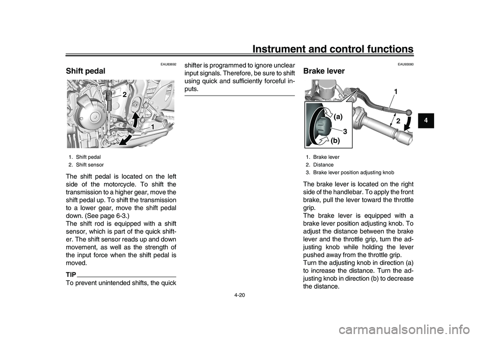
Shift pedalThe shift pedal is located on the left
side of the motorcycle. To shift the
transmission to a higher gear, move the
shift pedal up. To shift the transmission
to a lower gear, move the shift pedal
down. (See page 6-3.)
The shift rod is equipped with a shift
sensor, which is part of the quick shift-
er. The shift sensor reads up and down
movement, as well as the strength of
the input force when the shift pedal is
moved.TIPTo prevent unintended shifts, the quick shifter is programmed to ignore unclear
input signals. Therefore, be sure to shift
using quick and sufficiently forceful in-
puts.
EAU93080
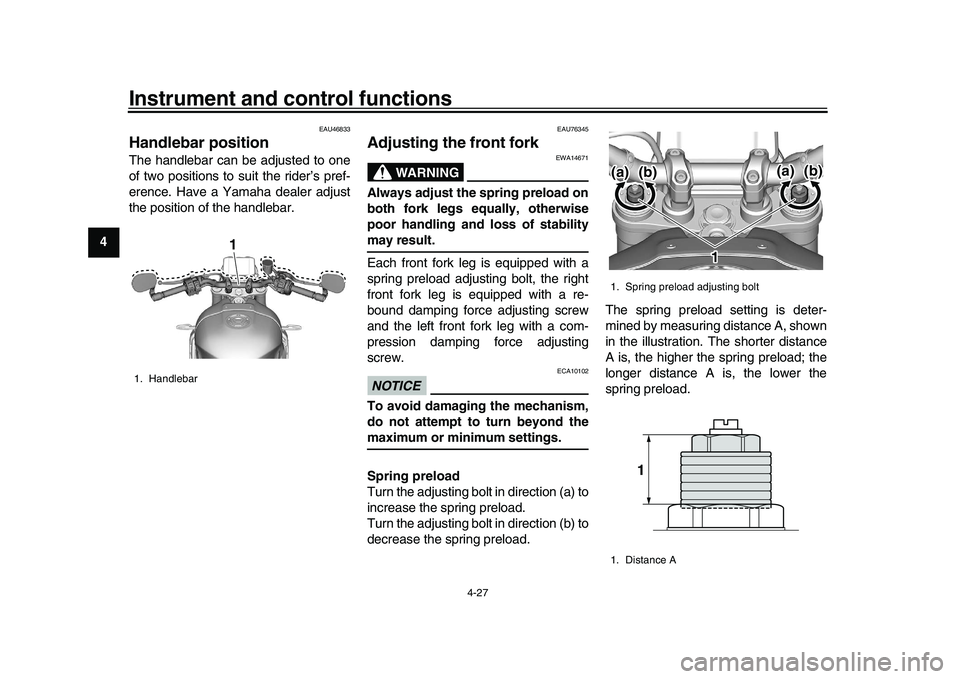
Brake leverThe brake lever is located on the right
side of the handlebar. To apply the front
brake, pull the lever toward the throttle
grip.
The brake lever is equipped with a
brake lever position adjusting knob. To
adjust the distance between the brake
lever and the throttle grip, turn the ad-
justing knob while holding the lever
pushed away from the throttle grip.
Turn the adjusting knob in direction (a)
to increase the distance. Turn the ad-
justing knob in direction (b) to decrease
the distance.
1. Shift pedal
2. Shift sensor
11 1 1
2 2
1. Brake lever
2. Distance
3. Brake lever position adjusting knob
1 1 1
2
2
3 3
(a) (a) (a)
(b) (b) (b)
BEA-28199-E0.book 20 ページ 2021年12月1日 水曜日 午後7時8分
Page 50 of 114

Instrument and control functions
4-27
1
2
34
5
6
7
8
9
10
11
12
13
EAU46833
Handlebar position The handlebar can be adjusted to one
of two positions to suit the rider’s pref-
erence. Have a Yamaha dealer adjust
the position of the handlebar.
EAU76345
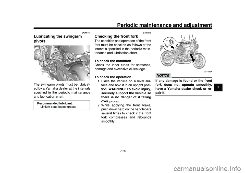
Adjusting the front fork
WARNING
EWA14671
Always adjust the spring preload on
both fork legs equally, otherwise
poor handling and loss of stabilitymay result.
Each front fork leg is equipped with a
spring preload adjusting bolt, the right
front fork leg is equipped with a re-
bound damping force adjusting screw
and the left front fork leg with a com-
pression damping force adjusting
screw.NOTICE
ECA10102
To avoid damaging the mechanism,
do not attempt to turn beyond themaximum or minimum settings.
Spring preload
Turn the adjusting bolt in direction (a) to
increase the spring preload.
Turn the adjusting bolt in direction (b) to
decrease the spring preload. The spring preload setting is deter-
mined by measuring distance A, shown
in the illustration. The shorter distance
A is, the higher the spring preload; the
longer distance A is, the lower the
spring preload.
1. Handlebar
1 1 1
1. Spring preload adjusting bolt
1. Distance A
(b)
1
11
(a)
(b)(a)
1
BEA-28199-E0.book 27 ページ 2021年12月1日 水曜日 午後7時8分
Page 91 of 114

Periodic maintenance and adjustment7-28
1
2
3
4
5
678
9
10
11
12
13
EAUM1653
Lubricating the swingarm
pivotsThe swingarm pivots must be lubricat-
ed by a Yamaha dealer at the intervals
specified in the periodic maintenance
and lubrication chart.
EAU23273
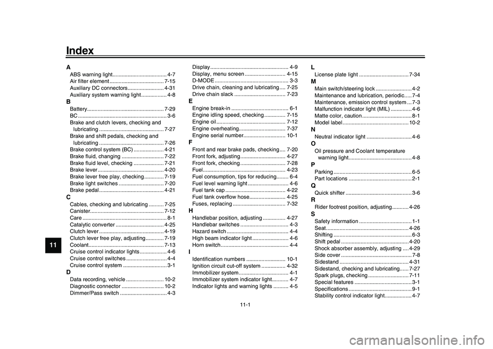
Checking the front forkThe condition and operation of the front
fork must be checked as follows at the
intervals specified in the periodic main-
tenance and lubrication chart.
To check the condition
Check the inner tubes for scratches,
damage and excessive oil leakage.
To check the operation 1. Place the vehicle on a level sur- face and hold it in an upright posi-
tion. WARNING! To avoid injury,
securely support the vehicle so
there is no danger of it falling
over.
[EWA10752]
2. While applying the front brake, push down hard on the handlebars
several times to check if the front
fork compresses and rebounds
smoothly.
NOTICE
ECA10591
If any damage is found or the front
fork does not operate smoothly,
have a Yamaha dealer check or re-pair it.
Recommended lubricant:Lithium-soap-based grease
BEA-28199-E0.book 28 ページ 2021年12月1日 水曜日 午後7時8分
Page 110 of 114

11-1
1
2
3
4
5
6
7
8
9
1011
12
13
IndexAABS warning light.................................... 4-7
Air filter element .................................... 7-15
Auxiliary DC connectors........................ 4-31
Auxiliary system warning light ................. 4-8BBattery................................................... 7-29
BC ........................................................... 3-6
Brake and clutch levers, checking and lubricating ........................................... 7-27
Brake and shift pedals, checking and lubricating ........................................... 7-26
Brake control system (BC) .................... 4-21
Brake fluid, changing ............................ 7-22
Brake fluid level, checking .................... 7-21
Brake lever ............................................ 4-20
Brake lever free play, checking ............. 7-19
Brake light switches .............................. 7-20
Brake pedal ........................................... 4-21CCables, checking and lubricating .......... 7-25
Canister................................................. 7-12
Care ........................................................ 8-1
Catalytic converter ................................ 4-25
Clutch lever ........................................... 4-19
Clutch lever free play, adjusting ............ 7-19
Coolant.................................................. 7-13
Cruise control indicator lights .................. 4-6
Cruise control switches ........................... 4-4
Cruise control system ............................. 3-1DData recording, vehicle ......................... 10-2
Diagnostic connector ............................ 10-2
Dimmer/Pass switch ............................... 4-3 Display .................................................... 4-9
Display, menu screen ........................... 4-15
D-MODE ................................................. 3-3
Drive chain, cleaning and lubricating .... 7-25
Drive chain slack .................................. 7-23
EEngine break-in ...................................... 6-1
Engine idling speed, checking .............. 7-15
Engine oil .............................................. 7-12
Engine overheating............................... 7-37
Engine serial number............................ 10-1FFront and rear brake
pads, checking .... 7-20
Front fork, adjusting .............................. 4-27
Front fork, checking .............................. 7-28
Fuel....................................................... 4-23
Fuel consumption, tips for reducing........ 6-4
Fuel level warning light ........................... 4-6
Fuel tank cap ........................................ 4-22
Fuel tank overflow hose........................ 4-25
Fuses, replacing ................................... 7-32HHandlebar position, adjusting ............... 4-27
Handlebar switches ................................ 4-3
Hazard switch ......................................... 4-4
High beam indicator light ........................ 4-6
Horn switch ............................................. 4-4IIdentification numbers .......................... 10-1
Ignition circuit cut-off system ................ 4-32
Immobilizer system ................................. 4-1
Immobilizer system indicator light........... 4-7
Indicator lights and warning lights .......... 4-5
LLicense plate light ................................. 7-34MMain switch/steering lock ........................ 4-2
Maintenance and lubrication, periodic..... 7-4
Maintenance, emission control system ... 7-3
Malfunction indicator light (MIL) .............. 4-6
Matte color, caution ................................. 8-1
Model label ............................................ 10-2NNeutral indicator light .............................. 4-6OOil pressure and Coolant temperature warning light.......................................... 4-8PParking .................................................... 6-5
Part locations .......................................... 2-1QQuick shifter ............................................ 3-6RRider footrest position, adjusting ........... 4-26SSafety information ................................... 1-1
Seat ....................................................... 4-26
Shifting .................................................... 6-3
Shift pedal ............................................. 4-20
Shock absorber assembly, adjusting .... 4-29
Side cover ............................................... 7-8
Sidestand .............................................. 4-31
Sidestand, checking an d lubricating...... 7-27
Spark plugs, checking ........................... 7-11
Special features ...................................... 3-1
Specifications .......................................... 9-1
Stability control indicator light.................. 4-7
BEA-28199-E0.book 1 ページ 2021年12月1日 水曜日 午後7時8分