lock YAMAHA XT660Z 2010 Owners Manual
[x] Cancel search | Manufacturer: YAMAHA, Model Year: 2010, Model line: XT660Z, Model: YAMAHA XT660Z 2010Pages: 100, PDF Size: 6.91 MB
Page 6 of 100
TABLE OF CONTENTS
LOCATION OF IMPORTANT LABELS...1-1
SAFETY INFORMATION.....................2-1
Be a Responsible Owner ..................2-1
Safe riding .........................................2-1
Protective apparel .............................2-2
Avoid Carbon Monoxide Poisoning ...2-2
Loading .............................................2-3
Genuine Yamaha Accessories ..........2-3
Aftermarket Parts, Accessories,
and Modifications .......................2-4
Aftermarket Tires and Rims ..............2-4
DESCRIPTION.....................................3-1
Left view ............................................3-1
Right view .........................................3-2
Controls and instruments ..................3-3
INSTRUMENT AND CONTROL
FUNCTIONS........................................4-1
Immobilizer system ...........................4-1
Main switch/steering lock ..................4-2
Indicator and warning lights ..............4-3
Multi-function display ........................4-5
Tachometer .......................................4-6
Tripmeter and tachometer modes .....4-6
Clock mode .......................................4-7
Fuel meter .........................................4-7
Self-diagnosis devices ......................4-7Handlebar switches ...........................4-9
Clutch lever .....................................4-10
Shift pedal .......................................4-10
Brake lever ......................................4-11
Brake pedal .....................................4-11
Fuel tank cap ..................................4-11
Fuel .................................................4-12
Fuel tank breather hose ..................4-13
Catalytic converter ..........................4-13
Seat .................................................4-14
Adjusting the front fork ....................4-15
Adjusting the shock absorber
assembly ..................................4-16
Sidestand ........................................4-17
Ignition circuit cut-off system ..........4-17
FOR YOUR SAFETY -
PRE-OPERATION CHECKS...............5-1
Pre-operation check list ....................5-2
OPERATION AND IMPORTANT
RIDING POINTS..................................6-1
Starting the engine............................6-1
Shifting ..............................................6-2
Tips for reducing fuel consumption ...6-3
Engine break-in .................................6-3
Parking ..............................................6-4PERIODIC MAINTENANCE AND
ADJUSTMENT.....................................7-1
Owner’s tool kit .................................7-1
Periodic maintenance chart for
the emission control system.......7-2
General maintenance
and lubrication chart ..................7-3
Removing and installing
the cowling and panels ..............7-8
Checking the spark plug ...................7-8
Engine oil and oil filter element.........7-9
Coolant ............................................7-12
Replacing the air filter element
and cleaning the check hose ...7-14
Checking the engine idling speed ...7-15
Checking the throttle cable
free play ...................................7-16
Valve clearance ...............................7-16
Tires ................................................7-16
Spoke wheels..................................7-19
Adjusting the clutch lever free play...7-20
Checking the front and rear
brake pads ...............................7-21
Checking the brake fluid level .........7-22
Changing the brake fluid .................7-23
Drive chain slack .............................7-23
Cleaning and lubricating
the drive chain ..........................7-25
XT660Z 01-03 ING-AUS:AUSTRALIA 11-05-2009 9:57 Pagina 6
Page 14 of 100
3-1
1
2
3
4
5
6
7
8
9
10
DESCRIPTION
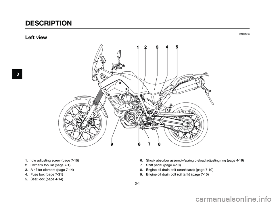
EAU10410Left view
1. Idle adjusting screw (page 7-15)
2. Owner’s tool kit (page 7-1)
3. Air filter element (page 7-14)
4. Fuse box (page 7-31)
5. Seat lock (page 4-14)6. Shock absorber assembly/spring preload adjusting ring (page 4-16)
7. Shift pedal (page 4-10)
8. Engine oil drain bolt (crankcase) (page 7-10)
9. Engine oil drain bolt (oil tank) (page 7-10)
XT660Z 01-03 ING-AUS:AUSTRALIA 11-05-2009 9:57 Pagina 14
Page 16 of 100
DESCRIPTION
3-3
1
2
3
4
5
6
7
8
9
10
EAU10430
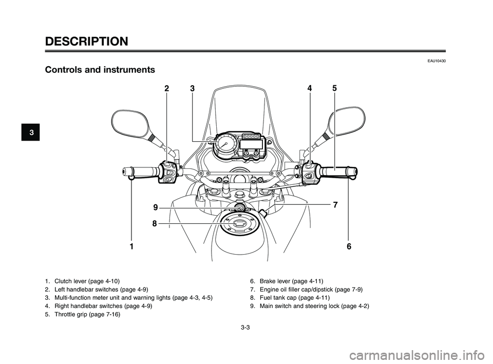
Controls and instruments
1. Clutch lever (page 4-10)
2. Left handlebar switches (page 4-9)
3. Multi-function meter unit and warning lights (page 4-3, 4-5)
4. Right handlebar switches (page 4-9)
5. Throttle grip (page 7-16)6. Brake lever (page 4-11)
7. Engine oil filler cap/dipstick (page 7-9)
8. Fuel tank cap (page 4-11)
9. Main switch and steering lock (page 4-2)
XT660Z 01-03 ING-AUS:AUSTRALIA 11-05-2009 9:57 Pagina 16
Page 18 of 100
INSTRUMENT AND CONTROL FUNCTIONS
4-2
1
2
3
4
5
6
7
8
9
10
EAU10471
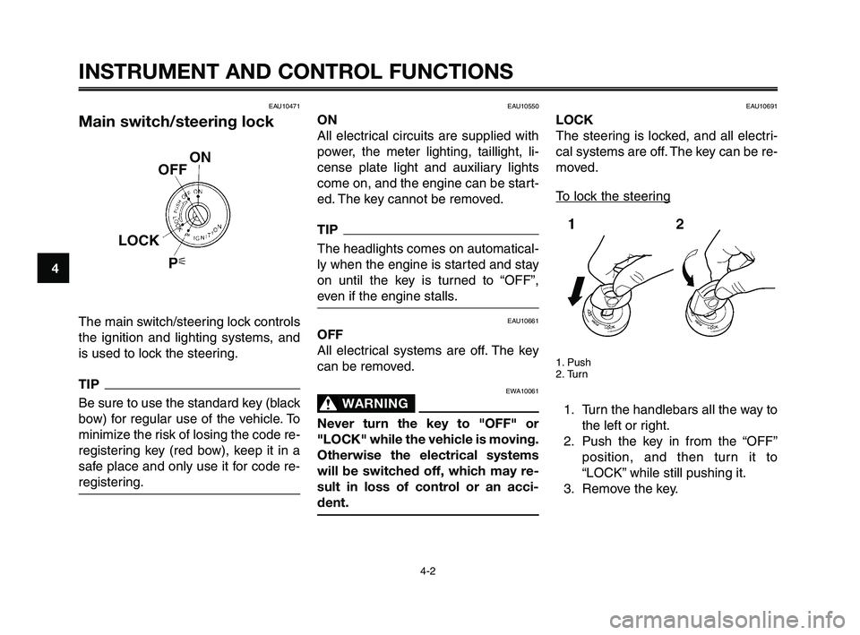
Main switch/steering lock
The main switch/steering lock controls
the ignition and lighting systems, and
is used to lock the steering.
TIP
Be sure to use the standard key (black
bow) for regular use of the vehicle. To
minimize the risk of losing the code re-
registering key (red bow), keep it in a
safe place and only use it for code re-
registering.
EAU10550
ON
All electrical circuits are supplied with
power, the meter lighting, taillight, li-
cense plate light and auxiliary lights
come on, and the engine can be start-
ed. The key cannot be removed.
TIP
The headlights comes on automatical-
ly when the engine is started and stay
on until the key is turned to “OFF”,
even if the engine stalls.
EAU10661
OFF
All electrical systems are off. The key
can be removed.
EWA10061
WARNING0
Never turn the key to "OFF" or
"LOCK" while the vehicle is moving.
Otherwise the electrical systems
will be switched off, which may re-
sult in loss of control or an acci-
dent.
EAU10691
LOCK
The steering is locked, and all electri-
cal systems are off. The key can be re-
moved.
To lock the steering
1. Push
2. Turn
1. Turn the handlebars all the way to
the left or right.
2. Push the key in from the “OFF”
position, and then turn it to
“LOCK” while still pushing it.
3. Remove the key.
XT660Z 04-04 ING-AUS:MY03 01-03 ING 11-05-2009 9:54 Pagina 4-2
Page 19 of 100
1
2
3
4
5
6
7
8
9
10
INSTRUMENT AND CONTROL FUNCTIONS
4-3
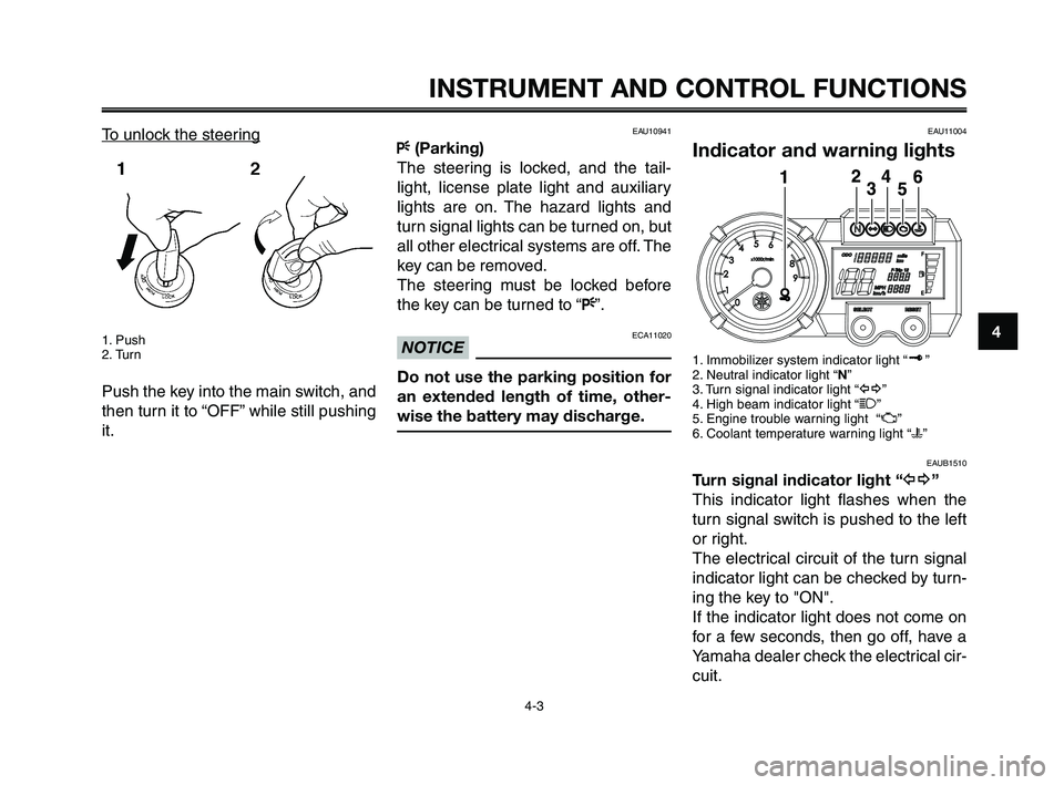
To unlock the steering
1. Push
2. Turn
Push the key into the main switch, and
then turn it to “OFF” while still pushing
it.
EAU10941
F(Parking)
The steering is locked, and the tail-
light, license plate light and auxiliary
lights are on. The hazard lights and
turn signal lights can be turned on, but
all other electrical systems are off. The
key can be removed.
The steering must be locked before
the key can be turned to “F”.
ECA11020NOTICE
Do not use the parking position for
an extended length of time, other-
wise the battery may discharge.
EAU11004
Indicator and warning lights
1. Immobilizer system indicator light “ ”
2. Neutral indicator light “N”
3. Turn signal indicator light “y”
4. High beam indicator light “1”
5. Engine trouble warning light “U”
6. Coolant temperature warning light “u”
EAUB1510
Turn signal indicator light “y”
This indicator light flashes when the
turn signal switch is pushed to the left
or right.
The electrical circuit of the turn signal
indicator light can be checked by turn-
ing the key to "ON".
If the indicator light does not come on
for a few seconds, then go off, have a
Yamaha dealer check the electrical cir-
cuit.
XT660Z 04-04 ING-AUS:MY03 01-03 ING 11-05-2009 9:54 Pagina 4-3
Page 21 of 100

1
2
3
4
5
6
7
8
9
10
INSTRUMENT AND CONTROL FUNCTIONS
4-5
EAUB1501
Multi-function display
1. Tachometer
2. Speedometer
3. Odometer
4. Tripmeters/Fuel reserve tripmeter
5. Clock
6. Fuel meter
7. “RESET” button
8. “SELECT” button
EWA12311
WARNING0
Be sure to stop the vehicle before
making any setting changes to the
multi-function display.
The multi-function display is equipped
with the following:
●a speedometer (which shows the
riding speed)
●a digital tachometer (which shows
engine r/min)
●an odometer (which shows the to-
tal distance traveled)
●two tripmeters (which show the
distance traveled since they were
last set to zero)
●a fuel reserve tripmeter (which
shows the distance traveled since
the bottom segment of the fuel
meter started flashing)
●a clock
●a fuel meter
●a self-diagnosis device
TIP
●Be sure to turn the key to "ON"
before using the "SELECT" and
"RESET" buttons.
●For the U.K. only: To switch the
speedometer and odome-
ter/tripmeter displays between
kilometers and miles, push the
"SELECT" and "RESET" buttons
together and turn the key to "ON".
When the digits start flashing,
push the "SELECT" button to
choose kilometers or miles.
XT660Z 04-04 ING-AUS:MY03 01-03 ING 11-05-2009 9:54 Pagina 4-5
Page 23 of 100

1
2
3
4
5
6
7
8
9
10
INSTRUMENT AND CONTROL FUNCTIONS
4-7
Clock mode
1. Clock
2. “SELECT” button
3. “RESET” button
TIP
The clock is displayed even when the
key is turned to "OFF".
To set the clock:
1. Push the "SELECT" button for at
least four seconds.
2. When the hour digits start flash-
ing, push the "RESET" button to
set the hours.
3. Push the "SELECT" button, and
the minute digits will start flashing.
4. Push the "RESET" button to set
the minutes.
5. Push the "SELECT" button and
then release it to start the clock.
Fuel meter
1. Fuel meter
With the key in the "ON" position, the
fuel meter indicates the amount of fuel
in the fuel tank. When the key is turned
to "ON", all of the display segments of
the fuel meter will appear one after the
other and then disappear in order to
test the electrical circuit. The display
segments of the fuel meter disappear
towards "E" (Empty) as the fuel level
decreases. When only one segment is
left near "E" (Empty), refuel as soon
as possible.
TIP
This fuel meter is equipped with a self-
diagnosis system. If the electrical cir-
cuit is defective, all the segments will
start flashing. If this occurs, have a
Yamaha dealer check the electrical cir-
cuit.
XT660Z 04-04 ING-AUS:MY03 01-03 ING 11-05-2009 9:54 Pagina 4-7
Page 27 of 100

1
2
3
4
5
6
7
8
9
10
INSTRUMENT AND CONTROL FUNCTIONS
4-11
EAU26823
Brake lever
1. Brake lever
2. Position adjusting dial
3. Arrow mark
4. Distance
The brake lever is located at the right
handlebar grip. To apply the front
brake, pull the lever toward the han-
dlebar grip.
The brake lever is equipped with a po-
sition adjusting dial. To adjust the dis-
tance between the brake lever and the
handlebar grip, turn the adjusting dial
while holding the lever pushed away
from the handlebar grip. Make sure
that the appropriate setting on the ad-
justing dial is aligned with the “˙”
mark on the brake lever.
EAU12941
Brake pedal
1. Brake pedal
The brake pedal is on the right side of
the motorcycle. To apply the rear
brake, press down on the brake pedal.
1
EAU13074
Fuel tank cap
1. Lock cover
2. Open
To open the fuel tank cap
Open the fuel tank cap lock cover, in-
sert the key into the lock, and then turn
it 1/4 turn clockwise. The lock will be re-
leased and the fuel tank cap can be
opened.
XT660Z 04-04 ING-AUS:MY03 01-03 ING 11-05-2009 9:54 Pagina 4-11
Page 28 of 100
INSTRUMENT AND CONTROL FUNCTIONS
4-12
1
2
3
4
5
6
7
8
9
10
To close the fuel tank cap
1. Push the fuel tank cap into posi-
tion with the key inserted in the
lock.
2. Turn the key counterclockwise to
the original position, remove it,
and then close the lock cover.
TIP
The fuel tank cap cannot be closed
unless the key is in the lock. In addi-
tion, the key cannot be removed if the
cap is not properly closed and locked.
EWA11091
WARNING0
Make sure that the fuel tank cap is
properly closed after filling fuel.
Leaking fuel is a fire hazard.
EAU13221
Fuel
Make sure there is sufficient gasoline
in the tank.
EWA10881
WARNING0
Gasoline and gasoline vapors are
extremely flammable. To avoid fires
and explosions and to reduce the
risk of injury when refueling, follow
these instructions.
1. Before refueling, turn off the en-
gine and be sure that no one is
sitting on the vehicle. Never refuel
while smoking, or while in the
vicinity of sparks, open flames, or
other sources of ignition such as
the pilot lights of water heaters
and clothes dryers.
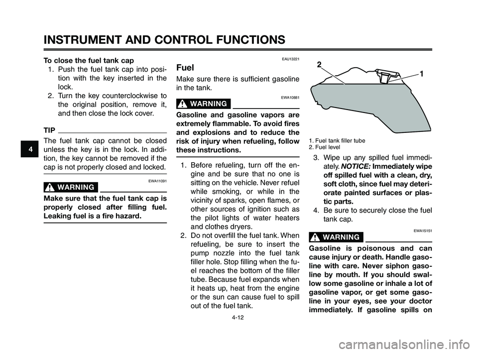
2. Do not overfill the fuel tank. When
refueling, be sure to insert the
pump nozzle into the fuel tank
filler hole. Stop filling when the fu-
el reaches the bottom of the filler
tube. Because fuel expands when
it heats up, heat from the engine
or the sun can cause fuel to spill
out of the fuel tank.
1. Fuel tank filler tube
2. Fuel level
3. Wipe up any spilled fuel immedi-
ately. NOTICE:Immediately wipe
off spilled fuel with a clean, dry,
soft cloth, since fuel may deteri-
orate painted surfaces or plas-
tic parts.
4. Be sure to securely close the fuel
tank cap.
EWA15151
WARNING0
Gasoline is poisonous and can
cause injury or death. Handle gaso-
line with care. Never siphon gaso-
line by mouth. If you should swal-
low some gasoline or inhale a lot of
gasoline vapor, or get some gaso-
line in your eyes, see your doctor
immediately. If gasoline spills on
XT660Z 04-04 ING-AUS:MY03 01-03 ING 11-05-2009 9:54 Pagina 4-12
Page 29 of 100

1
2
3
4
5
6
7
8
9
10
INSTRUMENT AND CONTROL FUNCTIONS
4-13
your skin, wash with soap and wa-
ter. If gasoline spills on your cloth-
ing, change your clothes.
EAU13390EAU13412
Fuel tank breather hose
1. Fuel tank breather hose
2. Clamp
Before operating the motorcycle:
●Check the fuel tank breather hose
connection.
●Check the fuel tank breather hose
for cracks or damage, and replace
it if damaged.
●Make sure that the fuel tank
breather hose is not blocked, and
clean it if necessary.
ECA11400
NOTICE
Use only unleaded gasoline. The use
of leaded gasoline will cause severe
damage to internal engine parts,
such as the valves and piston rings,
as well as to the exhaust system.
Your Yamaha engine has been de-
signed to use premium unleaded
gasoline with a research octane num-
ber of 95 or higher. If knocking (or
pinging) occurs, use a gasoline of a
different brand. Use of unleaded fuel
will extend spark plug life and reduce
maintenance costs.
Recommended fuel:
PREMIUM UNLEADED
GASOLINE ONLY
Fuel tank capacity:
23.0 L (6.07 US gal) (5.05 Imp.gal)
Fuel reserve amount (when the fuel
level warning light comes on):
6.7 L (1.77 US gal) (1.47 Imp.gal)
EAU13433
Catalytic converter
This model is equipped with a catalyt-
ic converter in the exhaust system.
EWA10862
WARNING0
The exhaust system is hot after op-
eration. To prevent a fire hazard or
burns:
●Do not park the vehicle near
possible fire hazards such as
grass or other materials that
easily burn.
●Park the vehicle in a place
where pedestrians or children
are not likely to touch the hot
exhaust system.
●Make sure that the exhaust
system has cooled down be-
fore doing any maintenance
work.
●Do not allow the engine to idle
more than a few minutes. Long
idling can cause a build-up of
heat.
XT660Z 04-04 ING-AUS:MY03 01-03 ING 11-05-2009 9:54 Pagina 4-13