wheel YAMAHA XT660Z 2010 Owners Manual
[x] Cancel search | Manufacturer: YAMAHA, Model Year: 2010, Model line: XT660Z, Model: YAMAHA XT660Z 2010Pages: 100, PDF Size: 6.91 MB
Page 6 of 100
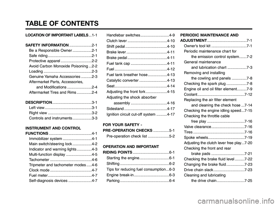
TABLE OF CONTENTS
LOCATION OF IMPORTANT LABELS...1-1
SAFETY INFORMATION.....................2-1
Be a Responsible Owner ..................2-1
Safe riding .........................................2-1
Protective apparel .............................2-2
Avoid Carbon Monoxide Poisoning ...2-2
Loading .............................................2-3
Genuine Yamaha Accessories ..........2-3
Aftermarket Parts, Accessories,
and Modifications .......................2-4
Aftermarket Tires and Rims ..............2-4
DESCRIPTION.....................................3-1
Left view ............................................3-1
Right view .........................................3-2
Controls and instruments ..................3-3
INSTRUMENT AND CONTROL
FUNCTIONS........................................4-1
Immobilizer system ...........................4-1
Main switch/steering lock ..................4-2
Indicator and warning lights ..............4-3
Multi-function display ........................4-5
Tachometer .......................................4-6
Tripmeter and tachometer modes .....4-6
Clock mode .......................................4-7
Fuel meter .........................................4-7
Self-diagnosis devices ......................4-7Handlebar switches ...........................4-9
Clutch lever .....................................4-10
Shift pedal .......................................4-10
Brake lever ......................................4-11
Brake pedal .....................................4-11
Fuel tank cap ..................................4-11
Fuel .................................................4-12
Fuel tank breather hose ..................4-13
Catalytic converter ..........................4-13
Seat .................................................4-14
Adjusting the front fork ....................4-15
Adjusting the shock absorber
assembly ..................................4-16
Sidestand ........................................4-17
Ignition circuit cut-off system ..........4-17
FOR YOUR SAFETY -
PRE-OPERATION CHECKS...............5-1
Pre-operation check list ....................5-2
OPERATION AND IMPORTANT
RIDING POINTS..................................6-1
Starting the engine............................6-1
Shifting ..............................................6-2
Tips for reducing fuel consumption ...6-3
Engine break-in .................................6-3
Parking ..............................................6-4PERIODIC MAINTENANCE AND
ADJUSTMENT.....................................7-1
Owner’s tool kit .................................7-1
Periodic maintenance chart for
the emission control system.......7-2
General maintenance
and lubrication chart ..................7-3
Removing and installing
the cowling and panels ..............7-8
Checking the spark plug ...................7-8
Engine oil and oil filter element.........7-9
Coolant ............................................7-12
Replacing the air filter element
and cleaning the check hose ...7-14
Checking the engine idling speed ...7-15
Checking the throttle cable
free play ...................................7-16
Valve clearance ...............................7-16
Tires ................................................7-16
Spoke wheels..................................7-19
Adjusting the clutch lever free play...7-20
Checking the front and rear
brake pads ...............................7-21
Checking the brake fluid level .........7-22
Changing the brake fluid .................7-23
Drive chain slack .............................7-23
Cleaning and lubricating
the drive chain ..........................7-25
XT660Z 01-03 ING-AUS:AUSTRALIA 11-05-2009 9:57 Pagina 6
Page 7 of 100
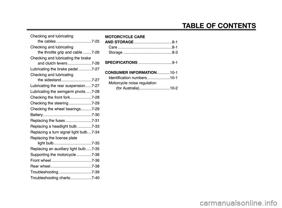
Checking and lubricating the cables .................................7-25
Checking and lubricating the throttle grip and cable ........7-26
Checking and lubricating the brake and clutch levers ......................7-26
Lubricating the brake pedal ............7-27
Checking and lubricating the sidestand ............................7-27
Lubricating the rear suspension......7-27
Lubricating the swingarm pivots .....7-28
Checking the front fork....................7-28
Checking the steering .....................7-29
Checking the wheel bearings..........7-29
Battery .............................................7-30
Replacing the fuses ........................7-31
Replacing a headlight bulb .............7-33
Replacing a turn signal light bulb....7-34
Replacing the license plate light bulb ...................................7-35
Replacing an auxiliary light bulb .....7-35
Supporting the motorcycle ..............7-36
Front wheel .....................................7-36
Rear wheel ......................................7-38
Troubleshooting ..............................7-39
Troubleshooting charts....................7-40 MOTORCYCLE CARE
AND STORAGE
...................................8-1
Care ..................................................8-1
Storage .............................................8-3
SPECIFICATIONS ...............................9-1
CONSUMER INFORMATION ............10-1
Identification numbers .....................10-1
Motorcycle noise regulation (for Australia) ............................10-2
TABLE OF CONTENTS
03 ingles -australia 26/2/10 10:45 Página 7
Page 11 of 100
1
2
3
4
5
6
7
8
9
10
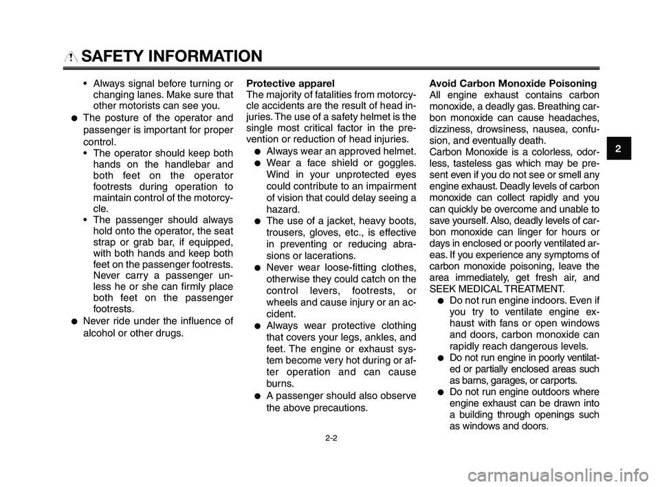
Always signal before turning or
changing lanes. Make sure that
other motorists can see you.
●The posture of the operator and
passenger is important for proper
control.
The operator should keep both
hands on the handlebar and
both feet on the operator
footrests during operation to
maintain control of the motorcy-
cle.
The passenger should always
hold onto the operator, the seat
strap or grab bar, if equipped,
with both hands and keep both
feet on the passenger footrests.
Never carry a passenger un-
less he or she can firmly place
both feet on the passenger
footrests.
●Never ride under the influence of
alcohol or other drugs.
2-2
Protective apparel
The majority of fatalities from motorcy-
cle accidents are the result of head in-
juries. The use of a safety helmet is the
single most critical factor in the pre-
vention or reduction of head injuries.
●Always wear an approved helmet.
●Wear a face shield or goggles.
Wind in your unprotected eyes
could contribute to an impairment
of vision that could delay seeing a
hazard.
●The use of a jacket, heavy boots,
trousers, gloves, etc., is effective
in preventing or reducing abra-
sions or lacerations.
●Never wear loose-fitting clothes,
otherwise they could catch on the
control levers, footrests, or
wheels and cause injury or an ac-
cident.
●Always wear protective clothing
that covers your legs, ankles, and
feet. The engine or exhaust sys-
tem become very hot during or af-
ter operation and can cause
burns.
●A passenger should also observe
the above precautions.Avoid Carbon Monoxide Poisoning
All engine exhaust contains carbon
monoxide, a deadly gas. Breathing car-
bon monoxide can cause headaches,
dizziness, drowsiness, nausea, confu-
sion, and eventually death.
Carbon Monoxide is a colorless, odor-
less, tasteless gas which may be pre-
sent even if you do not see or smell any
engine exhaust. Deadly levels of carbon
monoxide can collect rapidly and you
can quickly be overcome and unable to
save yourself. Also, deadly levels of car-
bon monoxide can linger for hours or
days in enclosed or poorly ventilated ar-
eas. If you experience any symptoms of
carbon monoxide poisoning, leave the
area immediately, get fresh air, and
SEEK MEDICAL TREATMENT.
●Do not run engine indoors. Even if
you try to ventilate engine ex-
haust with fans or open windows
and doors, carbon monoxide can
rapidly reach dangerous levels.
●Do not run engine in poorly ventilat-
ed or partially enclosed areas such
as barns, garages, or carports.
●Do not run engine outdoors where
engine exhaust can be drawn into
a building through openings such
as windows and doors.
SAFETY INFORMATION
XT660Z 01-03 ING-AUS:AUSTRALIA 11-05-2009 9:57 Pagina 11
Page 37 of 100
1
2
3
4
5
6
7
8
9
10
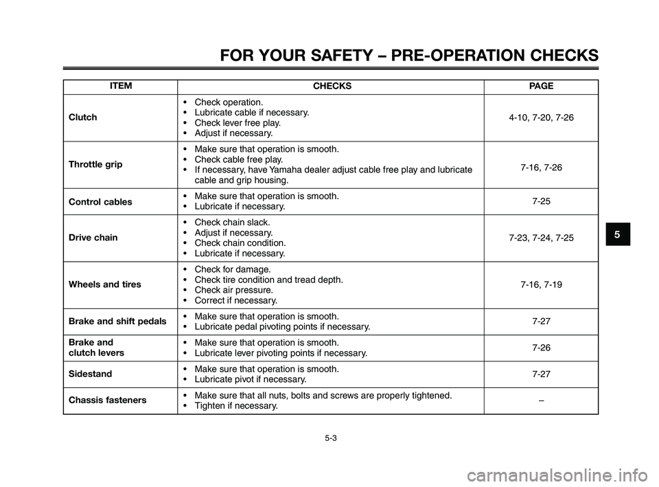
FOR YOUR SAFETY – PRE-OPERATION CHECKS
5-3
ITEM
Clutch
Throttle grip
Control cables
Drive chain
Wheels and tires
Brake and shift pedals
Brake and
clutch levers
Sidestand
Chassis fastenersCHECKS
Check operation.
Lubricate cable if necessary.
Check lever free play.
Adjust if necessary.
Make sure that operation is smooth.
Check cable free play.
If necessary, have Yamaha dealer adjust cable free play and lubricate
cable and grip housing.
Make sure that operation is smooth.
Lubricate if necessary.
Check chain slack.
Adjust if necessary.
Check chain condition.
Lubricate if necessary.
Check for damage.
Check tire condition and tread depth.
Check air pressure.
Correct if necessary.
Make sure that operation is smooth.
Lubricate pedal pivoting points if necessary.
Make sure that operation is smooth.
Lubricate lever pivoting points if necessary.
Make sure that operation is smooth.
Lubricate pivot if necessary.
Make sure that all nuts, bolts and screws are properly tightened.
Tighten if necessary.PAGE
4-10, 7-20, 7-26
7-16, 7-26
7-25
7-23, 7-24, 7-25
7-16, 7-19
7-27
7-26
7-27
–
XT660Z 05-07 ING-AUS:MY03 04-06 ING 11-05-2009 10:09 Pagina 3
Page 45 of 100
1
2
3
4
5
6
7
8
9
10
PERIODIC MAINTENANCE AND ADJUSTMENT
7-3
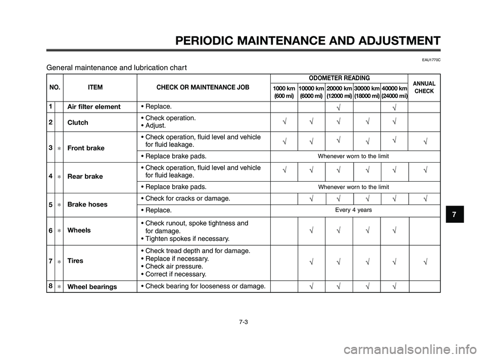
NO. ITEM CHECK OR MAINTENANCE JOB
ODOMETER READING
1000 km 10000 km 20000 km 30000 km 40000 km(600 mi) (6000 mi) (12000 mi) (18000 mi) (24000 mi)
ANNUAL
CHECK
√√
√√√ √√
√√√
√√
√
√√√ √√ √
√√ √√ √
√√ √√
√√ √√ √
√√ √√1
2
3
✻
4✻
5✻
6✻
7✻
8✻
Replace.
Check operation.
Adjust.
Check operation, fluid level and vehicle
for fluid leakage.
Replace brake pads.
Check operation, fluid level and vehicle
for fluid leakage.
Replace brake pads.
Check for cracks or damage.
Replace.
Check runout, spoke tightness and
for damage.
Tighten spokes if necessary.
Check tread depth and for damage.
Replace if necessary.
Check air pressure.
Correct if necessary.
Check bearing for looseness or damage. Air filter element
Clutch
Front brake
Rear brake
Brake hoses
Wheels
Tires
Wheel bearings
EAU1770C
General maintenance and lubrication chart
Whenever worn to the limit
Whenever worn to the limit
Every 4 years
XT660Z 05-07 ING-AUS:MY03 04-06 ING 11-05-2009 10:09 Pagina 7-3
Page 61 of 100
1
2
3
4
5
6
7
8
9
10
PERIODIC MAINTENANCE AND ADJUSTMENT
7-19
EAU21940
Spoke wheels
To maximize the performance, durabil-
ity, and safe operation of your motor-
cycle, note the following points regard-
ing the specified wheels.
●The wheel rims should be
checked for cracks, bends or
warpage, and the spokes for
looseness or damage before
each ride. If any damage is found,
have a Yamaha dealer replace the
wheel. Do not attempt even the
smallest repair to the wheel. A de-
formed or cracked wheel must be
replaced.●The wheel should be balanced
whenever either the tire or wheel
has been changed or replaced.
An unbalanced wheel can result
in poor performance, adverse
handling characteristics, and a
shortened tire life.
●Ride at moderate speeds after
changing a tire since the tire sur-
face must first be "broken in" for it
to develop its optimal characteris-
tics.
XT660Z 05-07 ING-AUS:MY03 04-06 ING 11-05-2009 10:09 Pagina 7-19
Page 65 of 100
1
2
3
4
5
6
7
8
9
10
PERIODIC MAINTENANCE AND ADJUSTMENT
7-23
EAU22731
Changing the brake fluid
Have a Yamaha dealer change the
brake fluid at the intervals specified in
the TIP after the periodic maintenance
and lubrication chart. In addition, have
the oil seals of the master cylinders
and calipers as well as the brake
hoses replaced at the intervals listed
below or whenever they are damaged
or leaking.
●Oil seals: Replace every two
years.
●Brake hoses: Replace every four
years.
EAU22760
Drive chain slack
The drive chain slack should be
checked before each ride and adjusted
if necessary.
EAU22783
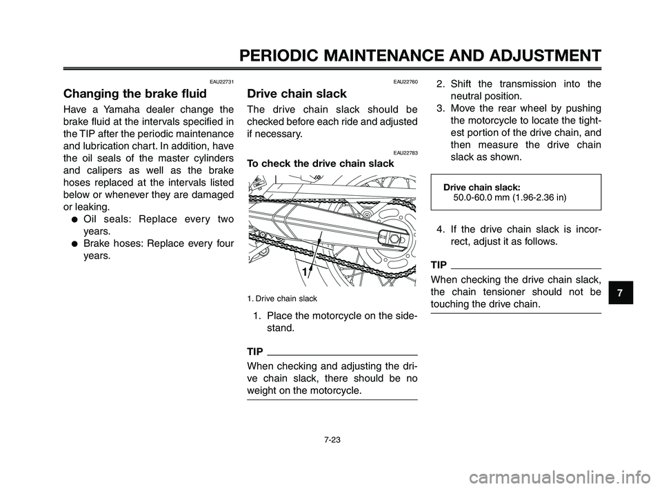
To check the drive chain slack
1. Drive chain slack
1. Place the motorcycle on the side-
stand.
TIP
When checking and adjusting the dri-
ve chain slack, there should be no
weight on the motorcycle.
2. Shift the transmission into the
neutral position.
3. Move the rear wheel by pushing
the motorcycle to locate the tight-
est portion of the drive chain, and
then measure the drive chain
slack as shown.
4. If the drive chain slack is incor-
rect, adjust it as follows.
TIP
When checking the drive chain slack,
the chain tensioner should not be
touching the drive chain.
Drive chain slack:
50.0-60.0 mm (1.96-2.36 in)
XT660Z 05-07 ING-AUS:MY03 04-06 ING 11-05-2009 10:10 Pagina 7-23
Page 66 of 100
PERIODIC MAINTENANCE AND ADJUSTMENT
7-24
1
2
3
4
5
6
7
8
9
10
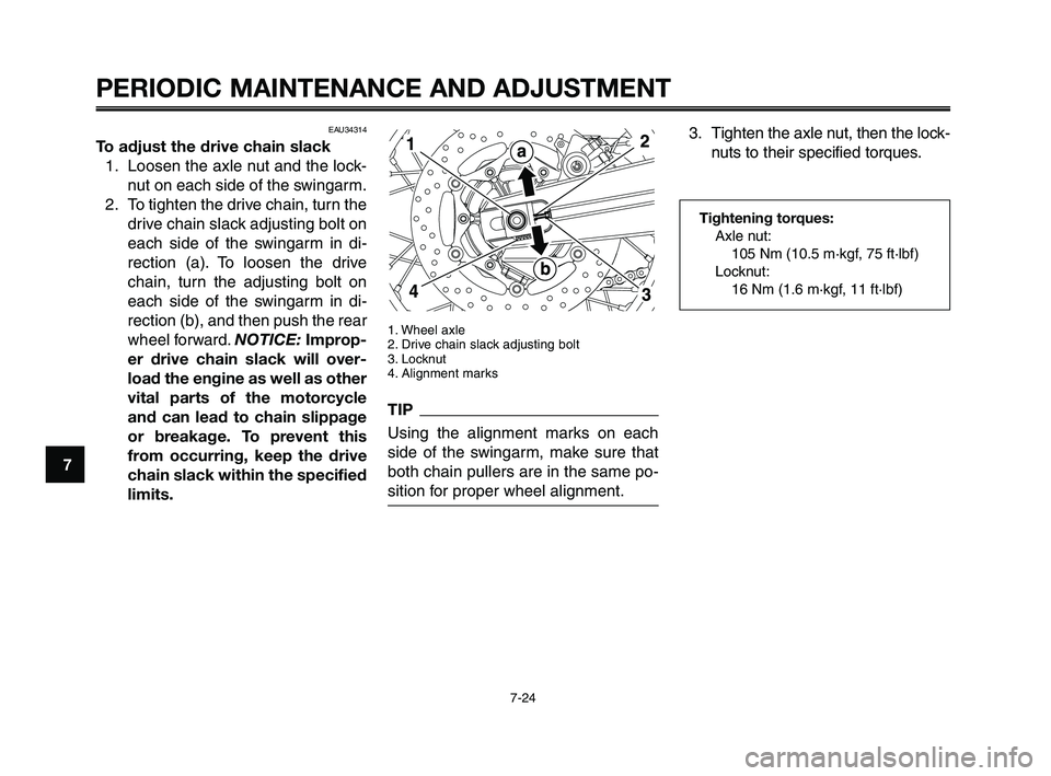
1. Wheel axle
2. Drive chain slack adjusting bolt
3. Locknut
4. Alignment marks
TIP
Using the alignment marks on each
side of the swingarm, make sure that
both chain pullers are in the same po-
sition for proper wheel alignment.
3. Tighten the axle nut, then the lock-
nuts to their specified torques.
Tightening torques:
Axle nut:
105 Nm (10.5 m·kgf, 75 ft·lbf)
Locknut:
16 Nm (1.6 m·kgf, 11 ft·lbf)
EAU34314
To adjust the drive chain slack
1. Loosen the axle nut and the lock-
nut on each side of the swingarm.
2. To tighten the drive chain, turn the
drive chain slack adjusting bolt on
each side of the swingarm in di-
rection (a). To loosen the drive
chain, turn the adjusting bolt on
each side of the swingarm in di-
rection (b), and then push the rear
wheel forward. NOTICE: Improp-
er drive chain slack will over-
load the engine as well as other
vital parts of the motorcycle
and can lead to chain slippage
or breakage. To prevent this
from occurring, keep the drive
chain slack within the specified
limits.
XT660Z 05-07 ING-AUS:MY03 04-06 ING 11-05-2009 10:10 Pagina 7-24
Page 71 of 100
1
2
3
4
5
6
7
8
9
10
PERIODIC MAINTENANCE AND ADJUSTMENT
7-29
EAU23283
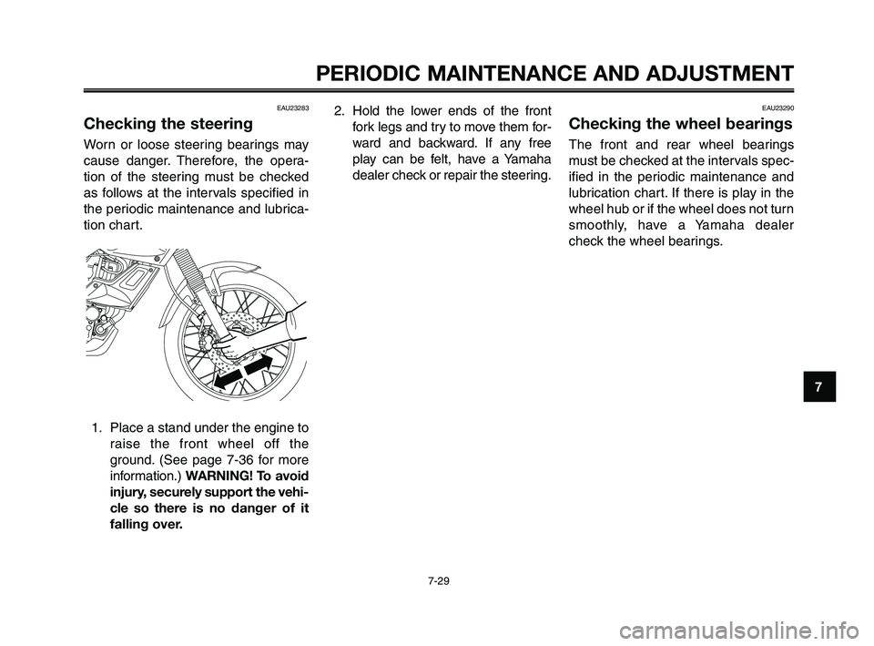
Checking the steering
Worn or loose steering bearings may
cause danger. Therefore, the opera-
tion of the steering must be checked
as follows at the intervals specified in
the periodic maintenance and lubrica-
tion chart.
1. Place a stand under the engine to
raise the front wheel off the
ground. (See page 7-36 for more
information.) WARNING! To avoid
injury, securely support the vehi-
cle so there is no danger of it
falling over.
2. Hold the lower ends of the front
fork legs and try to move them for-
ward and backward. If any free
play can be felt, have a Yamaha
dealer check or repair the steering.EAU23290
Checking the wheel bearings
The front and rear wheel bearings
must be checked at the intervals spec-
ified in the periodic maintenance and
lubrication chart. If there is play in the
wheel hub or if the wheel does not turn
smoothly, have a Yamaha dealer
check the wheel bearings.
XT660Z 05-07 ING-AUS:MY03 04-06 ING 11-05-2009 10:10 Pagina 7-29
Page 78 of 100
PERIODIC MAINTENANCE AND ADJUSTMENT
7-36
1
2
3
4
5
6
7
8
9
10
To service the rear wheel
Raise the rear wheel off the ground by
using a motorcycle stand or, if a mo-
torcycle stand is not available, by plac-
ing a jack either under each side of the
frame in front of the rear wheel or un-
der each side of the swingarm.EAU24360
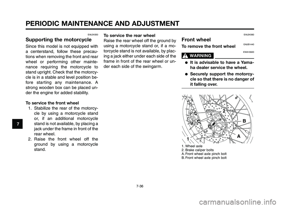
Front wheelEAUB1440To remove the front wheel
EWA10820
WARNING0
●It is advisable to have a Yama-
ha dealer service the wheel.
●Securely support the motorcy-
cle so that there is no danger of
it falling over.
1. Wheel axle
2. Brake caliper bolts
A. Front wheel axle pinch bolt
B. Front wheel axle pinch bolt
A
2
B
1
EAU24350
Supporting the motorcycle
Since this model is not equipped with
a centerstand, follow these precau-
tions when removing the front and rear
wheel or performing other mainte-
nance requiring the motorcycle to
stand upright. Check that the motorcy-
cle is in a stable and level position be-
fore starting any maintenance. A
strong wooden box can be placed un-
der the engine for added stability.
To service the front wheel
1. Stabilize the rear of the motorcy-
cle by using a motorcycle stand
or, if an additional motorcycle
stand is not available, by placing a
jack under the frame in front of the
rear wheel.
2. Raise the front wheel off the
ground by using a motorcycle
stand.
XT660Z 05-07 ING-AUS:MY03 04-06 ING 11-05-2009 10:10 Pagina 7-36