YAMAHA YZ426F 2000 Betriebsanleitungen (in German)
Manufacturer: YAMAHA, Model Year: 2000, Model line: YZ426F, Model: YAMAHA YZ426F 2000Pages: 608, PDF-Größe: 45.52 MB
Page 511 of 608
5 - 49
CHAS
DIRECTION
LENKKOPF
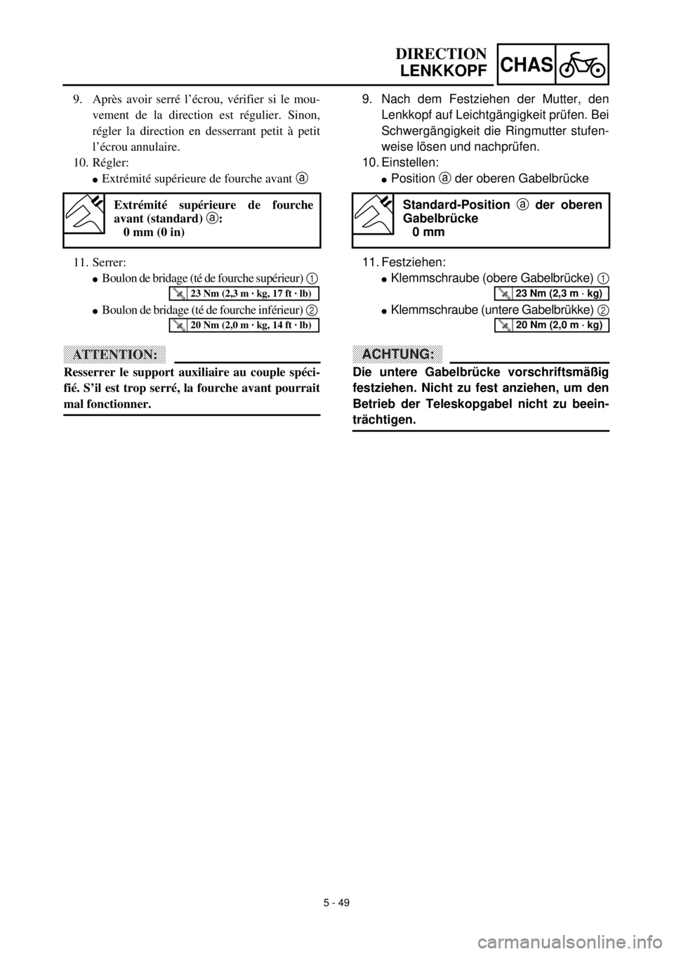
9. Nach dem Festziehen der Mutter, den
Lenkkopf auf Leichtgängigkeit prüfen. Bei
Schwergängigkeit die Ringmutter stufen-
weise lösen und nachprüfen.
10. Einstellen:
lPosition a der oberen Gabelbrücke
11. Festziehen:
lKlemmschraube (obere Gabelbrücke) 1
lKlemmschraube (untere Gabelbrükke) 2
ACHTUNG:
Die untere Gabelbrücke vorschriftsmäßig
festziehen. Nicht zu fest anziehen, um den
Betrieb der Teleskopgabel nicht zu beein-
trächtigen.
Standard-Position a der oberen
Gabelbrücke
0 mm
T R..23 Nm (2,3 m · kg)
T R..20 Nm (2,0 m · kg)
9. Après avoir serré l’écrou, vérifier si le mou-
vement de la direction est régulier. Sinon,
régler la direction en desserrant petit à petit
l’écrou annulaire.
10. Régler:
lExtrémité supérieure de fourche avant a
11. Serrer:
lBoulon de bridage (té de fourche supérieur) 1
lBoulon de bridage (té de fourche inférieur) 2
ATTENTION:
Resserrer le support auxiliaire au couple spéci-
fié. S’il est trop serré, la fourche avant pourrait
mal fonctionner.
Extrémité supérieure de fourche
avant (standard) a:
0 mm (0 in)
T R..23 Nm (2,3 m · kg, 17 ft · lb)
T R..20 Nm (2,0 m · kg, 14 ft · lb)
Page 512 of 608
5 - 51
CHASSWINGARM
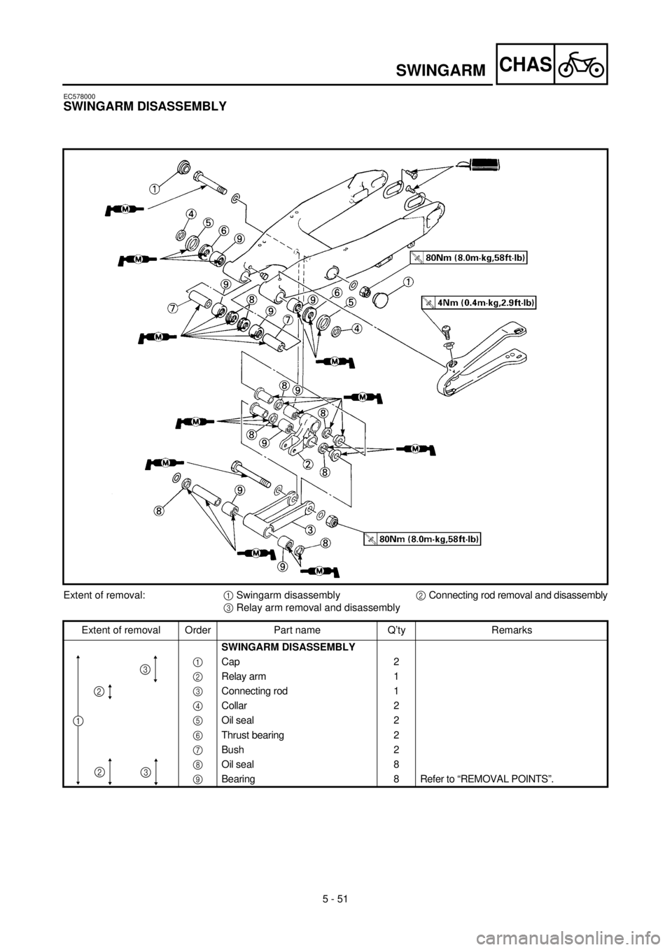
EC578000
SWINGARM DISASSEMBLY
Extent of removal:1 Swingarm disassembly2 Connecting rod removal and disassembly
3 Relay arm removal and disassembly
Extent of removal Order Part name Q’ty Remarks
SWINGARM DISASSEMBLY
1 Cap 2
2 Relay arm 1
3 Connecting rod 1
4 Collar 2
5 Oil seal 2
6 Thrust bearing 2
7 Bush 2
8 Oil seal 8
9 Bearing 8 Refer to “REMOVAL POINTS”.
1
2
2
3
3
Page 513 of 608
5 - 50
CHAS
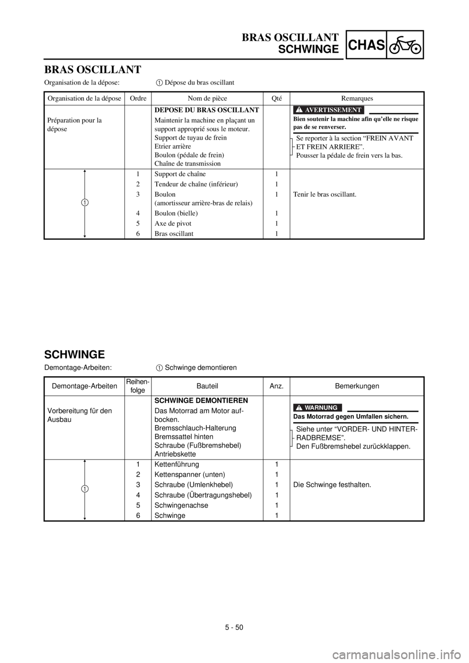
BRAS OSCILLANT
Organisation de la dépose:1 Dépose du bras oscillant
Organisation de la dépose Ordre Nom de pièce Qté Remarques
DEPOSE DU BRAS OSCILLANT
Se reporter à la section “FREIN AVANT
ET FREIN ARRIERE”.
Pousser la pédale de frein vers la bas. Préparation pour la
déposeMaintenir la machine en plaçant un
support approprié sous le moteur.
Support de tuyau de frein
Etrier arrière
Boulon (pédale de frein)
Chaîne de transmission
1 Support de chaîne 1
2 Tendeur de chaîne (inférieur) 1
3 Boulon
(amortisseur arrière-bras de relais)1 Tenir le bras oscillant.
4 Boulon (bielle) 1
5 Axe de pivot 1
6 Bras oscillant 1
AVERTISSEMENT
Bien soutenir la machine afin qu’elle ne risquepas de se renverser.
1
BRAS OSCILLANT
SCHWINGE
SCHWINGE
Demontage-Arbeiten:1 Schwinge demontieren
Demontage-ArbeitenReihen-
folgeBauteil Anz. Bemerkungen
SCHWINGE DEMONTIEREN
Siehe unter “VORDER- UND HINTER-
RADBREMSE”.
Den Fußbremshebel zurückklappen. Vorbereitung für den
AusbauDas Motorrad am Motor auf-
bocken.
Bremsschlauch-Halterung
Bremssattel hinten
Schraube (Fußbremshebel)
Antriebskette
1 Kettenführung 1
2 Kettenspanner (unten) 1
3 Schraube (Umlenkhebel) 1 Die Schwinge festhalten.
4 Schraube (Übertragungshebel) 1
5 Schwingenachse 1
6 Schwinge 1
WARNUNG
Das Motorrad gegen Umfallen sichern.
1
Page 514 of 608
5 - 50
CHASSWINGARM
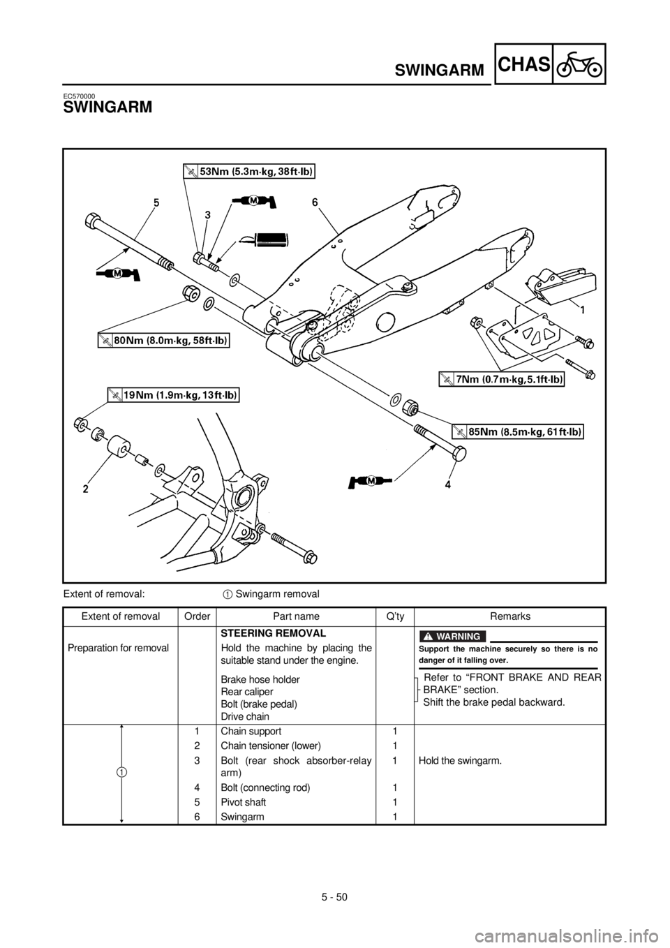
EC570000
SWINGARM
Extent of removal:1 Swingarm removal
Extent of removal Order Part name Q’ty Remarks
STEERING REMOVAL
Refer to “FRONT BRAKE AND REAR
BRAKE” section.
Shift the brake pedal backward. Preparation for removal Hold the machine by placing the
suitable stand under the engine.
Brake hose holder
Rear caliper
Bolt (brake pedal)
Drive chain
1 Chain support 1
2 Chain tensioner (lower) 1
3 Bolt (rear shock absorber-relay
arm)1 Hold the swingarm.
4 Bolt (connecting rod) 1
5 Pivot shaft 1
6 Swingarm 1
WARNING
Support the machine securely so there is nodanger of it falling over.
1
Page 515 of 608
5 - 51
CHAS
BRAS OSCILLANT
SCHWINGE
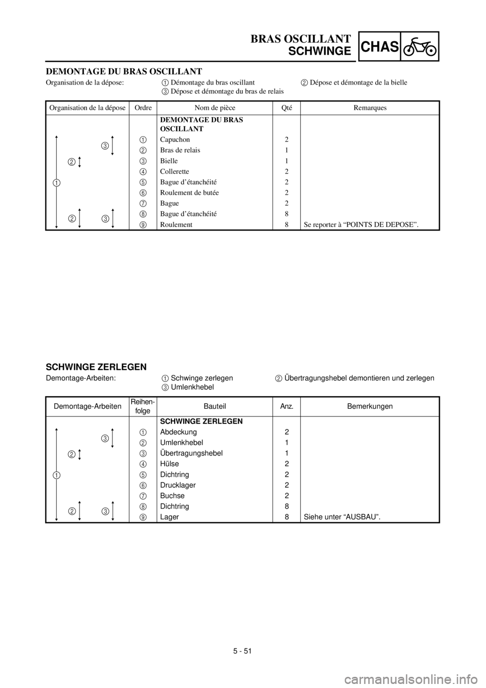
SCHWINGE ZERLEGEN
Demontage-Arbeiten:1 Schwinge zerlegen2 Übertragungshebel demontieren und zerlegen
3 Umlenkhebel
Demontage-ArbeitenReihen-
folgeBauteilAnz.Bemerkungen
SCHWINGE ZERLEGEN
1 Abdeckung 2
2 Umlenkhebel 1
3 Übertragungshebel 1
4 Hülse 2
5 Dichtring 2
6 Drucklager 2
7 Buchse 2
8 Dichtring 8
9Lager 8 Siehe unter “AUSBAU”.
1
2
2
3
3
DEMONTAGE DU BRAS OSCILLANT
Organisation de la dépose:1 Démontage du bras oscillant2 Dépose et démontage de la bielle
3 Dépose et démontage du bras de relais
Organisation de la dépose Ordre Nom de pièce Qté Remarques
DEMONTAGE DU BRAS
OSCILLANT
1 Capuchon 2
2 Bras de relais 1
3 Bielle 1
4 Collerette 2
5 Bague d’étanchéité 2
6 Roulement de butée 2
7 Bague 2
8 Bague d’étanchéité 8
9Roulement 8 Se reporter à “POINTS DE DEPOSE”.
1
2
2
3
3
Page 516 of 608
5 - 52
CHASSWINGARM
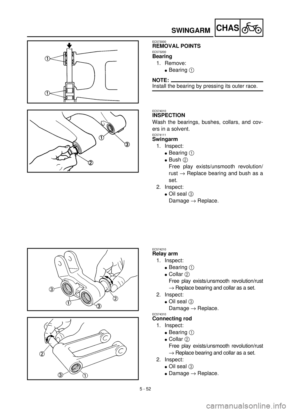
EC573000
REMOVAL POINTS
EC573200
Bearing
1. Remove:
lBearing 1
NOTE:
Install the bearing by pressing its outer race.
EC574010
INSPECTION
Wash the bearings, bushes, collars, and cov-
ers in a solvent.
EC574111
Swingarm
1. Inspect:
lBearing 1
lBush 2
Free play exists/unsmooth revolution/
rust ® Replace bearing and bush as a
set.
2. Inspect:
lOil seal 3
Damage ® Replace.
EC574210
Relay arm
1. Inspect:
lBearing 1
lCollar 2
Free play exists/unsmooth revolution/rust
® Replace bearing and collar as a set.
2. Inspect:
lOil seal 3
Damage ® Replace.
EC574310
Connecting rod
1. Inspect:
lBearing 1
lCollar 2
Free play exists/unsmooth revolution/rust
® Replace bearing and collar as a set.
2. Inspect:
lOil seal 3
lDamage ® Replace.
Page 517 of 608
5 - 52
CHAS
BRAS OSCILLANT
SCHWINGE
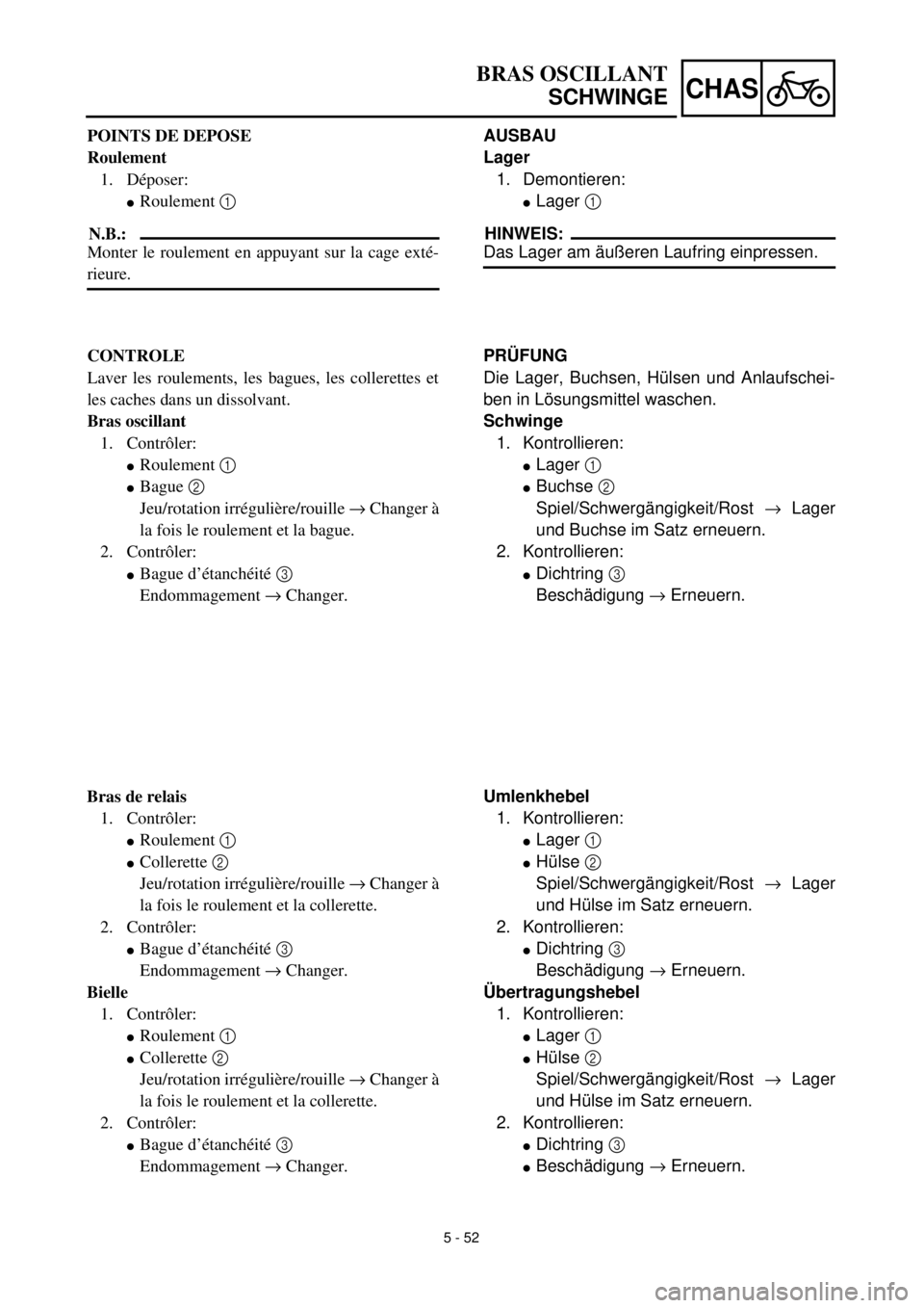
AUSBAU
Lager
1. Demontieren:
lLager 1
HINWEIS:
Das Lager am äußeren Laufring einpressen.
PRÜFUNG
Die Lager, Buchsen, Hülsen und Anlaufschei-
ben in Lösungsmittel waschen.
Schwinge
1. Kontrollieren:
lLager 1
lBuchse 2
Spiel/Schwergängigkeit/Rost ® Lager
und Buchse im Satz erneuern.
2. Kontrollieren:
lDichtring 3
Beschädigung ® Erneuern.
Umlenkhebel
1. Kontrollieren:
lLager 1
lHülse 2
Spiel/Schwergängigkeit/Rost ® Lager
und Hülse im Satz erneuern.
2. Kontrollieren:
lDichtring 3
Beschädigung ® Erneuern.
Übertragungshebel
1. Kontrollieren:
lLager 1
lHülse 2
Spiel/Schwergängigkeit/Rost ® Lager
und Hülse im Satz erneuern.
2. Kontrollieren:
lDichtring 3
lBeschädigung ® Erneuern. POINTS DE DEPOSE
Roulement
1. Déposer:
lRoulement 1
N.B.:
Monter le roulement en appuyant sur la cage exté-
rieure.
CONTROLE
Laver les roulements, les bagues, les collerettes et
les caches dans un dissolvant.
Bras oscillant
1. Contrôler:
lRoulement 1
lBague 2
Jeu/rotation irrégulière/rouille ® Changer à
la fois le roulement et la bague.
2. Contrôler:
lBague d’étanchéité 3
Endommagement ® Changer.
Bras de relais
1. Contrôler:
lRoulement 1
lCollerette 2
Jeu/rotation irrégulière/rouille ® Changer à
la fois le roulement et la collerette.
2. Contrôler:
lBague d’étanchéité 3
Endommagement ® Changer.
Bielle
1. Contrôler:
lRoulement 1
lCollerette 2
Jeu/rotation irrégulière/rouille ® Changer à
la fois le roulement et la collerette.
2. Contrôler:
lBague d’étanchéité 3
Endommagement ® Changer.
Page 518 of 608
5 - 53
CHASSWINGARM
EC575000
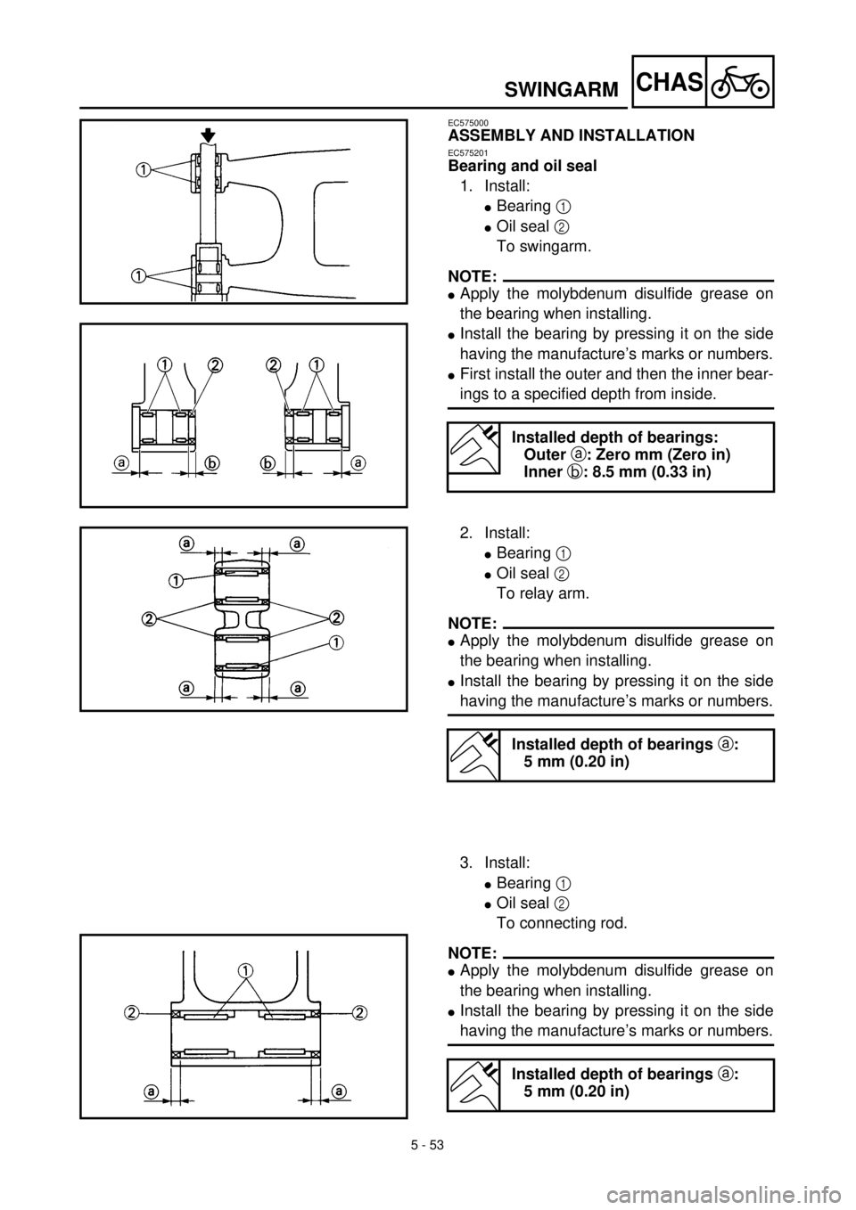
ASSEMBLY AND INSTALLATION
EC575201
Bearing and oil seal
1. Install:
lBearing 1
lOil seal 2
To swingarm.
NOTE:
lApply the molybdenum disulfide grease on
the bearing when installing.
lInstall the bearing by pressing it on the side
having the manufacture’s marks or numbers.
lFirst install the outer and then the inner bear-
ings to a specified depth from inside.
Installed depth of bearings:
Outer a: Zero mm (Zero in)
Inner b: 8.5 mm (0.33 in)
2. Install:
lBearing 1
lOil seal 2
To relay arm.
NOTE:
lApply the molybdenum disulfide grease on
the bearing when installing.
lInstall the bearing by pressing it on the side
having the manufacture’s marks or numbers.
3. Install:
lBearing 1
lOil seal 2
To connecting rod.
NOTE:
lApply the molybdenum disulfide grease on
the bearing when installing.
lInstall the bearing by pressing it on the side
having the manufacture’s marks or numbers.
Installed depth of bearings a:
5 mm (0.20 in)
Installed depth of bearings a:
5 mm (0.20 in)
Page 519 of 608
5 - 53
CHAS
BRAS OSCILLANT
SCHWINGE
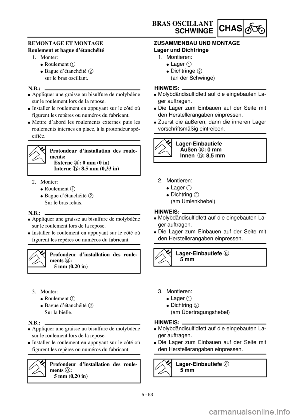
ZUSAMMENBAU UND MONTAGE
Lager und Dichtringe
1. Montieren:
lLager 1
lDichtringe 2
(an der Schwinge)
HINWEIS:
lMolybdändisulfidfett auf die eingebauten La-
ger auftragen.
lDie Lager zum Einbauen auf der Seite mit
den Herstellerangaben einpressen.
lZuerst die äußeren, dann die inneren Lager
vorschriftsmäßig eintreiben.
2. Montieren:
lLager 1
lDichtring 2
(am Umlenkhebel)
HINWEIS:
lMolybdändisulfidfett auf die eingebauten La-
ger auftragen.
lDie Lager zum Einbauen auf der Seite mit
den Herstellerangaben einpressen.
3. Montieren:
lLager 1
lDichtring 2
(am Übertragungshebel)
HINWEIS:
lMolybdändisulfidfett auf die eingebauten La-
ger auftragen.
lDie Lager zum Einbauen auf der Seite mit
den Herstellerangaben einpressen.
Lager-Einbautiefe
Außen a: 0 mm
Innen b: 8,5 mm
Lager-Einbautiefe a
5 mm
Lager-Einbautiefe a
5 mm
REMONTAGE ET MONTAGE
Roulement et bague d’étanchéité
1. Monter:
lRoulement 1
lBague d’étanchéité 2
sur le bras oscillant.
N.B.:
lAppliquer une graisse au bisulfure de molybdène
sur le roulement lors de la repose.
lInstaller le roulement en appuyant sur le côté où
figurent les repères ou numéros du fabricant.
lMettre d’abord les roulements externes puis les
roulements internes en place, à la protondeur spé-
cifiée.
2. Monter:
lRoulement 1
lBague d’étanchéité 2
Sur le bras relais.
N.B.:
lAppliquer une graisse au bisulfure de molybdène
sur le roulement lors de la repose.
lInstaller le roulement en appuyant sur le côté où
figurent les repères ou numéros du fabricant.
3. Monter:
lRoulement 1
lBague d’étanchéité 2
Sur la bielle.
N.B.:
lAppliquer une graisse au bisulfure de molybdène
sur le roulement lors de la repose.
lInstaller le roulement en appuyant sur le côté où
figurent les repères ou numéros du fabricant.
Protondeur d’installation des roule-
ments:
Externe a: 0 mm (0 in)
Interne b: 8,5 mm (0,33 in)
Profondeur d’installation des roule-
ments a:
5 mm (0,20 in)
Profondeur d’installation des roule-
ments a:
5 mm (0,20 in)
Page 520 of 608
5 - 54
CHASSWINGARM
EC5751A0
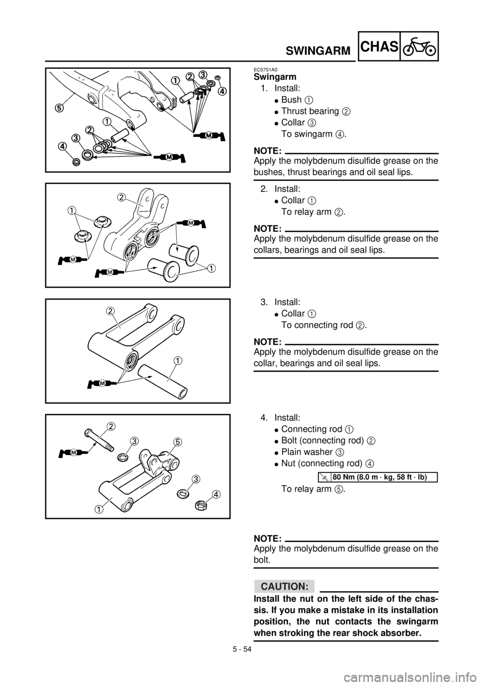
Swingarm
1. Install:
lBush 1
lThrust bearing 2
lCollar 3
To swingarm 4.
NOTE:
Apply the molybdenum disulfide grease on the
bushes, thrust bearings and oil seal lips.
2. Install:
lCollar 1
To relay arm 2.
NOTE:
Apply the molybdenum disulfide grease on the
collars, bearings and oil seal lips.
3. Install:
lCollar 1
To connecting rod 2.
NOTE:
Apply the molybdenum disulfide grease on the
collar, bearings and oil seal lips.
4. Install:
lConnecting rod 1
lBolt (connecting rod) 2
lPlain washer 3
lNut (connecting rod) 4
To relay arm 5.
T R..80 Nm (8.0 m · kg, 58 ft · lb)
NOTE:
Apply the molybdenum disulfide grease on the
bolt.
ACHTUNG:CAUTION:
Install the nut on the left side of the chas-
sis. If you make a mistake in its installation
position, the nut contacts the swingarm
when stroking the rear shock absorber.