YAMAHA YZ426F 2000 Betriebsanleitungen (in German)
Manufacturer: YAMAHA, Model Year: 2000, Model line: YZ426F, Model: YAMAHA YZ426F 2000Pages: 608, PDF-Größe: 45.52 MB
Page 481 of 608
5 - 34
CHAS
FOURCHE AVANT
TELESKOPGABEL
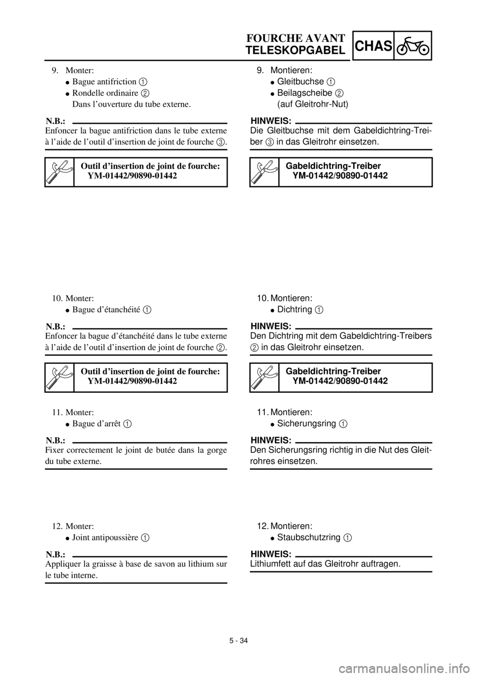
9. Montieren:
lGleitbuchse 1
lBeilagscheibe 2
(auf Gleitrohr-Nut)
HINWEIS:
Die Gleitbuchse mit dem Gabeldichtring-Trei-
ber 3 in das Gleitrohr einsetzen.
Gabeldichtring-Treiber
YM-01442/90890-01442
10. Montieren:
lDichtring 1
HINWEIS:
Den Dichtring mit dem Gabeldichtring-Treibers
2 in das Gleitrohr einsetzen.
Gabeldichtring-Treiber
YM-01442/90890-01442
11. Montieren:
lSicherungsring 1
HINWEIS:
Den Sicherungsring richtig in die Nut des Gleit-
rohres einsetzen.
12. Montieren:
lStaubschutzring 1
HINWEIS:
Lithiumfett auf das Gleitrohr auftragen. 9. Monter:
lBague antifriction 1
lRondelle ordinaire 2
Dans l’ouverture du tube externe.
N.B.:
Enfoncer la bague antifriction dans le tube externe
à l’aide de l’outil d’insertion de joint de fourche 3.
Outil d’insertion de joint de fourche:
YM-01442/90890-01442
10. Monter:
lBague d’étanchéité 1
N.B.:
Enfoncer la bague d’étanchéité dans le tube externe
à l’aide de l’outil d’insertion de joint de fourche 2.
Outil d’insertion de joint de fourche:
YM-01442/90890-01442
11. Monter:
lBague d’arrêt 1
N.B.:
Fixer correctement le joint de butée dans la gorge
du tube externe.
12. Monter:
lJoint antipoussière 1
N.B.:
Appliquer la graisse à base de savon au lithium sur
le tube interne.
Page 482 of 608
5 - 35
CHASFRONT FORK
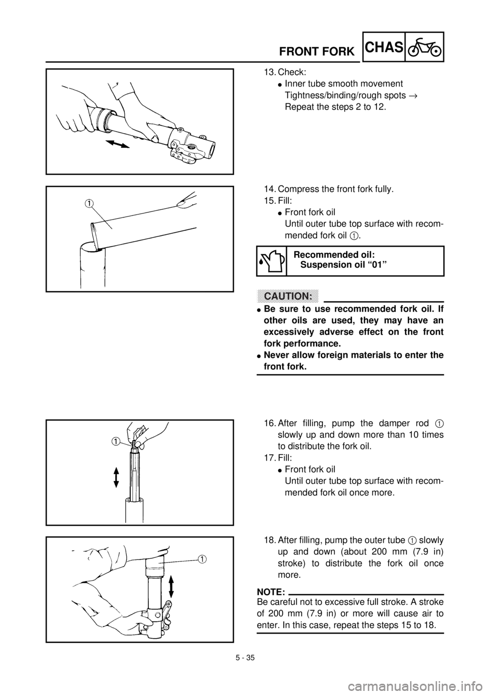
13. Check:
lInner tube smooth movement
Tightness/binding/rough spots ®
Repeat the steps 2 to 12.
14. Compress the front fork fully.
15. Fill:
lFront fork oil
Until outer tube top surface with recom-
mended fork oil 1.
ACHTUNG:CAUTION:
lBe sure to use recommended fork oil. If
other oils are used, they may have an
excessively adverse effect on the front
fork performance.
lNever allow foreign materials to enter the
front fork.
Recommended oil:
Suspension oil “01”
16. After filling, pump the damper rod 1
slowly up and down more than 10 times
to distribute the fork oil.
17. Fill:
lFront fork oil
Until outer tube top surface with recom-
mended fork oil once more.
18. After filling, pump the outer tube 1 slowly
up and down (about 200 mm (7.9 in)
stroke) to distribute the fork oil once
more.
NOTE:
Be careful not to excessive full stroke. A stroke
of 200 mm (7.9 in) or more will cause air to
enter. In this case, repeat the steps 15 to 18.
Page 483 of 608
5 - 35
CHAS
FOURCHE AVANT
TELESKOPGABEL
13. Kontrollieren:
lLeichtgängigkeit des Standrohres
Schwergängigkeit ® Die Schritte 2 bis
12 wiederholen. 13. Contrôler:lMouvement régulier du tube interne
Raideur/coincement/point dur ® Répéter
les étapes du 2 à 12.
14. Die Teleskopgabel ganz zusammendrük-
ken.
15. Befüllen:
lGleitrohr
bis zum Rand mit Öl 1 der empfohle-
nen Sorte
ACHTUNG:
lAusschließlich Öl der empfohlenen Sorte
verwenden, um die richtige Funktion der
Teleskopgabel zu gewährleisten.
lUNTER KEINEN UMSTÄNDEN Fremdkör-
per in die Teleskopgabel eindringen las-
sen.
Empfohlene Ölsorte
Gabelöl “01”
16. Nach dem Befüllen der Gabel muß das
Dämpferrohr 1 mehrmals (mindestens
10 Mal) ein- und ausgefedert werden, da-
mit sich das Gabelöl verteilt.
17. Befüllen:
lGleitrohr
bis zum Rand mit Öl der empfohlenen
Sorte.
18. Danach muß das Standrohr 1 langsam
um maximal 200 mm ein- und ausgefe-
dert werden, damit sich das Gabelöl ver-
teilt.
HINWEIS:
Wird das Standrohr mehr als 200 mm ein-
oder ausgefedert, tritt Luft ein. In diesem Fall
die Schritte 15 bis 18 wiederholen. 14. Comprimer la fourche avant complètement.
15. Remplir:
lHuile de fourche avant
Jusqu’au sommet du tube externe avec
l’huile de fourche recommandée 1.
ATTENTION:
lToujours utiliser l’huile de fourche recom-
mandée. Si d’autres huiles sont utilisées, elles
peuvent avoir un effet nuisible sur le rende-
ment de la fourche avant.
lNe jamais laisser de substance étrangère péné-
trer dans la fourche avant.
Huile recommandée:
Huile de suspension “01”
16. Après le remplissage, pomper lentement plus
de 10 fois vers le haut et le bas la tige d’amor-
tisseur 1 pour distribuer l’huile du fourche.
17. Remplir:
lHuile de fourche avant
Une nouvelle fois jusqu’au sommet du tube
externe avec l’huile de fourche recomman-
dée.
18. Une fois le remplissage de l’huile de fourche
terminé, pomper le tube externe 1 de haut en
bas (course de environ 200 mm (7,9 in)) pour
assurer une nouvelle fois la bonne répartition
de l’huile de fourche.
N.B.:
Faire attention à ne pas dépasser la pleine course.
Une course de 200 mm (7,9 in) ou plus fera entrer
de l’air. Dans ce cas, répéter les étapes 15 à 18.
Page 484 of 608
5 - 36
CHASFRONT FORK
19. Wait ten minutes until the air bubbles
have been removed from the front fork,
and the oil has dispense evenly in system
before setting recommended oil level.
NOTE:
Fill with the fork oil up to the top end of the
outer tube, or the fork oil will not spread over to
every part of the front forks, thus making it
impossible to obtain the correct level.
Be sure to fill with the fork oil up to the top of
the outer tube and bleed the front forks.
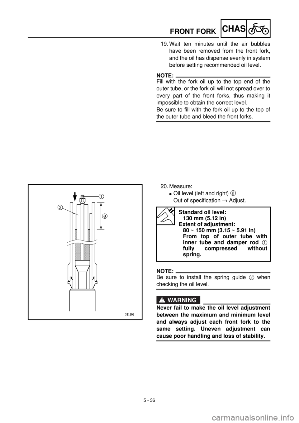
20. Measure:
lOil level (left and right) a
Out of specification ® Adjust.
NOTE:
Be sure to install the spring guide 2 when
checking the oil level.
WARNING
Never fail to make the oil level adjustment
between the maximum and minimum level
and always adjust each front fork to the
same setting. Uneven adjustment can
cause poor handling and loss of stability.
Standard oil level:
130 mm (5.12 in)
Extent of adjustment:
80 ~ 150 mm (3.15 ~ 5.91 in)
From top of outer tube with
inner tube and damper rod 1
fully compressed without
spring.
Page 485 of 608
5 - 36
CHAS
FOURCHE AVANT
TELESKOPGABEL
19. Zehn Minuten warten, bis etwaige Luft-
bläschen sich aufgelöst haben, bevor der
Gabelölstand gemessen wird.
HINWEIS:
Das Gleitrohr bis zum Rand mit Gabelöl befül-
len, anderenfalls verteilt sich das Öl nicht rich-
tig und kann der richtige Ölstand nicht erreicht
werden.
Sicherstellen, daß sich keine Luft in der Tele-
skopgabel befindet.
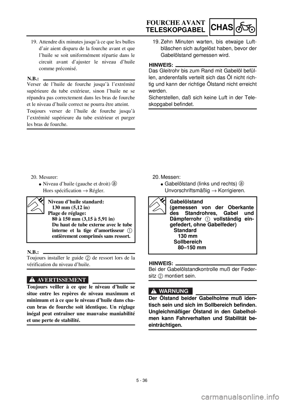
20. Messen:
lGabelölstand (links und rechts) a
Unvorschriftsmäßig ® Korrigieren.
HINWEIS:
Bei der Gabelölstandkontrolle muß der Feder-
sitz 2 montiert sein.
WARNUNG
Der Ölstand beider Gabelholme muß iden-
tisch sein und sich im Sollbereich befinden.
Ungleichmäßiger Ölstand in den Gabelhol-
men kann Fahrverhalten und Stabilität be-
einträchtigen.
Gabelölstand
(gemessen von der Oberkante
des Standrohres, Gabel und
Dämpferrohr 1 vollständig ein-
gefedert, ohne Gabelfeder)
Standard
130 mm
Sollbereich
80–150 mm
19. Attendre dix minutes jusqu’à ce que les bulles
d’air aient disparu de la fourche avant et que
l’huile se soit uniformément répartie dans le
circuit avant d’ajuster le niveau d’huile
comme préconisé.
N.B.:
Verser de l’huile de fourche jusqu’à l’extrémité
supérieure du tube extérieur, sinon l’huile ne se
répandra pas correctement dans les bras de fourche
et le niveau d’huile correct ne pourra être atteint.
Toujours verser de l’huile de fourche jusqu’à
l’extrémité supérieure du tube extérieur et purger
les bras de fourche.
20. Mesurer:
lNiveau d’huile (gauche et droit) a
Hors spécification ® Régler.
N.B.:
Toujours installer le guide 2 de ressort lors de la
vérification du niveau d’huile.
AVERTISSEMENT
Toujours veiller à ce que le niveau d’huile se
situe entre les repères de niveau maximum et
minimum et à ce que le niveau d’huile dans cha-
cun bras de fourche soit identique. Un réglage
inégal peut entraîner une mauvaise maniabilité
et une perte de stabilité.
Niveau d’huile standard:
130 mm (5,12 in)
Plage de réglage:
80 à 150 mm (3,15 à 5,91 in)
Du haut de tube externe avec le tube
interne et la tige d’amortisseur 1
entièrement comprimés sans ressort.
Page 486 of 608
5 - 37
CHASFRONT FORK
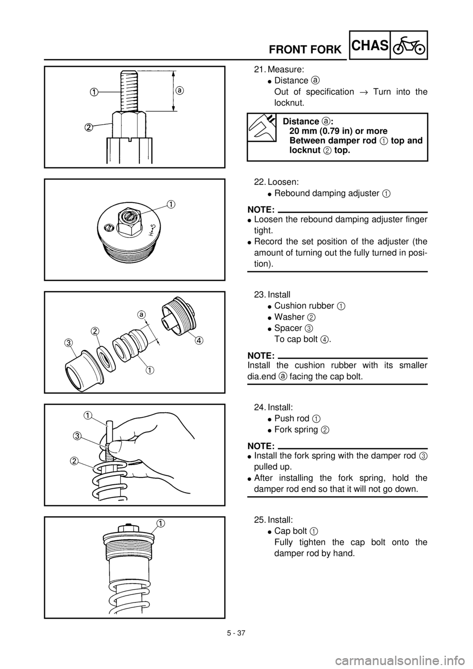
21. Measure:
lDistance a
Out of specification ® Turn into the
locknut.
Distance a:
20 mm (0.79 in) or more
Between damper rod 1 top and
locknut 2 top.
22. Loosen:
lRebound damping adjuster 1
NOTE:
lLoosen the rebound damping adjuster finger
tight.
lRecord the set position of the adjuster (the
amount of turning out the fully turned in posi-
tion).
23. Install
lCushion rubber 1
lWasher 2
lSpacer 3
To cap bolt 4.
NOTE:
Install the cushion rubber with its smaller
dia.end a facing the cap bolt.
24. Install:
lPush rod 1
lFork spring 2
NOTE:
lInstall the fork spring with the damper rod 3
pulled up.
lAfter installing the fork spring, hold the
damper rod end so that it will not go down.
25. Install:
lCap bolt 1
Fully tighten the cap bolt onto the
damper rod by hand.
Page 487 of 608
5 - 37
CHAS
FOURCHE AVANT
TELESKOPGABEL
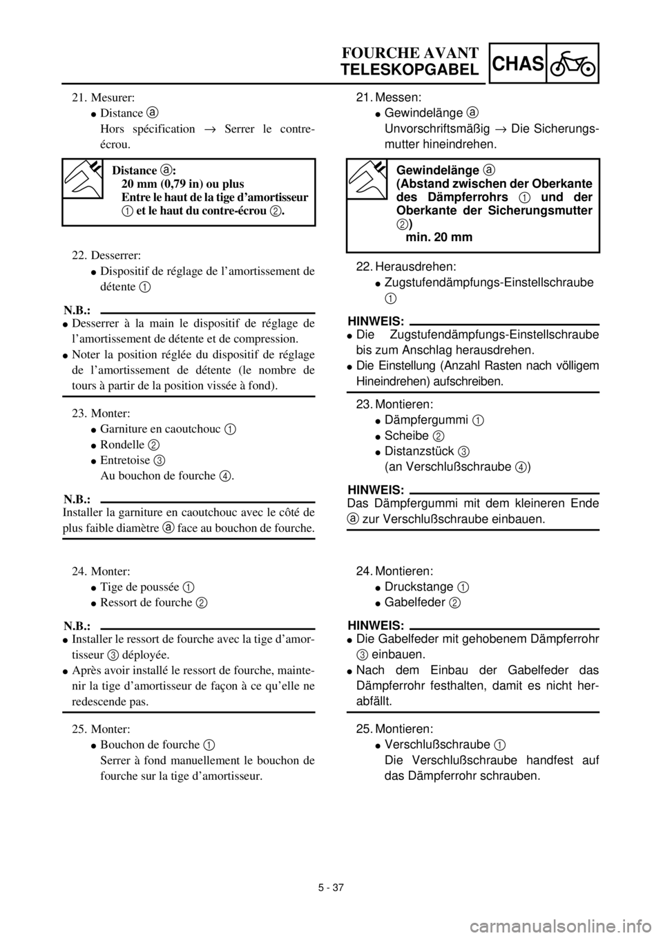
21. Messen:
lGewindelänge a
Unvorschriftsmäßig ® Die Sicherungs-
mutter hineindrehen.
22. Herausdrehen:
lZugstufendämpfungs-Einstellschraube
1
HINWEIS:
lDie Zugstufendämpfungs-Einstellschraube
bis zum Anschlag herausdrehen.
lDie Einstellung (Anzahl Rasten nach völligem
Hineindrehen) aufschreiben.
23. Montieren:
lDämpfergummi 1
lScheibe 2
lDistanzstück 3
(an Verschlußschraube 4)
HINWEIS:
Das Dämpfergummi mit dem kleineren Ende
a zur Verschlußschraube einbauen.
Gewindelänge a
(Abstand zwischen der Oberkante
des Dämpferrohrs 1 und der
Oberkante der Sicherungsmutter
2)
min. 20 mm
21. Mesurer:
lDistance a
Hors spécification ® Serrer le contre-
écrou.
Distance a:
20 mm (0,79 in) ou plus
Entre le haut de la tige d’amortisseur
1 et le haut du contre-écrou 2.
24. Montieren:
lDruckstange 1
lGabelfeder 2
HINWEIS:
lDie Gabelfeder mit gehobenem Dämpferrohr
3 einbauen.
lNach dem Einbau der Gabelfeder das
Dämpferrohr festhalten, damit es nicht her-
abfällt.
25. Montieren:
lVerschlußschraube 1
Die Verschlußschraube handfest auf
das Dämpferrohr schrauben. 22. Desserrer:
lDispositif de réglage de l’amortissement de
détente 1
N.B.:
lDesserrer à la main le dispositif de réglage de
l’amortissement de détente et de compression.
lNoter la position réglée du dispositif de réglage
de l’amortissement de détente (le nombre de
tours à partir de la position vissée à fond).
23. Monter:
lGarniture en caoutchouc 1
lRondelle 2
lEntretoise 3
Au bouchon de fourche 4.
N.B.:
Installer la garniture en caoutchouc avec le côté de
plus faible diamètre a face au bouchon de fourche.
24. Monter:
lTige de poussée 1
lRessort de fourche 2
N.B.:
lInstaller le ressort de fourche avec la tige d’amor-
tisseur 3 déployée.
lAprès avoir installé le ressort de fourche, mainte-
nir la tige d’amortisseur de façon à ce qu’elle ne
redescende pas.
25. Monter:
lBouchon de fourche 1
Serrer à fond manuellement le bouchon de
fourche sur la tige d’amortisseur.
Page 488 of 608
5 - 38
CHASFRONT FORK
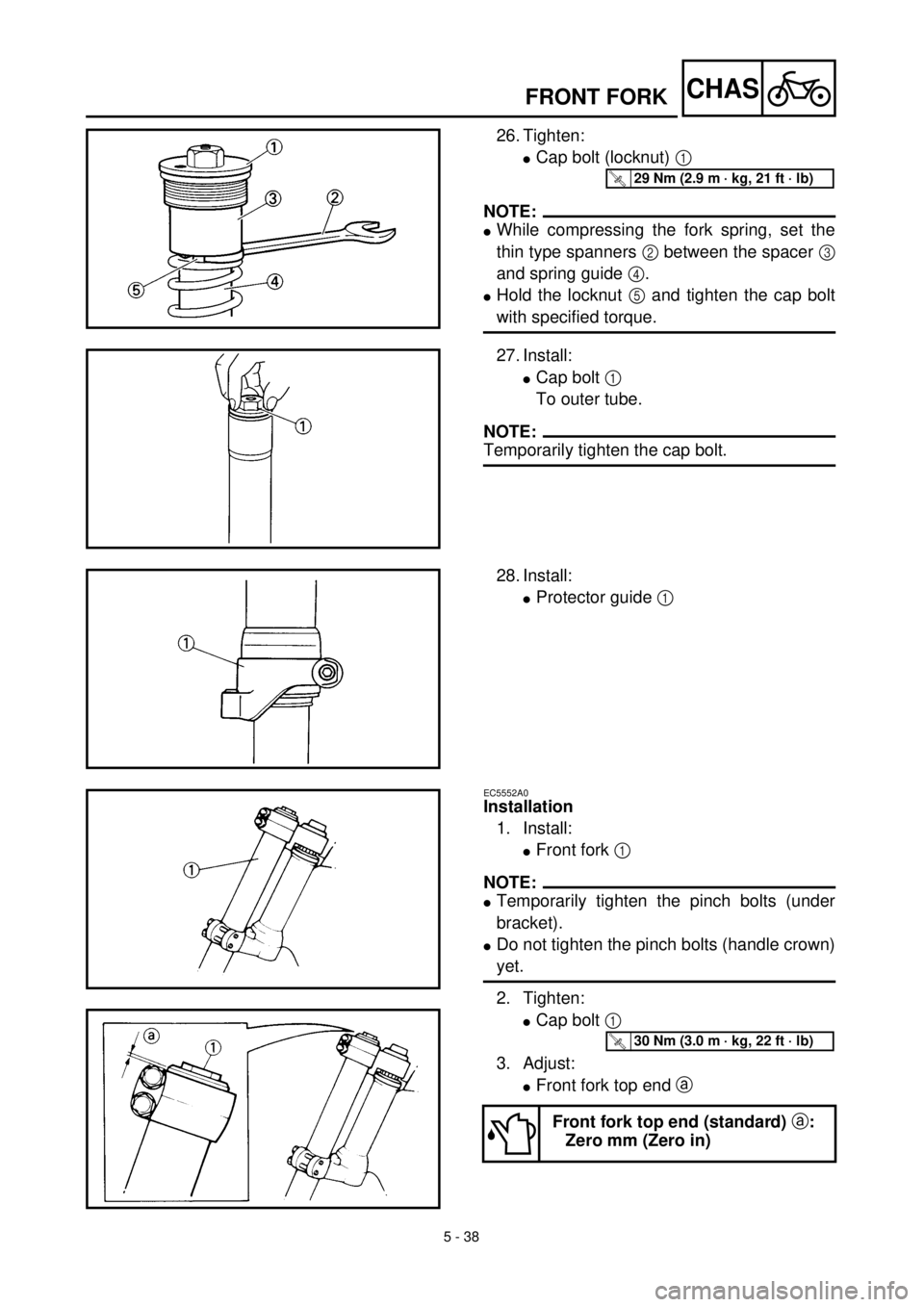
26. Tighten:
lCap bolt (locknut) 1
NOTE:
lWhile compressing the fork spring, set the
thin type spanners 2 between the spacer 3
and spring guide 4.
lHold the locknut 5 and tighten the cap bolt
with specified torque.
T R..29 Nm (2.9 m · kg, 21 ft · lb)
27. Install:
lCap bolt 1
To outer tube.
NOTE:
Temporarily tighten the cap bolt.
28. Install:
lProtector guide 1
EC5552A0
Installation
1. Install:
lFront fork 1
NOTE:
lTemporarily tighten the pinch bolts (under
bracket).
lDo not tighten the pinch bolts (handle crown)
yet.
2. Tighten:
lCap bolt 1
3. Adjust:
lFront fork top end a
Front fork top end (standard) a:
Zero mm (Zero in)
T R..30 Nm (3.0 m · kg, 22 ft · lb)
Page 489 of 608
5 - 38
CHAS
FOURCHE AVANT
TELESKOPGABEL
26. Festziehen:
lVerschlußschraube 1
HINWEIS:
lDie Gabelfeder komprimieren und dabei ei-
nen flachen Schlüssel 2 zwischen dem Di-
stanzstück 3 und dem Federsitz 4 anset-
zen.
lDie Sicherungsmutter 5 gegenhalten und
die Verschlußschraube vorschriftsmäßig
festziehen.
27. Montieren:
lVerschlußschraube 1
(am Gleitrohr)
HINWEIS:
Die Verschlußschraube provisorisch festzie-
hen.
T R..29 Nm (2,9 m · kg)
28. Montieren:
lProtektor-Führung 1
Einbau
1. Montieren:
lTeleskopgabel 1
HINWEIS:
lDie Klemmschrauben der unteren Gabel-
brücke provisorisch festziehen.
lDie Klemmschrauben der oberen Gabelbrük-
ke noch nicht festziehen.
2. Festziehen:
lVerschlußschraube 1
3. Einstellen:
lPosition a der oberen Gabelbrücke
Standard-Position a der oberen
Gabelbrücke
0 mm
T R..30 Nm (3,0 m · kg)
26. Serrer:
lBouchon de fourche (contre-écrou) 1
N.B.:
lTout en comprimant le ressort de fourche, placer
la clé à ergots fine 2 entre l’entretoise 3 et le
guide de ressort 4.
lMaintenir le contre-écrou 5 et serrer le bouchon
de fourche au couple de serrage spécifié.
27. Monter:
lBouchon de fourche 1
Sur le tube externe.
N.B.:
Serrer le bouchon de fourche de quelques tours.
T R..29 Nm (2,9 m · kg, 21 ft · lb)
28. Monter:
lGuide de protection 1
Montage
1. Monter:
lFourche avant 1
N.B.:
lSerrer provisoirement le boulon de bridage (té de
fourche inférieur).
lNe pas encore serrer le boulon de bridage (té de
fourche supérieur).
2. Serrer:
lBouchon de fourche 1
3. Régler:
lSommet de fourche avant a
Sommet de fourche avant (standard)
a:
0 mm (0 in)
T R..30 Nm (3,0 m · kg, 22 ft · lb)
Page 490 of 608
5 - 39
CHASFRONT FORK
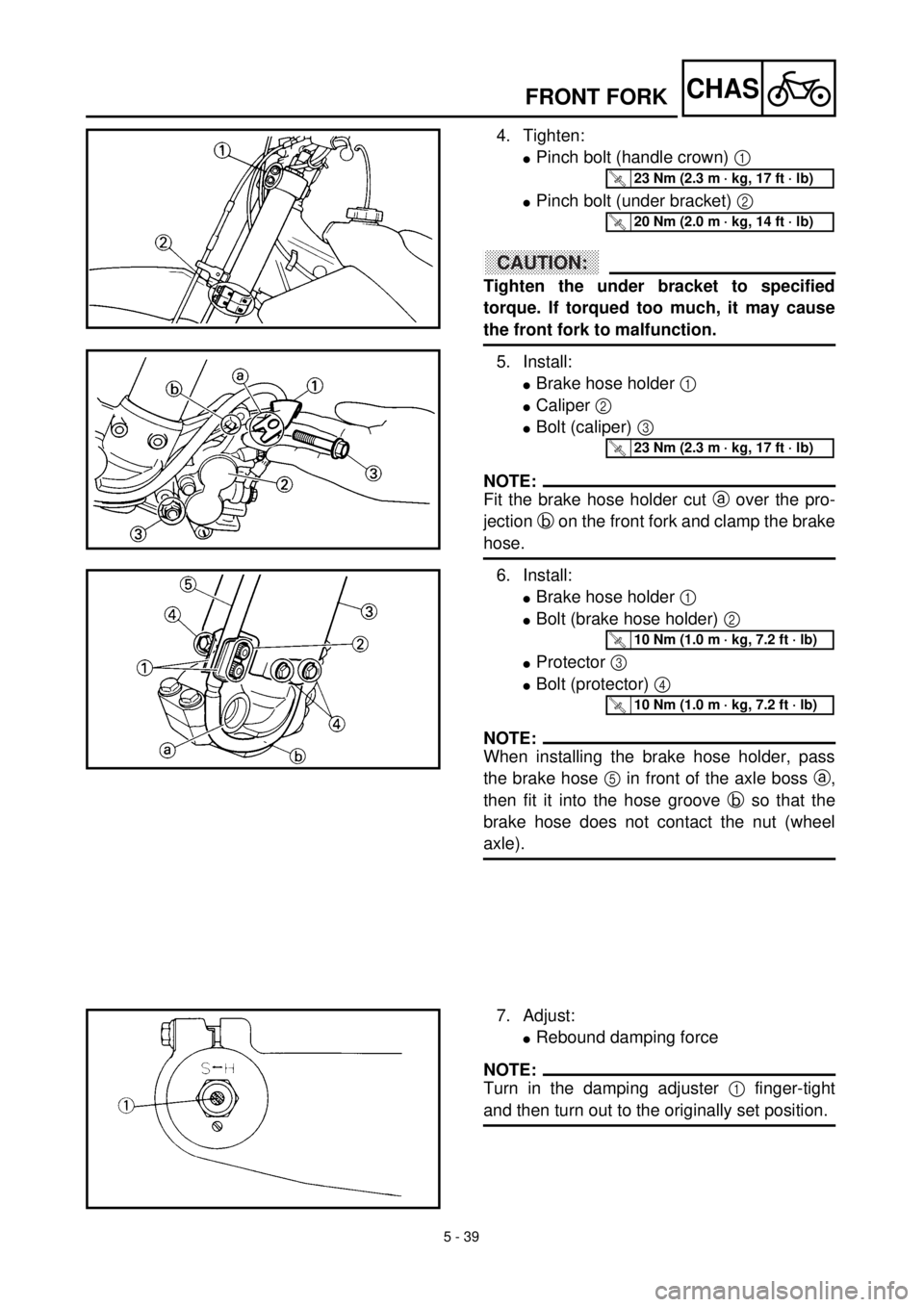
4. Tighten:
lPinch bolt (handle crown) 1
lPinch bolt (under bracket) 2
ACHTUNG:CAUTION:
Tighten the under bracket to specified
torque. If torqued too much, it may cause
the front fork to malfunction.
5. Install:
lBrake hose holder 1
lCaliper 2
lBolt (caliper) 3
NOTE:
Fit the brake hose holder cut a over the pro-
jection b on the front fork and clamp the brake
hose.
6. Install:
lBrake hose holder 1
lBolt (brake hose holder) 2
lProtector 3
lBolt (protector) 4
NOTE:
When installing the brake hose holder, pass
the brake hose 5 in front of the axle boss a,
then fit it into the hose groove b so that the
brake hose does not contact the nut (wheel
axle).
T R..23 Nm (2.3 m · kg, 17 ft · lb)
T R..20 Nm (2.0 m · kg, 14 ft · lb)
T R..23 Nm (2.3 m · kg, 17 ft · lb)
T R..10 Nm (1.0 m · kg, 7.2 ft · lb)
T R..10 Nm (1.0 m · kg, 7.2 ft · lb)
7. Adjust:
lRebound damping force
NOTE:
Turn in the damping adjuster 1 finger-tight
and then turn out to the originally set position.