ACURA NSX 1991 Service Repair Manual
Manufacturer: ACURA, Model Year: 1991,
Model line: NSX,
Model: ACURA NSX 1991
Pages: 1640, PDF Size: 60.48 MB
ACURA NSX 1991 Service Repair Manual
NSX 1991
ACURA
ACURA
https://www.carmanualsonline.info/img/32/56988/w960_56988-0.png
ACURA NSX 1991 Service Repair Manual
Trending: service indicator, transmission, roof, jacking, transmission oil, drain bolt, change time
Page 781 of 1640
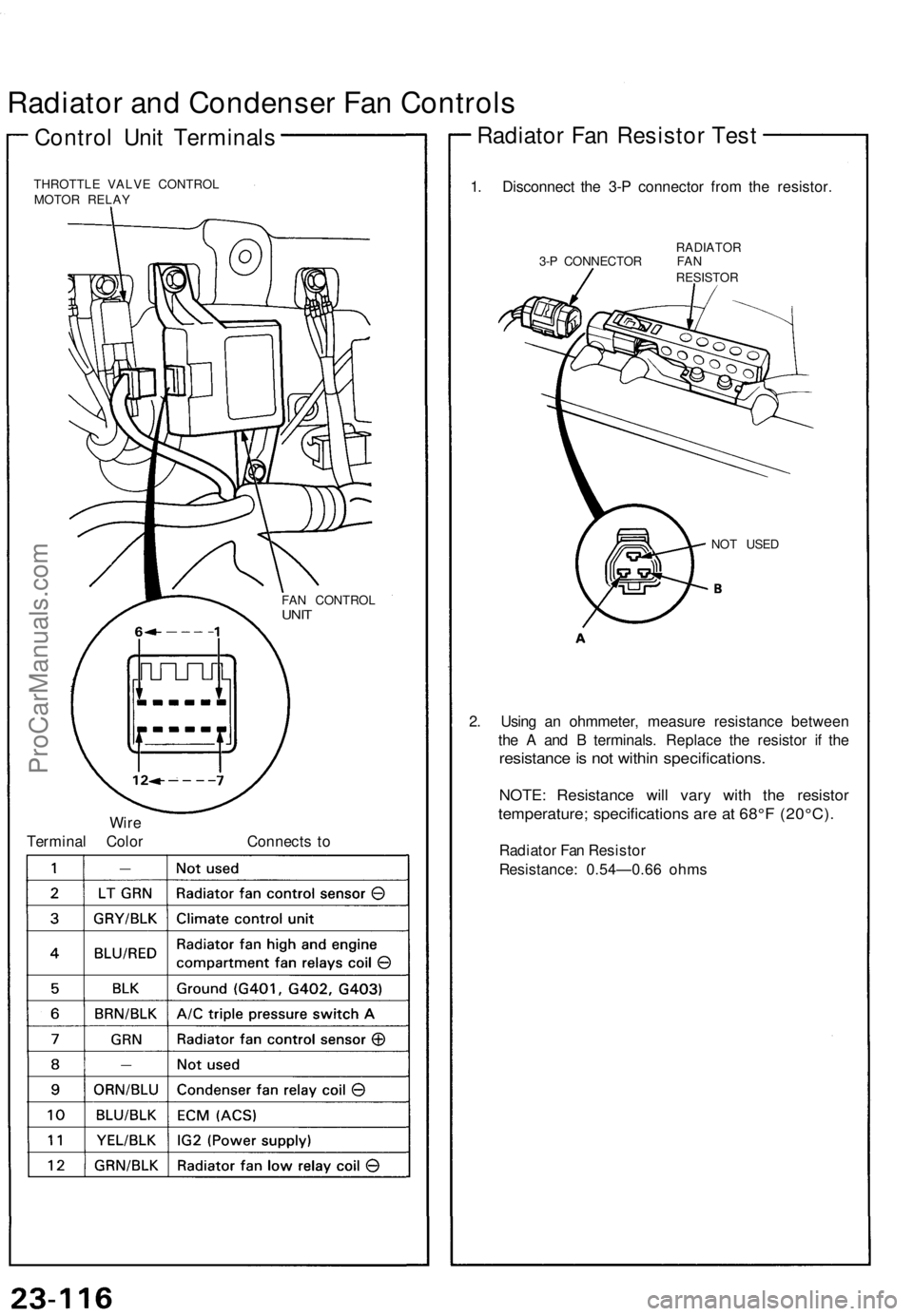
Radiator and Condenser Fan Controls
Control Unit Terminals
THROTTLE VALVE CONTROL
MOTOR RELAY
Wire
Terminal Color
Connects to
1. Disconnect the 3-P connector from the resistor.
RADIATOR
3-P CONNECTOR FAN
RESISTOR
NOT USED
2. Using an ohmmeter, measure resistance between
the A and B terminals. Replace the resistor if the
resistance is not within specifications.
NOTE: Resistance will vary with the resistor
temperature; specifications are at 68°F (20°C).
Radiator Fan Resistor
Resistance: 0.54—0.66 ohms
Radiator Fan Resistor Test
FAN CONTROL
UNITProCarManuals.com
Page 782 of 1640
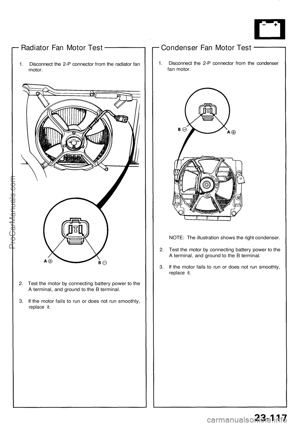
Radiator Fan Motor Test
1. Disconnect the 2-P connector from the radiator fan
motor.
2. Test the motor by connecting battery power to the
A terminal, and ground to the B terminal.
3. If the motor fails to run or does not run smoothly,
replace it.
Condenser Fan Motor Test
1. Disconnect the 2-P connector from the condenser
fan motor.
NOTE: The illustration shows the right condenser.
2. Test the motor by connecting battery power to the
A terminal, and ground to the B terminal.
3. If the motor fails to run or does not run smoothly,
replace it.ProCarManuals.com
Page 783 of 1640
Radiator an d Condense r Fa n Control s
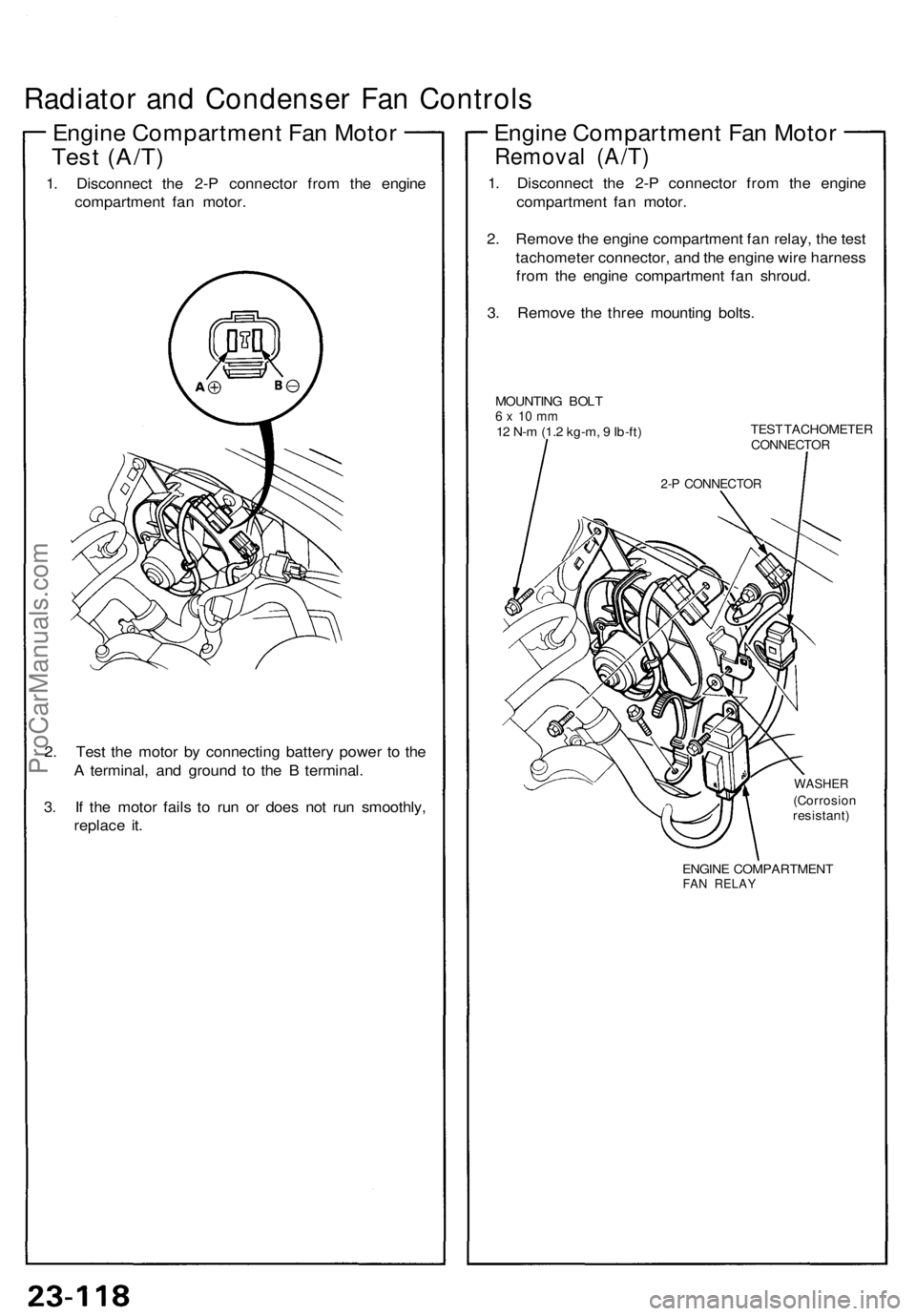
Engine Compartmen t Fa n Moto r
Tes t (A/T )
1. Disconnec t th e 2- P connecto r fro m th e engin e
compartmen t fa n motor .
2 . Tes t th e moto r b y connectin g batter y powe r t o th e
A terminal , an d groun d t o th e B terminal .
3 . I f th e moto r fail s t o ru n o r doe s no t ru n smoothly ,
replac e it .
Engin e Compartmen t Fa n Moto r
Remova l (A/T )
1. Disconnec t th e 2- P connecto r fro m th e engin e
compartmen t fa n motor .
2 . Remov e th e engin e compartmen t fa n relay, the tes t
tachomete r connector , an d th e engin e wir e harnes s
fro m th e engin e compartmen t fa n shroud .
3 . Remov e th e thre e mountin g bolts .
MOUNTIN G BOL T6 x 1 0 m m12 N- m (1. 2 kg-m , 9 Ib-ft ) TES
T TACHOMETE RCONNECTOR
WASHER(Corrosio nresistant)
ENGIN E COMPARTMEN T
FAN RELA Y
2-P CONNECTO R
ProCarManuals.com
Page 784 of 1640
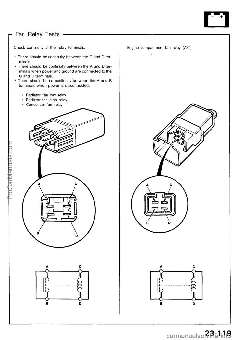
Fan Relay Tests
Check continuity at the relay terminals.
• There should be continuity between the C and D ter-
minals.
• There should be continuity between the A and B ter-
minals when power and ground are connected to the
C and D terminals.
• There should be no continuity between the A and B
terminals when power is disconnected.
• Radiator fan low relay
• Radiator fan high relay
• Condenser fan relay
Engine compartment fan relay (A/T)ProCarManuals.com
Page 785 of 1640
Radiator an d Condense r Fa n Control s
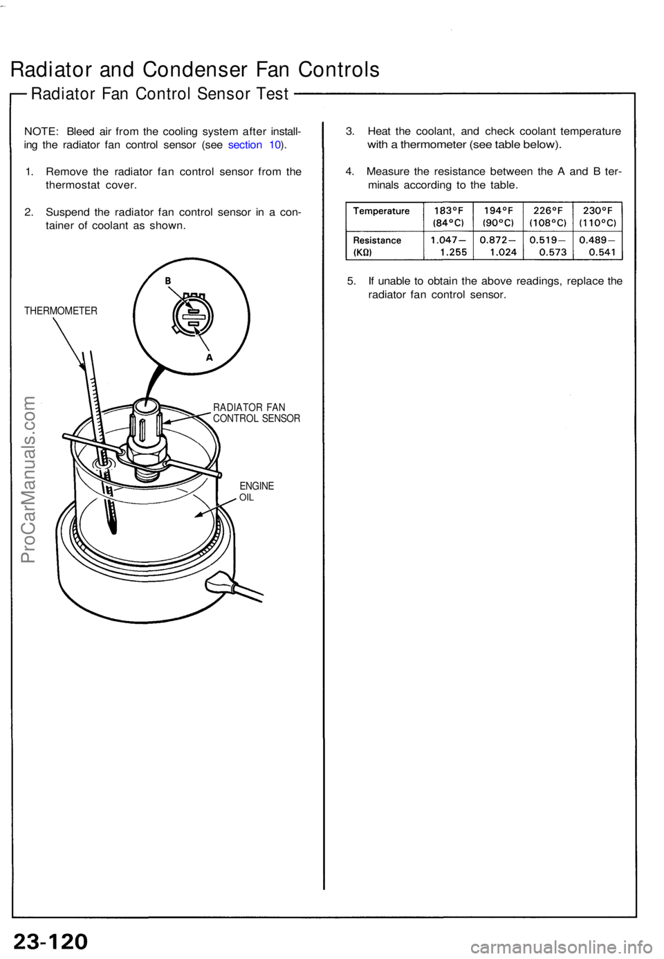
Radiator Fa n Contro l Senso r Tes t
NOTE : Blee d ai r fro m th e coolin g syste m afte r install -
in g th e radiato r fa n contro l senso r (se e sectio n 10 ).
1 . Remov e th e radiato r fa n contro l senso r fro m th e
thermosta t cover .
2 . Suspen d th e radiato r fa n contro l senso r i n a con -
taine r o f coolan t a s shown .
THERMOMETE R
RADIATOR FA NCONTRO L SENSO R
ENGIN E
OIL
3. Hea t th e coolant , an d chec k coolan t temperatur e
with a thermomete r (se e tabl e below) .
4. Measur e th e resistanc e betwee n th e A an d B ter -
minal s accordin g t o th e table .
5 . I f unabl e t o obtai n th e abov e readings , replac e th e
radiato r fa n contro l sensor .
ProCarManuals.com
Page 786 of 1640
Gauge Assembly
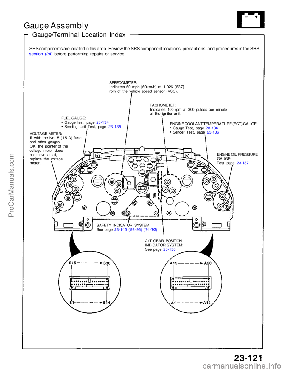
Gauge/Terminal Location Index
SRS components are located in this area. Review the SRS component locations, precautions, and procedures in the SRS
section (24) before performing repairs or service.
SPEEDOMETER:
Indicates 60 mph [60km/h] at 1.026 [637]
rpm of the vehicle speed sensor (VSS).
FUEL GAUGE: Gauge test, page 23-134 Sending Unit Test, page 23-135
VOLTAGE METER:
If, with the No. 5 (15 A) fuse
and other gauges
OK, the pointer of the
voltage meter does not move at all,
replace the voltage
meter.
SAFETY INDICATOR SYSTEM:
See page 23-145 ('93-'96) ('91-'92)A/T GEAR POSITION
INDICATOR SYSTEM:
See page 23-156 ENGINE OIL PRESSURE
GAUGE:
Test page 23-137
ENGINE COOLANT TEMPERATURE (ECT) GAUGE:
Gauge Test, page 23-136 Sender Test, page 23-136
TACHOMETER:
Indicates 100 rpm at 300 pulses per minute
of the igniter unit.ProCarManuals.com
Page 787 of 1640
Gauge Assembl y
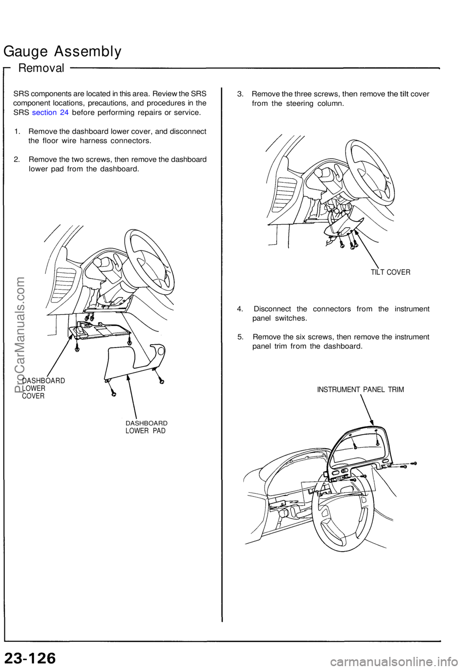
Removal
SRS component s ar e locate d in thi s area . Revie w th e SR S
componen t locations , precautions , an d procedure s i n th e
SR S sectio n 24 befor e performin g repair s o r service .
1 . Remov e th e dashboar d lowe r cover , an d disconnec t
th e floo r wir e harnes s connectors .
2 . Remov e th e tw o screws , the n remov e th e dashboar d
lowe r pa d fro m th e dashboard .
DASHBOAR DLOWER
COVE R
DASHBOAR DLOWER PA D
3. Remov e the thre e screws , then remov e the tilt cove r
fro m th e steerin g column .
TILT COVE R
4. Disconnec t th e connector s fro m th e instrumen t
pane l switches .
5 . Remov e th e si x screws , the n remov e th e instrumen t
pane l tri m fro m th e dashboard .
INSTRUMEN T PANE L TRI M
ProCarManuals.com
Page 788 of 1640
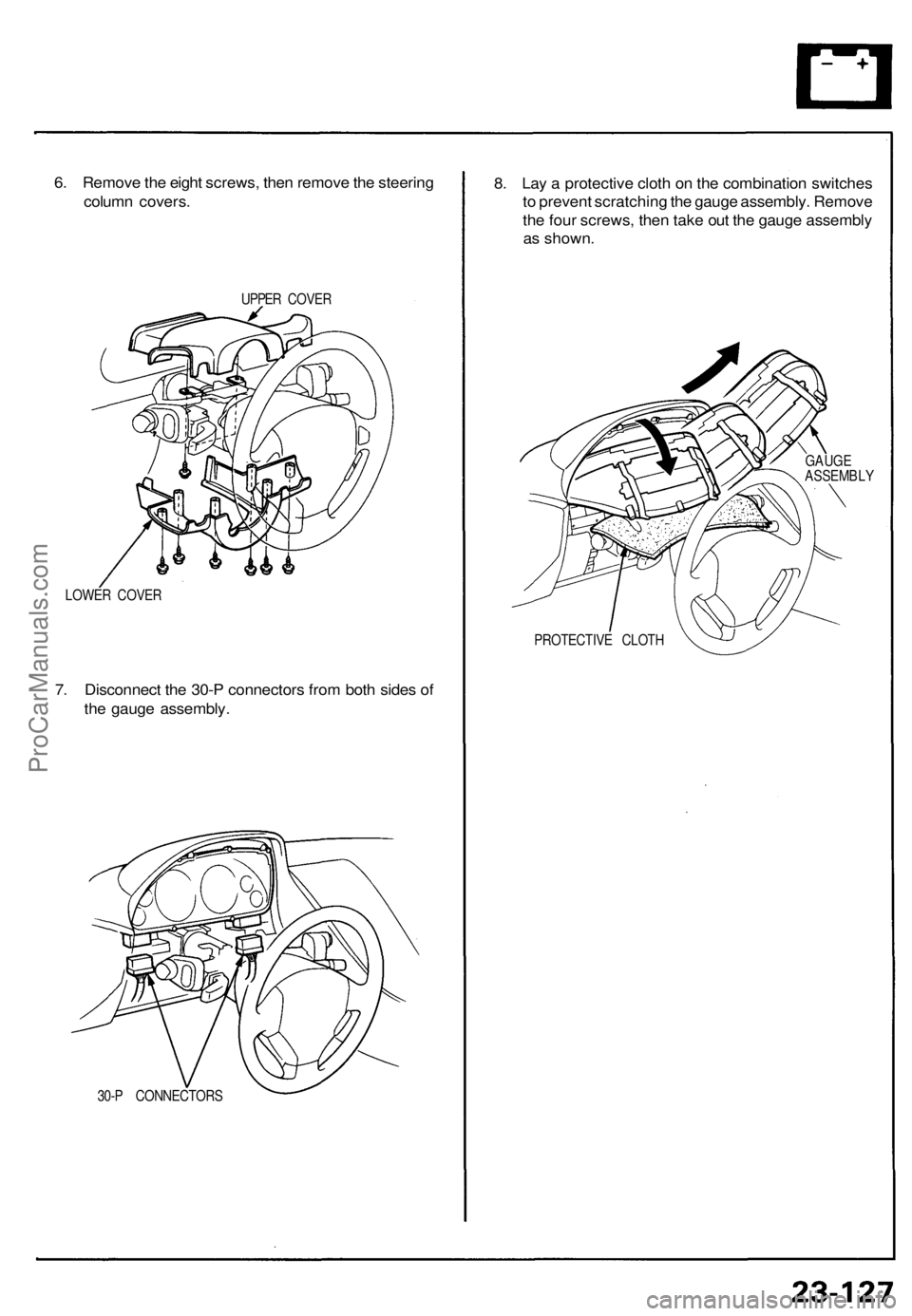
6. Remove the eight screws, then remove the steering
column covers.
UPPER COVER
LOWER COVER
7. Disconnect the 30-P connectors from both sides of
the gauge assembly.
30-P CONNECTORS
8. Lay a protective cloth on the combination switches
to prevent scratching the gauge assembly. Remove
the four screws, then take out the gauge assembly
as shown.
PROTECTIVE CLOTH
GAUGE
ASSEMBLYProCarManuals.com
Page 789 of 1640
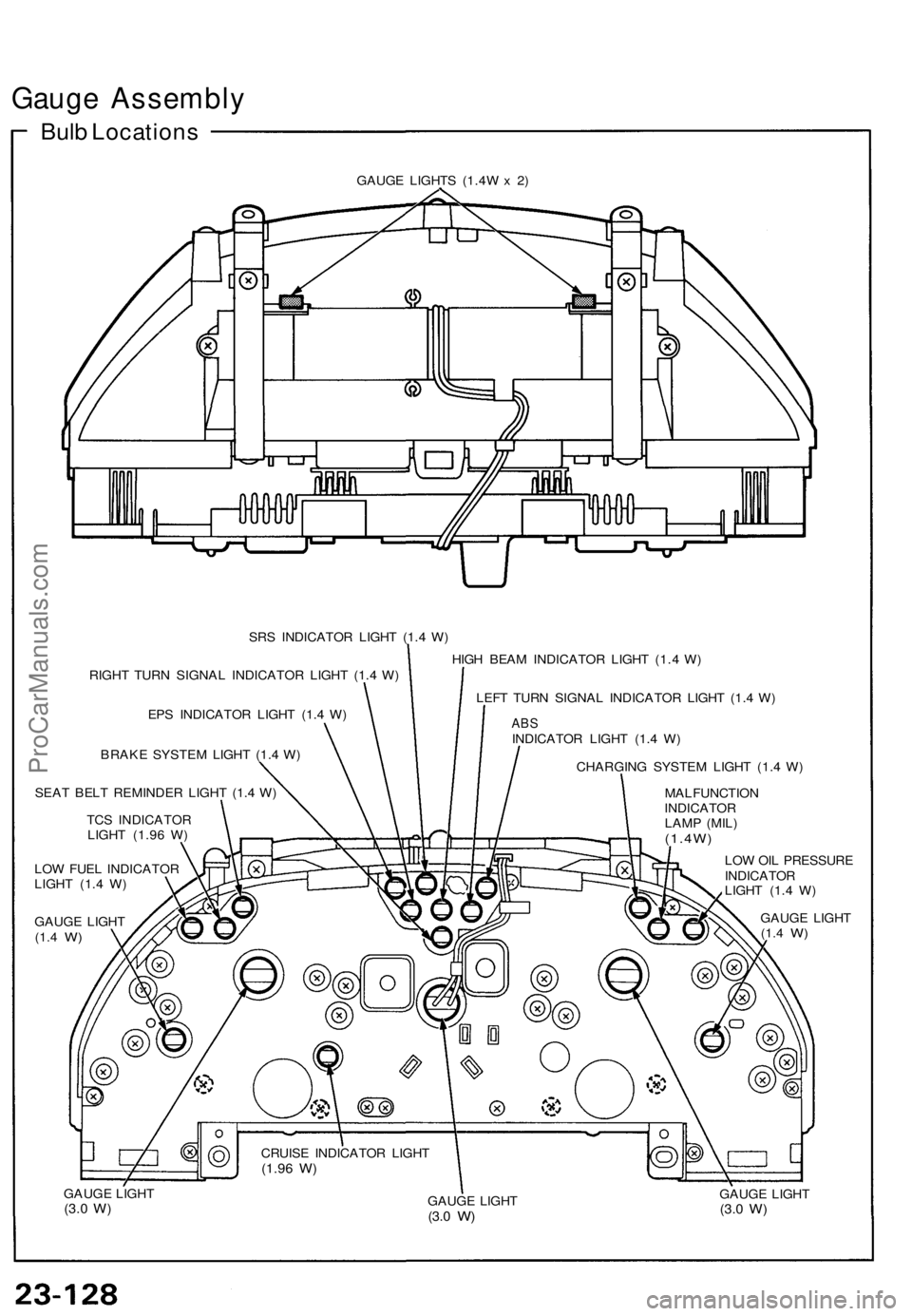
Gauge Assembly
Bulb Locations
GAUGE LIGHTS (1.4W x 2)
SRS INDICATOR LIGHT (1.4 W)
RIGHT TURN SIGNAL INDICATOR LIGHT (1.4 W)
EPS INDICATOR LIGHT (1.4 W)
BRAKE SYSTEM LIGHT (1.4 W)
SEAT BELT REMINDER LIGHT (1.4 W)
TCS INDICATOR
LIGHT (1.96 W)
LOW FUEL INDICATOR
LIGHT (1.4 W)
GAUGE LIGHT
(1.4
W)
HIGH BEAM INDICATOR LIGHT (1.4 W)
LEFT TURN SIGNAL INDICATOR LIGHT (1.4 W)
ABS
INDICATOR LIGHT (1.4 W)
CHARGING SYSTEM LIGHT (1.4 W)
MALFUNCTION
INDICATOR
LAMP (MIL)
(1.4W)
LOW OIL PRESSURE
INDICATOR
LIGHT (1.4 W)
GAUGE LIGHT
(1.4
W)
GAUGE LIGHT
(3.0
W)
GAUGE LIGHT
(3.0
W)
GAUGE LIGHT
(3.0
W)
CRUISE INDICATOR LIGHT
(1.96
W)ProCarManuals.com
Page 790 of 1640
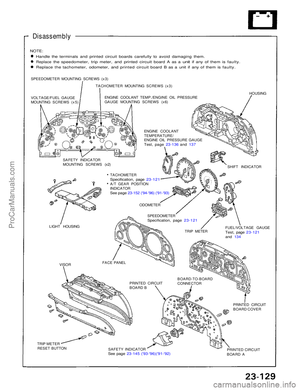
Disassembly
NOTE:
Handle the terminals and printed circuit boards carefully to avoid damaging them.
Replace
the
speedometer,
trip
meter,
and
printed
circuit
board
A as a
unit
if any of
them
is
faulty. Replace the tachometer, odometer, and printed circuit board B as a unit if any of them is faulty.
SPEEDOMETER MOUNTING SCREWS (x3) TACHOMETER MOUNTING SCREWS (x3)
VOLTAGE/FUEL GAUGE
MOUNTING SCREWS (x5) ENGINE COOLANT TEMP./ENGINE OIL PRESSURE
GAUGE MOUNTING SCREWS (x6)
HOUSING
ENGINE COOLANT
TEMPERATURE/
ENGINE OIL PRESSURE GAUGE
Test, page 23-136 and 137
SAFETY INDICATOR
MOUNTING SCREWS (x2) SHIFT INDICATOR
TACHOMETER
Specification, page 23-121
A/T GEAR POSITION
INDICATOR
See page 23-152 ('94-'96) ('91-'93)
LIGHT HOUSING
ODOMETER
SPEEDOMETER
Specification, page 23-121
TRIP METER FUEL/VOLTAGE GAUGE
Test, page 23-121
and 134
FACE PANEL PRINTED CIRCUIT
BOARD B
BOARD-TO-BOARD
CONNECTOR
PRINTED CIRCUIT
BOARD COVER
PRINTED CIRCUIT
BOARD A
SAFETY INDICATOR
See page 23-145 ('93-'96)('91-'92)
TRIP METER
RESET BUTTON
VISORProCarManuals.com
Trending: auxiliary battery location, coolant capacity, light, transmission oil, service indicator, child seat, jacking
