ACURA NSX 1991 Service Repair Manual
Manufacturer: ACURA, Model Year: 1991, Model line: NSX, Model: ACURA NSX 1991Pages: 1640, PDF Size: 60.48 MB
Page 761 of 1640
Ignition Syste m
Idle Spee d Inspectio n
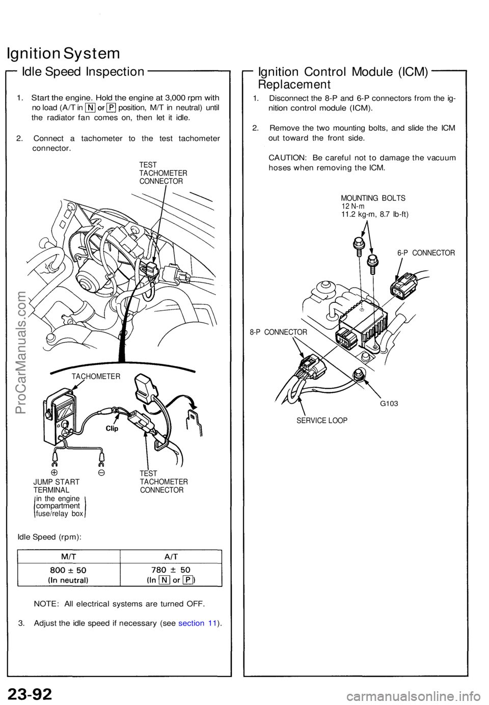
1. Star t th e engine . Hol d th e engin e a t 3,00 0 rp m wit h
no loa d (A/ T in position , M/ T in neutral ) unti l
th e radiator fan come s on , the n le t i t idle .
2 . Connec t a tachomete r t o th e tes t tachomete r
connector .
TEST
TACHOMETE R
CONNECTO R
JUMP STAR TTERMINA Lin th e engin ecompartmen tfuse/relay bo x
Idle Spee d (rpm) :
TEST
TACHOMETE R
CONNECTO R
NOTE: Al l electrica l system s ar e turne d OFF .
3 . Adjus t th e idl e spee d i f necessar y (se e sectio n 11 ).
Ignitio n Contro l Modul e (ICM )
Replacemen t
1. Disconnec t th e 8- P an d 6- P connector s fro m th e ig -
nitio n contro l modul e (ICM) .
2. Remov e th e tw o mountin g bolts , an d slid e th e IC M
ou t towar d th e fron t side .
CAUTION : B e carefu l no t t o damag e th e vacuu m
hose s whe n removin g th e ICM .
MOUNTIN G BOLT S12 N- m11.2 kg-m , 8. 7 Ib-ft )
6-P CONNECTO R
8- P CONNECTO R
G103
SERVIC E LOO P
TACHOMETE
R
ProCarManuals.com
Page 762 of 1640
Ignition Contro l Modul e (ICM ) Inpu t Tes t
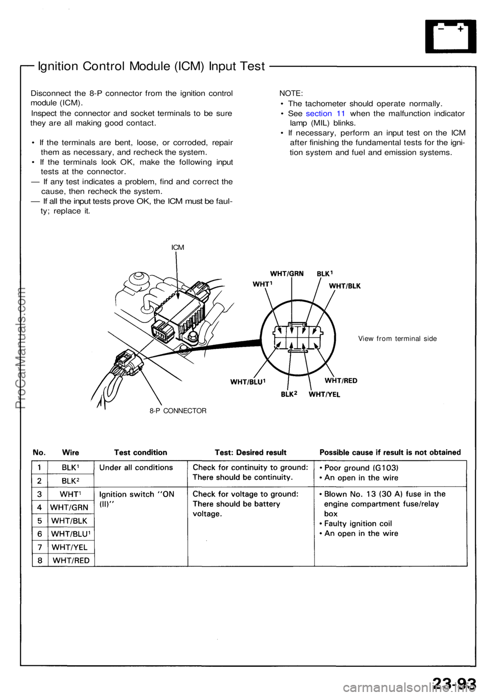
Disconnec t th e 8- P connecto r fro m th e ignitio n contro l
modul e (ICM) .
Inspec t th e connecto r an d socke t terminal s t o b e sur e
the y ar e al l makin g goo d contact .
• I f th e terminal s ar e bent , loose , o r corroded , repai r
the m a s necessary , an d rechec k th e system .
• I f th e terminal s loo k OK , mak e th e followin g inpu t
test s a t th e connector .
— If an y tes t indicate s a problem , fin d an d correc t th e
cause , the n rechec k th e system .
— If al l th e inpu t test s prov e OK , th e IC M mus t b e faul -
ty; replac e it .
IC M
NOTE :
• Th e tachomete r shoul d operat e normally .
• Se e sectio n 1 1 whe n th e malfunctio n indicato r
lam p (MIL ) blinks .
• I f necessary , perfor m a n inpu t tes t o n th e IC M
afte r finishin g th e fundamenta l test s fo r th e igni -
tio n syste m an d fue l an d emissio n systems .
View fro m termina l sid e
8-P CONNECTO R
ProCarManuals.com
Page 763 of 1640
Ignition Coil Test
1. With the ignition switch OFF, remove the ignition
coil.
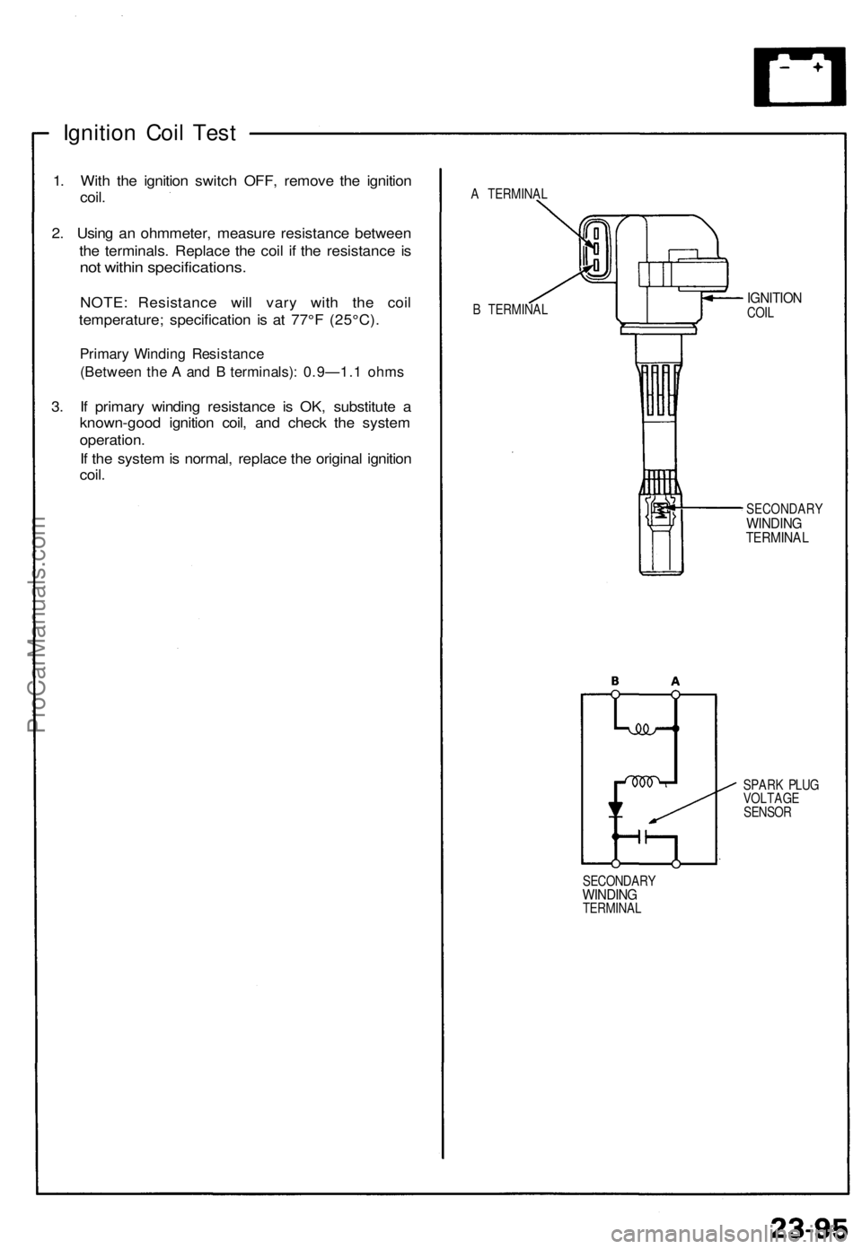
2. Using an ohmmeter, measure resistance between
the terminals. Replace the coil if the resistance is
not within specifications.
NOTE: Resistance will vary with the coil
temperature; specification is at 77°F (25°C).
Primary Winding Resistance
(Between the A and B terminals): 0.9—1.1 ohms
3. If primary winding resistance is OK, substitute a
known-good ignition coil, and check the system
operation.
If the system is normal, replace the original ignition
coil.
A TERMINAL
B TERMINAL
IGNITION
COIL
SECONDARY
WINDING
TERMINAL
SPARK PLUG
VOLTAGE
SENSOR
SECONDARY
WINDING
TERMINALProCarManuals.com
Page 764 of 1640
Ignition System
Spark Plug Inspection
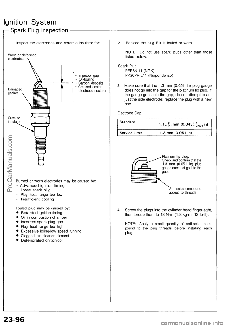
1. Inspect the electrodes and ceramic insulator for:
Worn or deformed
electrodes
Damaged
gasket
• Improper gap
• Oil-fouling
• Carbon deposits
• Cracked center
electrode insulator
Cracked
insulator
Burned or worn electrodes may be caused by:
• Advanced ignition timing
• Loose spark plug
• Plug heat range too low
• Insufficient cooling
Fouled plug may be caused by:
Retarded ignition timing
Oil in combustion chamber
Incorrect spark plug gap
Plug heat range too high
Excessive idling/low speed running
Clogged air cleaner element
Deteriorated ignition coil
2. Replace the plug if it is fouled or worn.
NOTE: Do not use spark plugs other than those
listed below.
Spark Plug:
PFR6N-11 (NGK)
PK20PR-L11 (Nippondenso)
3. Make sure that the 1.3 mm (0.051 in) plug gauge
does not go into the gap for the platinum tip plug. If
the gauge goes into the gap, do not attempt to ad-
just the side electrode; replace the plug with a new
one.
Electrode Gap:
Platinum tip plug:
Check and confirm that the
1.3 mm (0.051 in) plug
gauge does not go into the
gap.
Anti-seize compound
applied to threads
4. Screw the plugs into the cylinder head finger-tight,
then torque them to 18 N-m (1.8 kg-m, 13 Ib-ft).
NOTE: Apply a small quantity of anti-seize com-
pound to the plug threads before installing each
plug.ProCarManuals.com
Page 765 of 1640
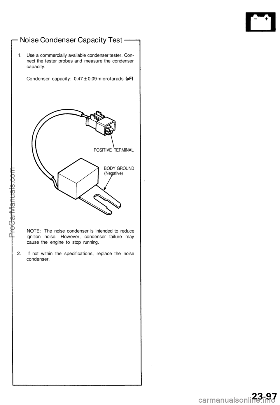
Noise Condenser Capacity Test
1. Use a commercially available condenser tester. Con-
nect the tester probes and measure the condenser
capacity.
Condenser capacity: 0.47 ± 0.09 microfarads
POSITIVE TERMINAL
BODY GROUND
(Negative)
NOTE: The noise condenser is intended to reduce
ignition noise. However, condenser failure may
cause the engine to stop running.
2. If not within the specifications, replace the noise
condenser.ProCarManuals.com
Page 766 of 1640
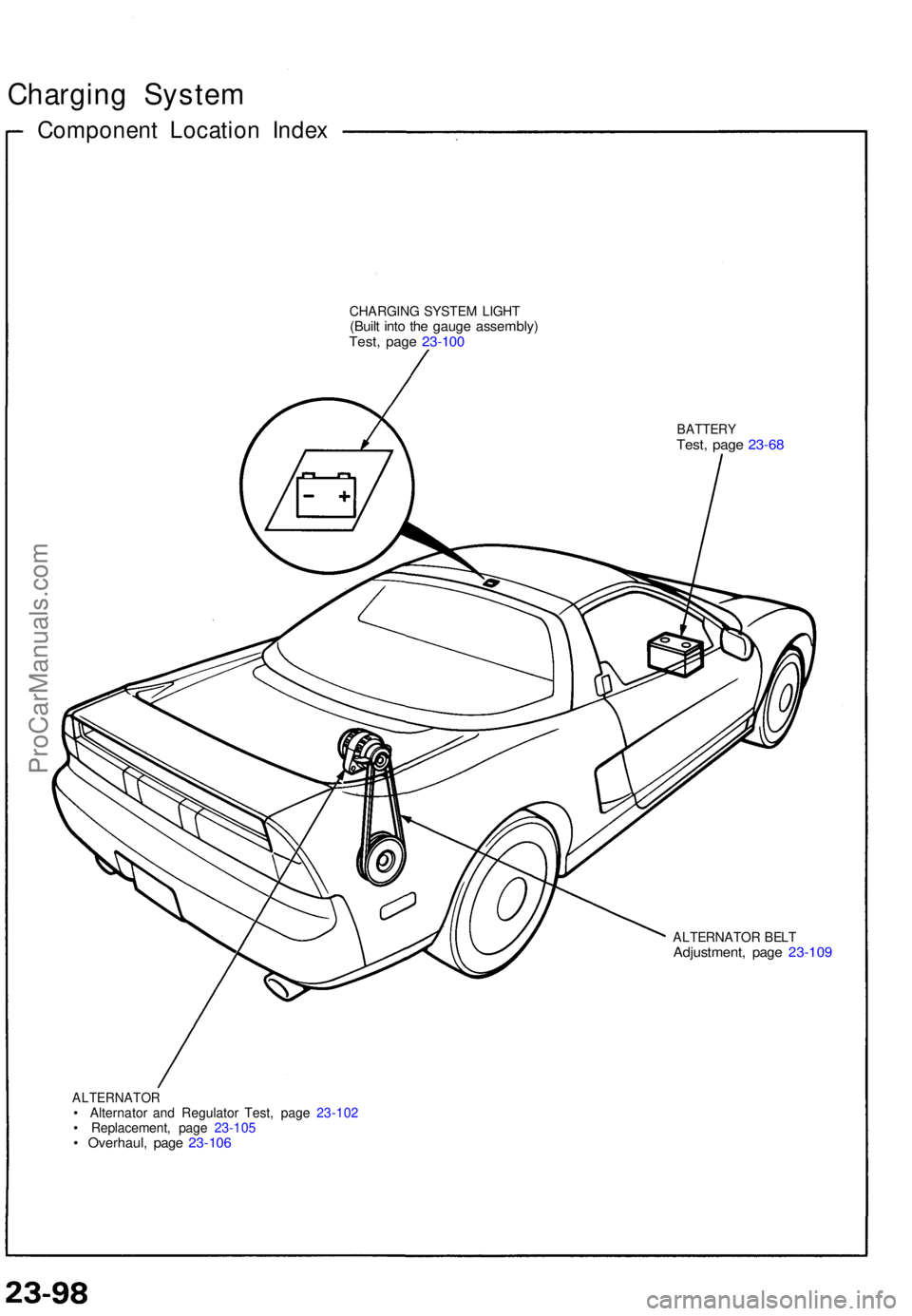
Charging Syste m
Componen t Locatio n Inde x
CHARGIN G SYSTE M LIGH T(Built int o th e gaug e assembly )Test, pag e 23-10 0
BATTER YTest, pag e 23-6 8
ALTERNATO R BEL TAdjustment , pag e 23-10 9
ALTERNATO R• Alternato r an d Regulato r Test , pag e 23-10 2
• Replacement , pag e 23-10 5
• Overhaul , pag e 23-10 6
ProCarManuals.com
Page 767 of 1640
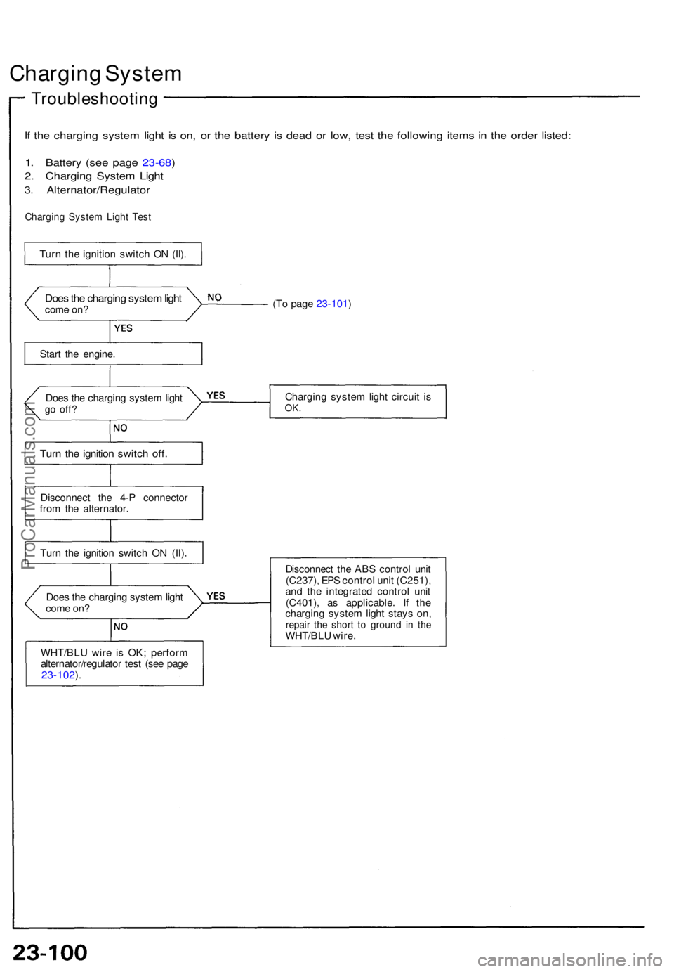
Charging Syste m
Troubleshootin g
If th e chargin g syste m ligh t i s on , o r th e batter y i s dea d o r low , tes t th e followin g item s i n th e orde r listed :
1. Batter y (se e pag e 23-68 )
2. Chargin g Syste m Ligh t
3. Alternator/Regulato r
Charging Syste m Ligh t Tes t
Does th e chargin g syste m ligh tcom e on ?
Star t th e engine .
Doe s th e chargin g syste m ligh t
go off ?
Turn th e ignitio n switc h off .
Disconnec t th e 4- P connecto r
fro m th e alternator .
Tur n th e ignitio n switc h O N (II) .
WHT/BL U wir e i s OK ; perfor m
alternator/regulato r tes t (se e pag e
23-102 ).
Doe s th e chargin g syste m ligh t
com e on ? (T
o pag e 23-101 )
Chargin g syste m ligh t circui t i s
OK .
Disconnec t th e AB S contro l uni t
(C237) , EP S contro l uni t (C251) ,
an d th e integrate d contro l uni t
(C401) , a s applicable . I f th e
chargin g syste m ligh t stay s on ,
repai r th e shor t t o groun d i n th eWHT/BL U wire .
Tur
n th e ignitio n switc h O N (II) .
ProCarManuals.com
Page 768 of 1640
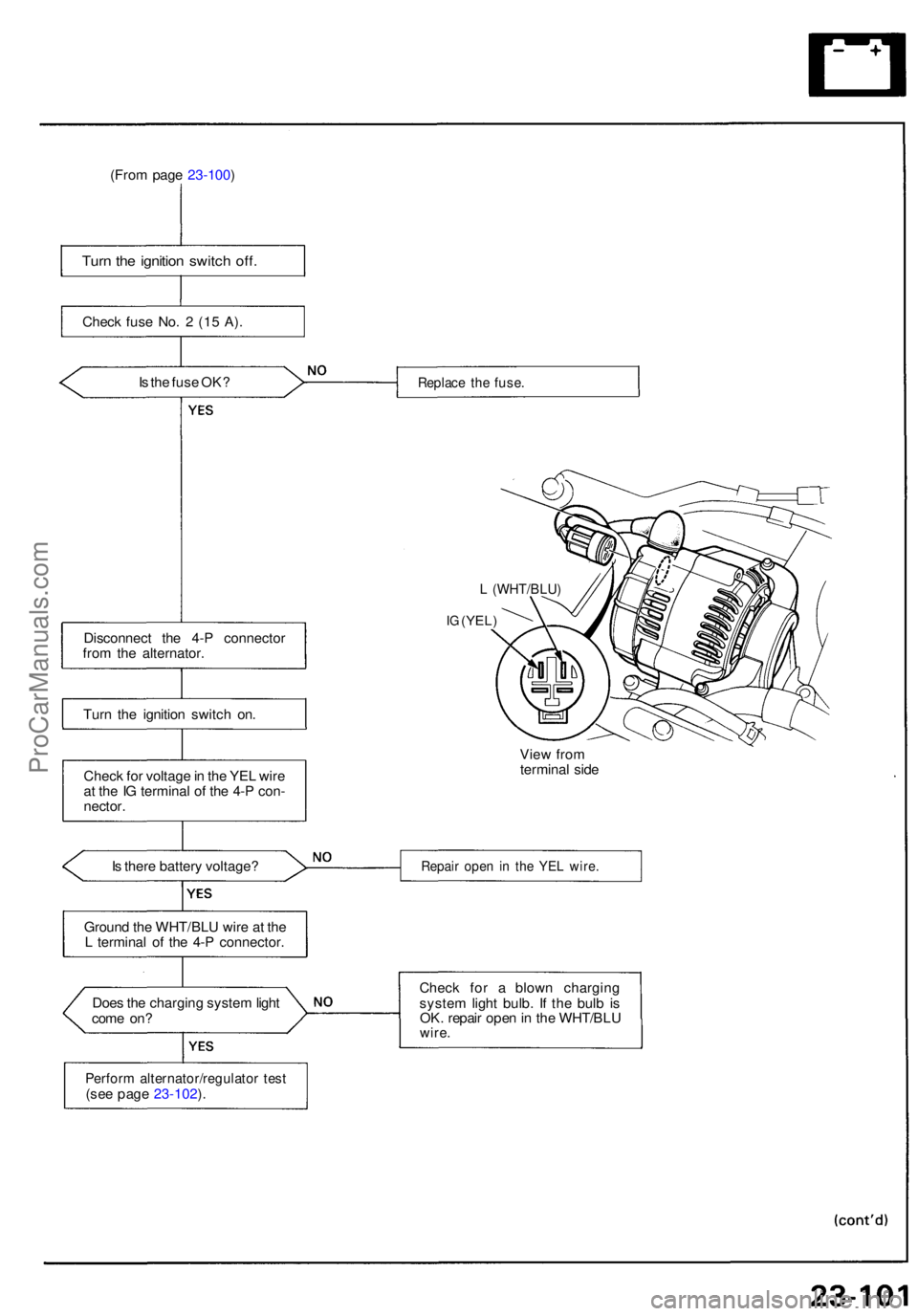
(From pag e 23-100 )
Turn th e ignitio n switc h off .
Chec k fus e No . 2 (1 5 A) .
I s th e fus e OK ?
Disconnec t th e 4- P connecto r
fro m th e alternator .
Tur n th e ignitio n switc h on .
Chec k fo r voltag e in th e YE L wir e
a t th e IG termina l o f th e 4- P con -
nector .
I s ther e batter y voltage ?
Groun d th e WHT/BL U wire at th e
L termina l o f th e 4- P connector .
Doe s th e chargin g syste m ligh t
com e on ?
Perfor m alternator/regulato r tes t(see pag e 23-102 ).
Replac e th e fuse .
L (WHT/BLU )
IG (YEL )
View fro m
termina l sid e
Repai r ope n i n th e YE L wire .
Check fo r a blow n chargin g
syste m ligh t bulb . I f th e bul b is
OK . repai r ope n in th e WHT/BL U
wire.
ProCarManuals.com
Page 769 of 1640
Charging System
Troubleshooting
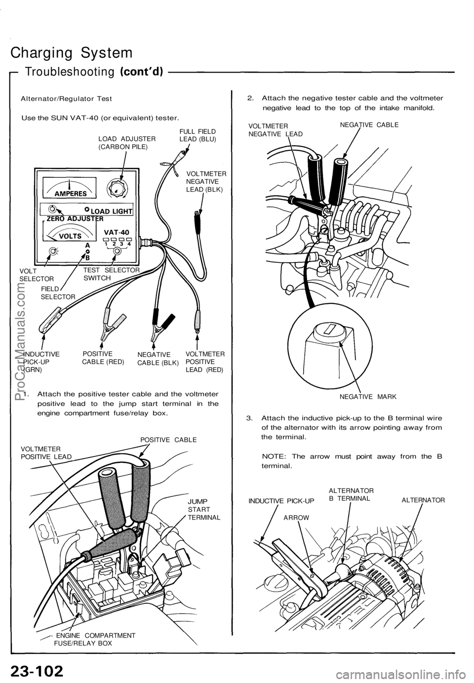
Alternator/Regulator Test
Use the SUN VAT-40 (or equivalent) tester.
2. Attach the negative tester cable and the voltmeter
negative lead to the top of the intake manifold.
LOAD ADJUSTER
(CARBON PILE)
FULL FIELD
LEAD (BLU)
VOLTMETER
NEGATIVE
LEAD (BLK)
VOLT
SELECTOR
FIELD
SELECTOR
INDUCTIVE
PICK-UP
(GRN)
POSITIVE
CABLE (RED)
NEGATIVE
CABLE (BLK)
VOLTMETER
POSITIVE
LEAD (RED)
1. Attach the positive tester cable and the voltmeter
positive lead to the jump start terminal in the
engine compartment fuse/relay box.
POSITIVE CABLE
VOLTMETER
POSITIVE LEAD
JUMP
START
TERMINAL
- ENGINE COMPARTMENT
FUSE/RELAY BOX
VOLTMETER
NEGATIVE LEAD
NEGATIVE CABLE
NEGATIVE MARK
3. Attach the inductive pick-up to the B terminal wire
of the alternator with its arrow pointing away from
the terminal.
NOTE: The arrow must point away from the B
terminal.
INDUCTIVE PICK-UP
ARROW
ALTERNATOR
B TERMINAL
ALTERNATOR
TEST SELECTOR
SWITCHProCarManuals.com
Page 770 of 1640
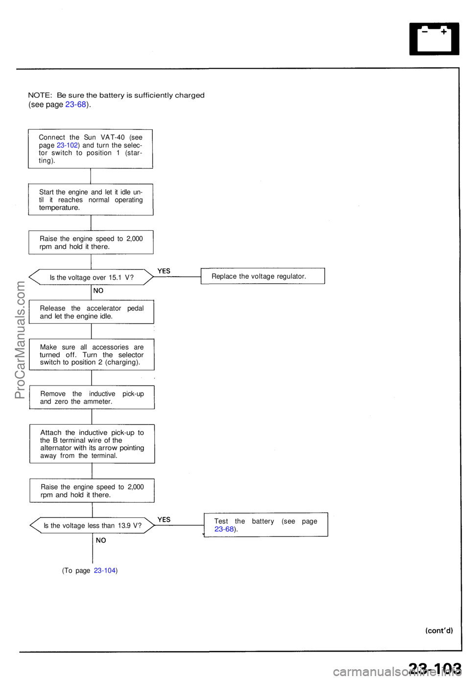
NOTE: B e sur e th e batter y is sufficientl y charge d
(see pag e 23-68 ).
Connec t th e Su n VAT-4 0 (se e
pag e 23-102 ) an d tur n th e selec -
to r switc h t o positio n 1 (star -
ting) .
Star t th e engin e an d le t i t idl e un -
ti l i t reache s norma l operatin g
temperature .
Raise th e engin e spee d t o 2,00 0rpm an d hol d i t there .
Is th e voltag e ove r 15. 1 V ?
Releas e th e accelerato r peda l
and le t th e engin e idle .
Mak e sur e al l accessorie s ar eturne d off . Tur n th e selecto rswitch t o positio n 2 (charging) .
Remove th e inductiv e pick-u p
an d zer o th e ammeter .
Attach th e inductiv e pick-u p t oth e B termina l wir e o f th ealternato r wit h it s arro w pointin gaway fro m th e terminal .
Rais e th e engin e spee d t o 2,00 0
rpm an d hol d i t there .
Is th e voltag e les s tha n 13. 9 V ?
(T o pag e 23-104 ) Replac
e th e voltag e regulator .
Tes t th e batter y (se e pag e23-68).
ProCarManuals.com