ACURA NSX 1991 Service Repair Manual
Manufacturer: ACURA, Model Year: 1991, Model line: NSX, Model: ACURA NSX 1991Pages: 1640, PDF Size: 60.48 MB
Page 801 of 1640
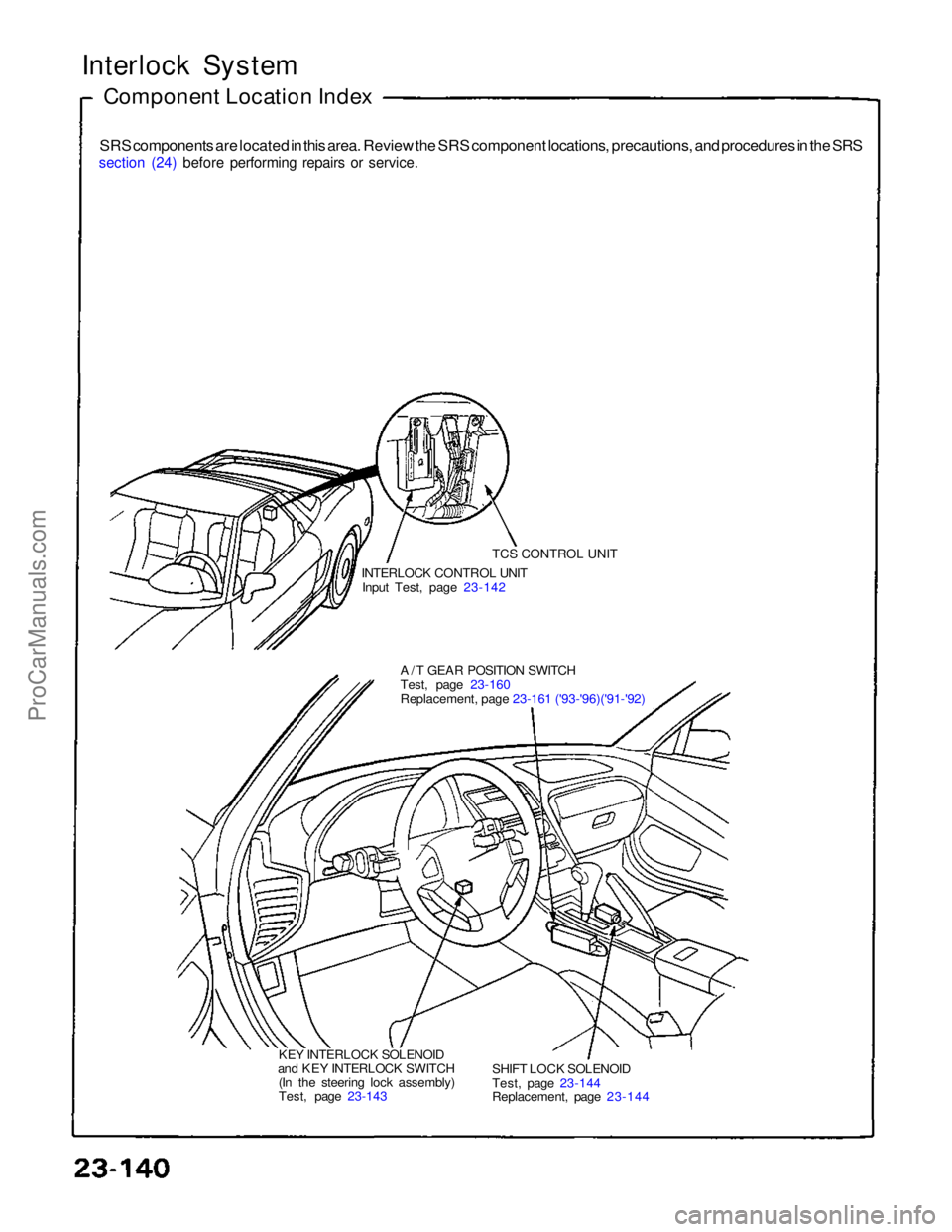
Interlock System
Component Location Index
SRS components are located in this area. Review the SRS component locations, precautions, and procedures in the SRS
section (24) before performing repairs or service.
TCS CONTROL UNIT
INTERLOCK CONTROL UNIT
Input Test, page 23-142
A/T GEAR POSITION SWITCH
Test, page 23-160
Replacement, page 23-161 ('93-'96)('91-'92)
KEY INTERLOCK SOLENOID
and KEY INTERLOCK SWITCH (In the steering lock assembly)
Test, page 23-143 SHIFT LOCK SOLENOID
Test, page 23-144
Replacement, page 23-144ProCarManuals.com
Page 802 of 1640
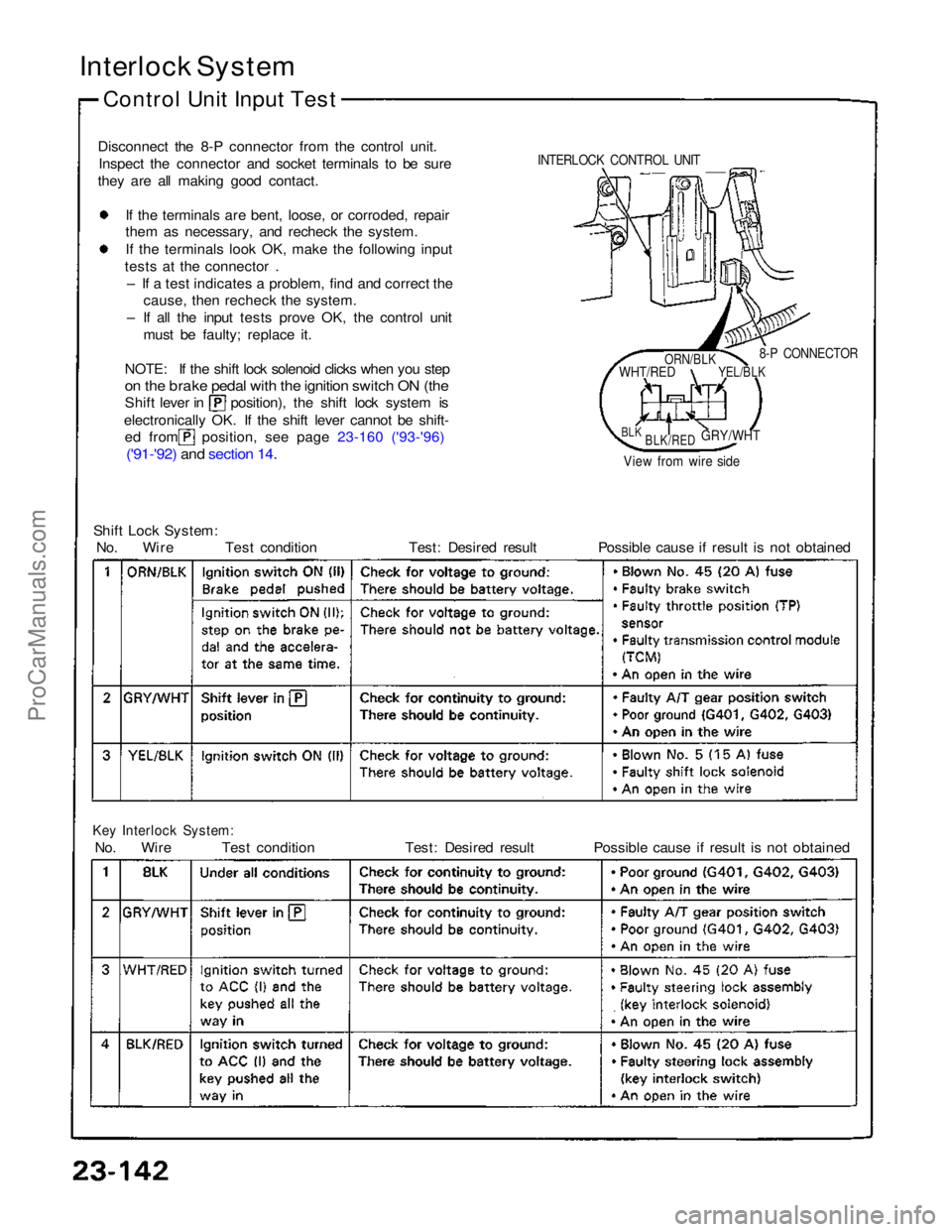
Interlock System
Control Unit Input Test
Disconnect the 8-P connector from the control unit. Inspect the connector and socket terminals to be sure
they are all making good contact.
If the terminals are bent, loose, or corroded, repair
them as necessary, and recheck the system.
I
f
the terminals look OK, make the following input
tests at the connector .
– If a test indicates a problem, find and correct the cause, then recheck the system.
– If all the input tests prove OK, the control unit must be faulty; replace it.
NOTE: If the shift lock solenoid clicks when you step
on the brake pedal with the ignition switch ON (the
Shift lever in position), the shift lock system is
electronically OK. If the shift lever cannot be shift-
ed from position, see page 23-160 ('93-'96)
('91-'92) and section 14
.
Shift Lock System:
No. Wire Test condition Test: Desired result Possible cause if result is not obtained
Key Interlock System:
No. Wire Test condition Test: Desired result Possible cause if result is not obtained
8-P CONNECTOR
View from wire side
INTERLOCK CONTROL UNIT
ORN/BLK
WHT/RED
YEL/BLK
BLK
BLK/RED
GRY/WHTProCarManuals.com
Page 803 of 1640
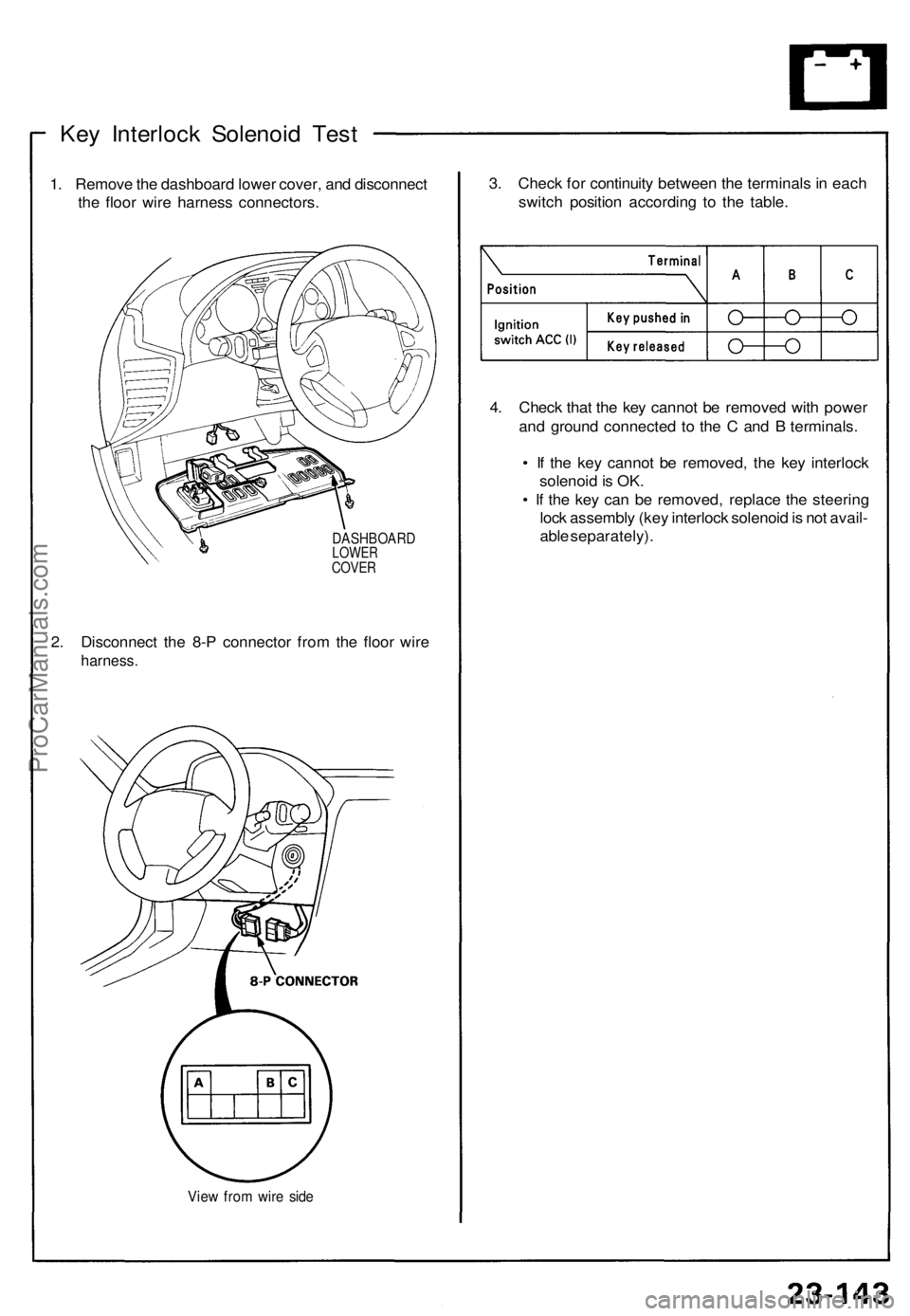
Key Interloc k Solenoi d Tes t
1. Remov e th e dashboard lower cover , an d disconnec t
th e floo r wir e harnes s connectors .
DASHBOAR DLOWERCOVER
2. Disconnec t th e 8- P connecto r fro m th e floo r wir e
harness .
View fro m wir e sid e
3. Chec k fo r continuit y betwee n th e terminal s in eac h
switc h positio n accordin g t o th e table.
4 . Chec k tha t th e ke y canno t b e remove d wit h powe r
an d groun d connecte d t o th e C an d B terminals .
• I f th e ke y canno t b e removed , th e ke y interloc k
solenoi d is OK .
• I f th e ke y ca n b e removed , replac e th e steerin g
loc k assembl y (ke y interloc k solenoi d is no t avail -
abl e separately) .
ProCarManuals.com
Page 804 of 1640
Interlock System
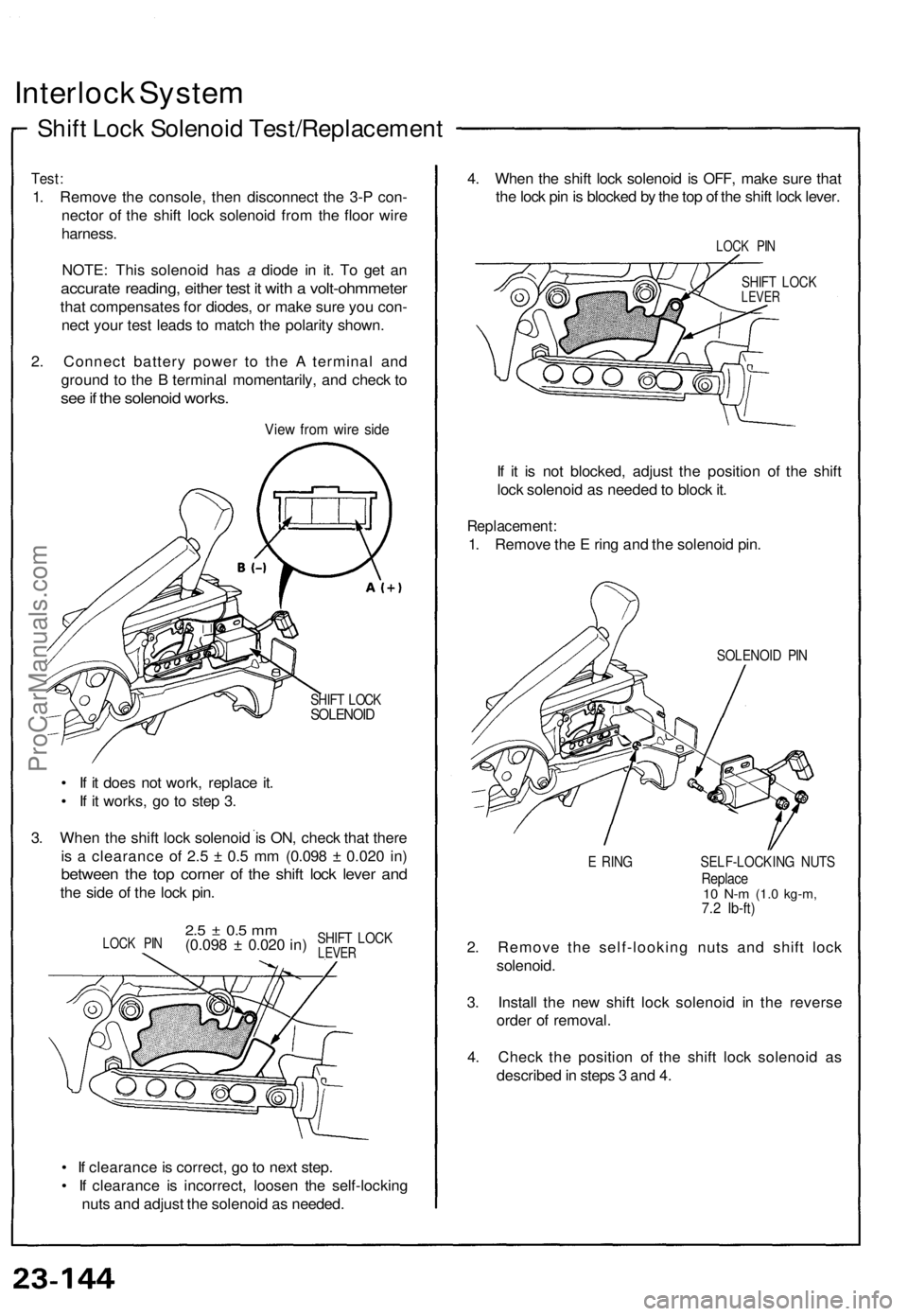
Shift Lock Solenoid Test/Replacement
Test:
1. Remove the console, then disconnect the 3-P con-
nector of the shift lock solenoid from the floor wire
harness.
NOTE: This solenoid has a diode in it. To get an
accurate reading, either test it with a volt-ohmmeter
that compensates for diodes, or make sure you con-
nect your test leads to match the polarity shown.
2. Connect battery power to the A terminal and
ground to the B terminal momentarily, and check to
see if the solenoid works.
View from wire side
SHIFT LOCK
SOLENOID
• If it does not work, replace it.
• If it works, go to step 3.
3. When the shift lock solenoid is ON, check that there
is a clearance of 2.5 ± 0.5 mm (0.098 ± 0.020 in)
between the top corner of the shift lock lever and
the side of the lock pin.
• If clearance is correct, go to next step.
• If clearance is incorrect, loosen the self-locking
nuts and adjust the solenoid as needed.
4. When the shift lock solenoid is OFF, make sure that
the lock pin is blocked by the top of the shift lock lever.
LOCK PIN
SHIFT LOCK
LEVER
If it is not blocked, adjust the position of the shift
lock solenoid as needed to block it.
Replacement:
1. Remove the E ring and the solenoid pin.
SOLENOID PIN
E RING SELF-LOCKING NUTS
Replace
10 N-m
(1.0 kg-m,
7.2 Ib-ft)
2. Remove the self-looking nuts and shift lock
solenoid.
3. Install the new shift lock solenoid in the reverse
order of removal.
4. Check the position of the shift lock solenoid as
described in steps 3 and 4.
LOCK PIN
2.5 ± 0.5 mm
(0.098 ± 0.020 in)
SHIFT LOCK
LEVERProCarManuals.com
Page 805 of 1640
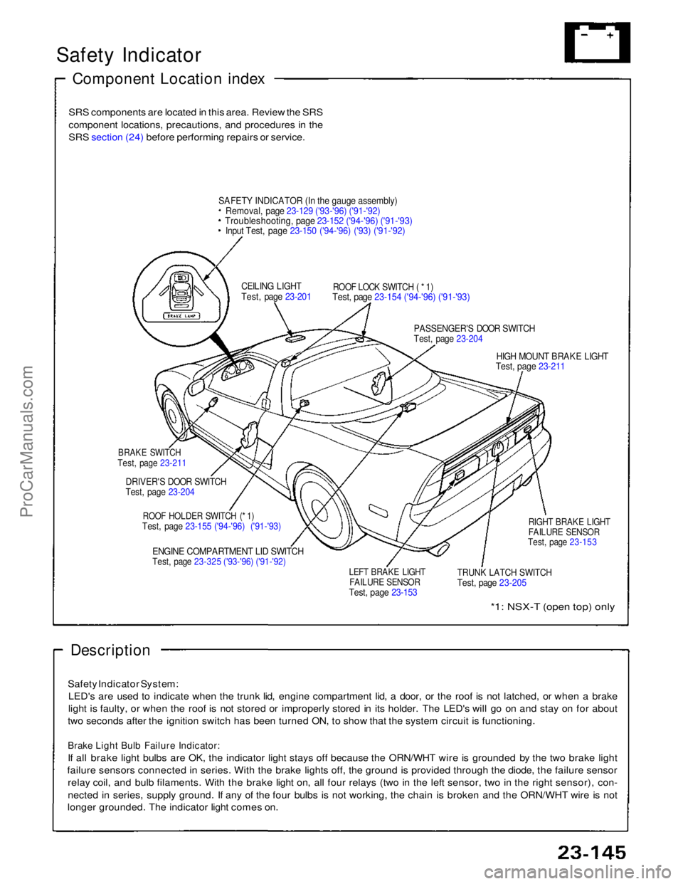
Safety Indicator
Component Location index
SRS components are located in this area. Review the SRS
component locations, precautions, and procedures in the
SRS section (24) before performing repairs or service.
SAFET
Y
INDICATOR (In the gauge assembly)
Removal, page 23-129 ('93-'96) ('91-'92)
Troubleshooting, page 23-152 ('94-'96) ('91-'93)
Input Test, page 23-150 ('94-'96) ('93) ('91-'92)
CEILING LIGHT
Test, page 23-201
ROOF LOCK SWITCH ( * 1)
Test, page 23-154 ('94-'96) ('91-'93)
PASSENGER'S DOOR SWITCH
Test, page 23-204
HIGH MOUNT BRAKE LIGHT
Test, page 23-211
BRAKE SWITCH
Test, page 23-211
DRIVER'S DOOR SWITCH
Test, page 23-204
ROOF HOLDER SWITCH (* 1)
Test, page 23-155 ('94-'96) ('91-'93)
ENGINE COMPARTMENT LID SWITCH
Test, page 23-325 ('93-'96) ('91-'92)
LEFT BRAKE LIGHT
FAILURE SENSOR
Test, page 23-153
TRUNK LATCH SWITCH
Test, page 23-205
RIGHT BRAKE LIGHT
FAILURE SENSOR
Test, page 23-153
*1: NSX-T (open top) only
Description
Safety Indicator System: LED's are used to indicate when the trunk lid, engine compartment lid, a door, or the roof is not latched, or when a brake
light is faulty, or when the roof is not stored or improperly stored in its holder. The LED's will go on and stay on for about
two seconds after the ignition switch has been turned ON, to show that the system circuit is functioning.
Brake Light Bulb Failure Indicator:
If all brake light bulbs are OK, the indicator light stays off because the ORN/WHT wire is grounded by the two brake light
failure sensors connected in series. With the brake lights off, the ground is provided through the diode, the failure sensor relay coil, and bulb filaments. With the brake light on, all four relays (two in the left sensor, two in the right sensor), con-
nected in series, supply ground. If any of the four bulbs is not working, the chain is broken and the ORN/WHT wire is not
longer grounded. The indicator light comes on.ProCarManuals.com
Page 806 of 1640
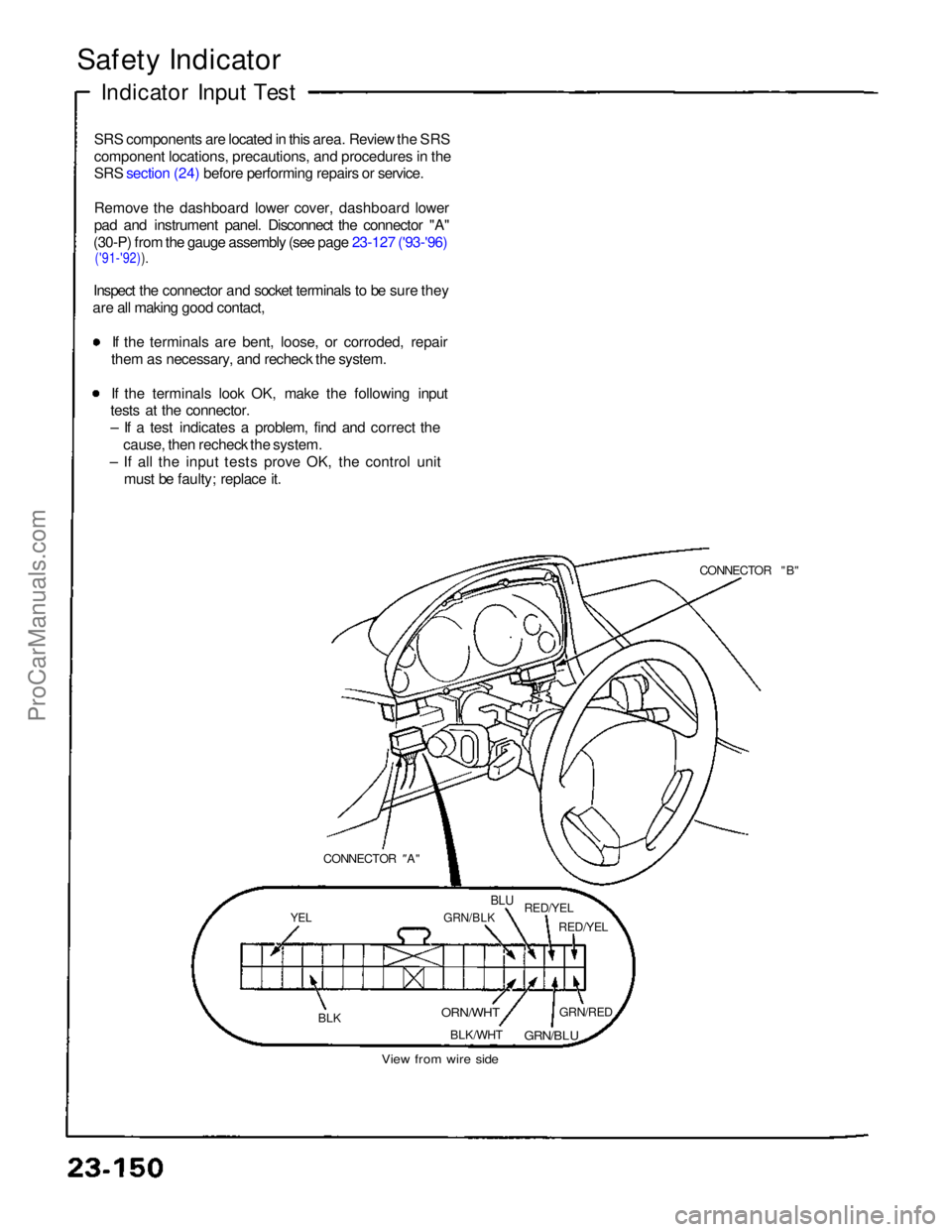
Safety Indicator
Indicator Input Test
SRS components are located in this area. Review the SRS
component locations, precautions, and procedures in the
SRS section (24) before performing repairs or service.
Remove the dashboard lower cover, dashboard lower
pad and instrument panel. Disconnect the connector "A"
(30-P) from the gauge assembly (see page 23-127 ('93-'96)
('91-'92)).
Inspect the connector and socket terminals to be sure they
are all making good contact,
If the terminals are bent, loose, or corroded, repair
them as necessary, and recheck the system. If the terminals look OK, make the following input
tests at the connector.
– If a test indicates a problem, find and correct the
cause, then recheck the system.
– If all the input tests prove OK, the control unit must be faulty; replace it.
CONNECTOR "B"
CONNECTOR "
A"
YEL
GRN/BLK
BLU
RED/YEL
RED/YEL
BLK
ORN/WHT
BLK/WHT GRN/RED
GRN/BLU
View from wire sideProCarManuals.com
Page 807 of 1640
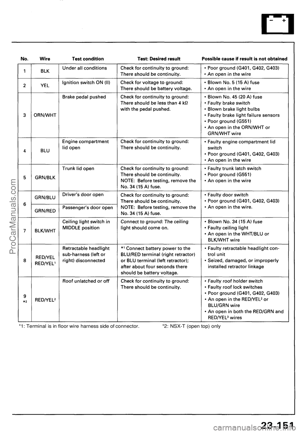
*1: Terminal is in floor wire harness side of connector. *2: NSX-T (open top) onlyProCarManuals.com
Page 808 of 1640
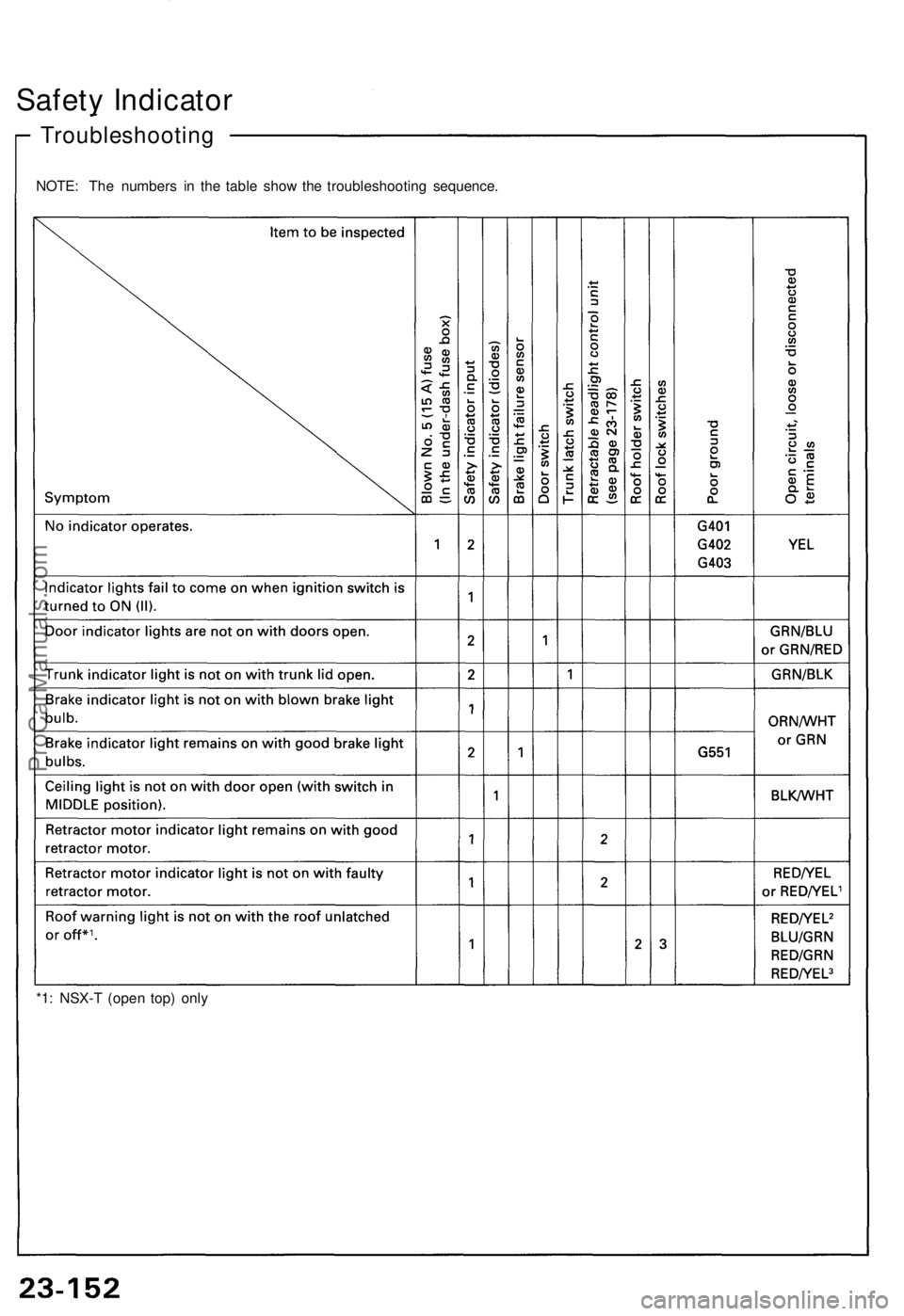
Safety Indicato r
*1: NSX- T (ope n top ) onl y
Troubleshootin g
NOTE: Th e number s i n th e tabl e sho w th e troubleshootin g sequence .
ProCarManuals.com
Page 809 of 1640
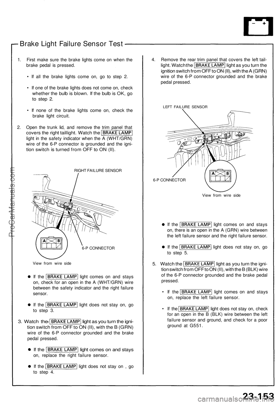
Brake Ligh t Failur e Senso r Tes t
1. Firs t mak e sur e th e brak e light s com e o n whe n th e
brak e peda l i s pressed .
• I f al l th e brak e light s com e on , g o t o ste p 2 .
• I f on e o f th e brak e light s doe s no t com e on , chec k
whethe r th e bul b is blown . I f th e bul b is OK , g o
to ste p 2 .
• I f non e of the brak e light s com e on , chec k th e
brak e ligh t circui t.
2 . Ope n th e trun k lid , an d remov e th e tri m pane l tha t
cover s th e righ t taillight . Watc h th e
ligh t i n th e safet y indicato r whe n th e A (WHT/GRN )
wir e o f th e 6- P connecto r i s grounde d an d th e igni -
tion switc h is turne d fro m OF F to O N (II) .
RIGH T FAILUR E SENSO R
6- P CONNECTO R
Vie w fro m wir e sid e
If th e ligh t come s o n an d stay s
on , chec k fo r a n ope n in th e A (WHT/GRN ) wir e
betwee n th e safet y indicato r an d th e righ t failur e
sensor .
If th e ligh t doe s no t sta y on , g o
t o ste p 3 .
3. Watc h th e ligh t a s yo u tur n th e igni -
tion switc h fro m OF F to O N (II) , wit h th e B (GRN )
wire o f th e 6- P connecto r grounde d an d th e brak e
peda l pressed .
If th e ligh t come s o n an d stay s
on, replac e th e righ t failur e sensor .
If th e ligh t doe s no t sta y o n , g o
t o ste p 4 . 4
. Remov e th e rea r tri m pane l tha t cover s th e lef t tail -
light . Watc h th e ligh t a s yo u tur n th e
ignitio n switc h fro m OF F to O N (II) , wit h th e A (GRN )
wire o f th e 6- P connecto r grounde d an d th e brak e
peda l pressed .
LEFT FAILUR E SENSO R
6-P CONNECTO R
View fro m wir e sid e
If th e ligh t come s o n an d stay s
on , ther e is a n ope n in th e A (GRN ) wir e betwee n
th e lef t failur e senso r an d th e righ t failur e sensor .
If th e ligh t doe s no t sta y on , g o
t o ste p 5 .
5. Watc h th e ligh t a s yo u tur n th e igni -
tion switc h fro m OF F to O N (II) , wit h th e B (BLK ) wir e
of th e 6- P connecto r grounde d an d th e brak e peda l
pressed .
• I f th e ligh t come s o n an d stay s
on , replac e th e lef t failur e sensor .
• I f th e ligh t doe s no t sta y on , chec k
fo r a n ope n in th e B (BLK ) wir e betwee n th e lef t
failur e senso r an d ground , an d chec k fo r a poo r
groun d a t G551 .
ProCarManuals.com
Page 810 of 1640
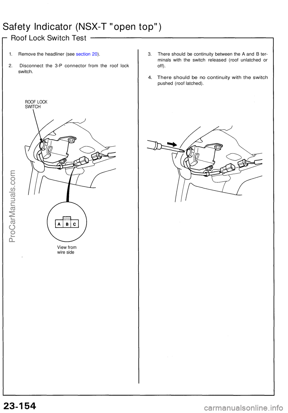
Safety Indicato r (NSX- T "ope n top" )
Roof Loc k Switc h Tes t
1. Remov e th e headline r (se e sectio n 20 ).
2 . Disconnec t th e 3- P connecto r fro m th e roo f loc k
switch .
ROOF LOC KSWITC H
View fro mwire sid e
3. Ther e shoul d b e continuit y betwee n th e A an d B ter -
minal s wit h th e switc h release d (roo f unlatche d o r
off) .
4. Ther e shoul d b e n o continuit y wit h th e switc h
pushe d (roo f latched) .
ProCarManuals.com