ACURA NSX 1991 Service Repair Manual
Manufacturer: ACURA, Model Year: 1991, Model line: NSX, Model: ACURA NSX 1991Pages: 1640, PDF Size: 60.48 MB
Page 741 of 1640
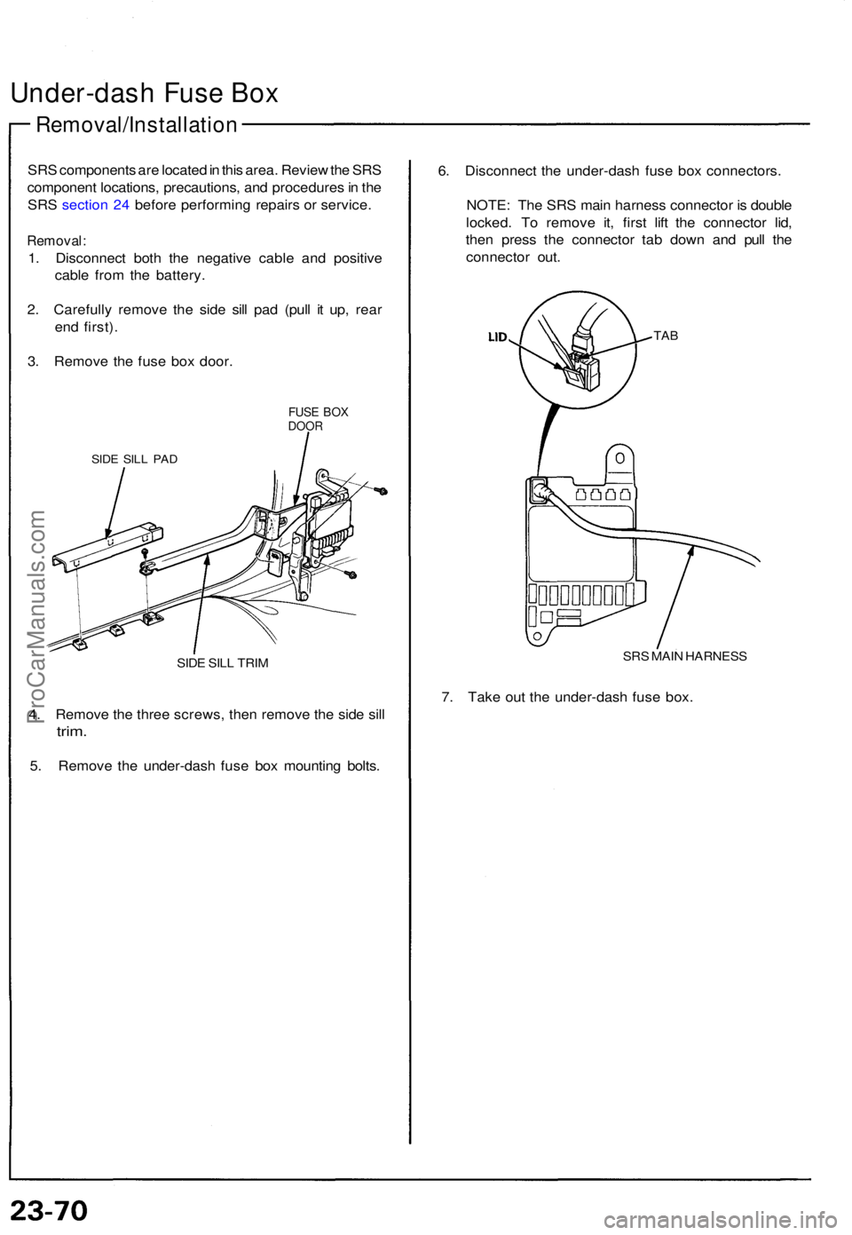
Under-dash Fus e Bo x
Removal/Installatio n
SRS component s ar e locate d in thi s area . Revie w th e SR S
componen t locations , precautions , an d procedure s in th e
SR S sectio n 24 befor e performin g repair s o r service .
Removal :
1. Disconnec t bot h th e negativ e cabl e an d positiv e
cabl e fro m th e battery .
2 . Carefull y remov e th e sid e sil l pa d (pul l i t up , rea r
en d first) .
3 . Remov e th e fus e bo x door .
FUSE BO XDOO R
SIDE SIL L PA D
SIDE SIL L TRI M
4. Remov e th e thre e screws , the n remov e th e sid e sil l
trim .
5. Remov e th e under-das h fus e bo x mountin g bolts . 6
. Disconnec t th e under-das h fus e bo x connectors .
NOTE : Th e SR S mai n harnes s connecto r i s doubl e
locked . T o remov e it , firs t lif t th e connecto r lid ,
the n pres s th e connecto r ta b dow n an d pul l th e
connecto r out .
TAB
SR S MAI N HARNES S
7. Tak e ou t th e under-das h fus e box .
ProCarManuals.com
Page 742 of 1640
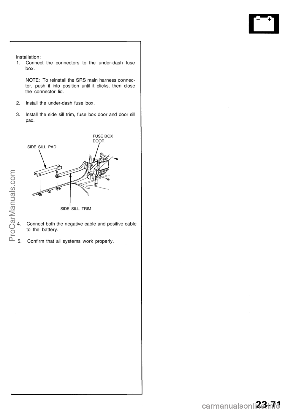
Installation:
1. Connect the connectors to the under-dash fuse
box.
NOTE: To reinstall the SRS main harness connec-
tor, push it into position until it clicks, then close
the connector lid.
2. Install the under-dash fuse box.
3. Install the side sill trim, fuse box door and door sill
pad.
FUSE BOX
DOOR
SIDE SILL PAD
SIDE SILL TRIM
4. Connect both the negative cable and positive cable
to the battery.
5. Confirm that all systems work properly.ProCarManuals.com
Page 743 of 1640
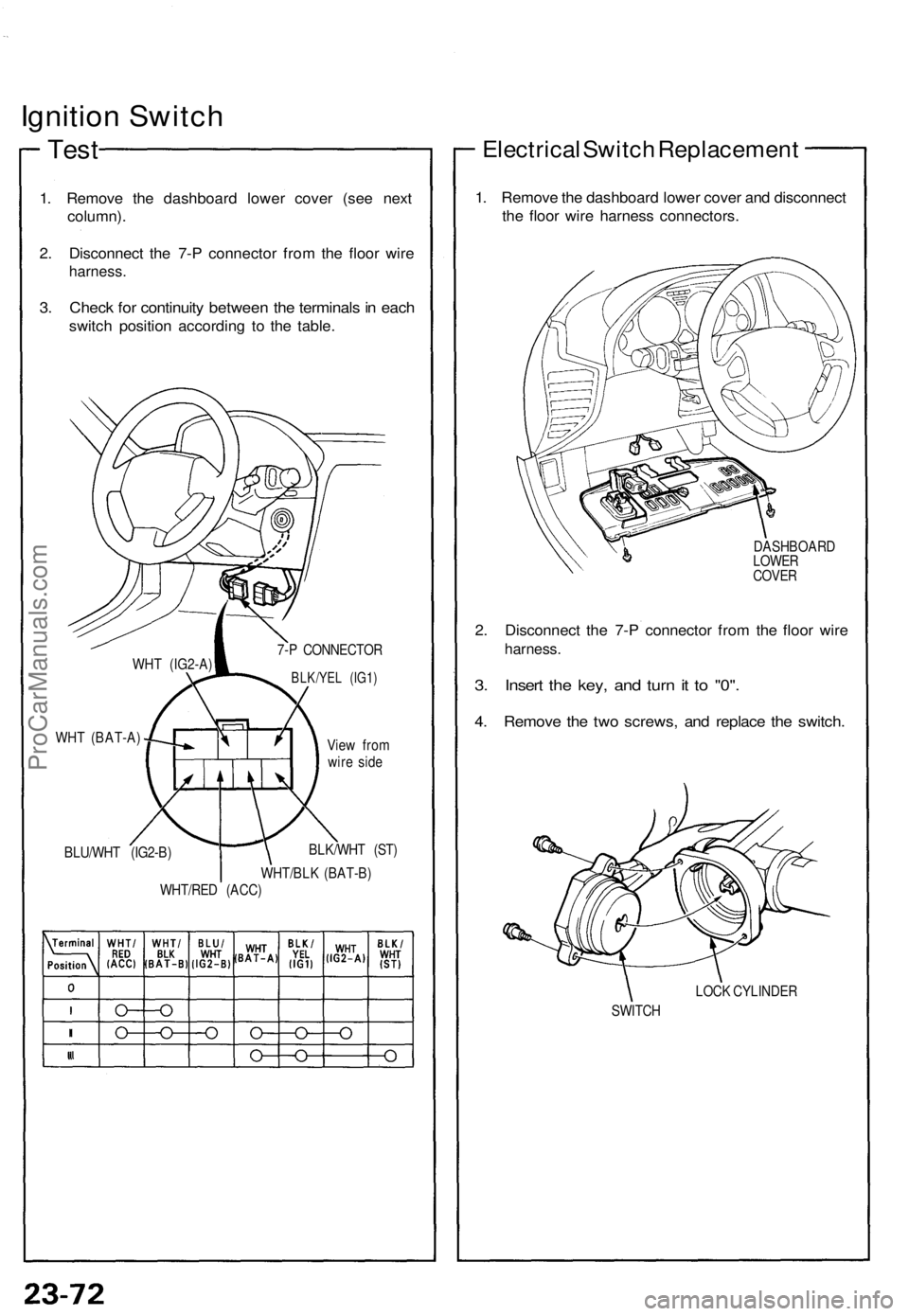
Ignition Switc h
Test
1. Remov e th e dashboar d lowe r cove r (se e nex t
column) .
2 . Disconnec t th e 7- P connecto r fro m th e floo r wir e
harness .
3. Chec k fo r continuit y betwee n th e terminal s in eac h
switc h positio n accordin g t o th e table.
WHT (BAT-A )
BLU/WH T (IG2-B ) Vie
w fro m
wir e sid e
BLK/WH T (ST )
WHT/BL K (BAT-B )
WHT/RE D (ACC )
Electrica l Switc h Replacemen t
1. Remov e th e dashboar d lowe r cove r an d disconnec t
th e floo r wir e harnes s connectors .
DASHBOAR D
LOWE R
COVE R
2. Disconnec t th e 7- P connecto r fro m th e floo r wir e
harness .
3. Inser t th e key , an d tur n it t o "0" .
4. Remov e th e tw o screws , an d replac e th e switch .
LOCK CYLINDE R
SWITC H
WHT
(IG2-A ) 7-
P CONNECTO R
BLK/YEL (IG1)
ProCarManuals.com
Page 744 of 1640
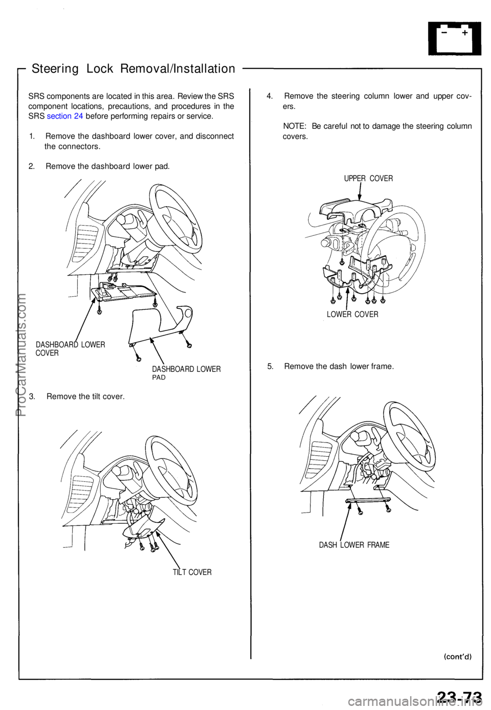
Steering Loc k Removal/Installatio n
SRS component s ar e locate d in thi s area . Revie w th e SR S
componen t locations , precautions , an d procedure s i n th e
SR S sectio n 24 befor e performin g repair s o r service .
1 . Remov e th e dashboar d lowe r cover , an d disconnec t
th e connectors .
2 . Remov e th e dashboar d lowe r pad .
DASHBOAR D LOWE R
COVE R
3. Remov e th e til t cover .
DASHBOAR D LOWE RPAD
TIL T COVE R
4. Remov e th e steerin g colum n lowe r an d uppe r cov -
ers.
NOTE : B e carefu l no t t o damag e th e steerin g colum n
covers.
UPPER COVE R
LOWE R COVE R
5. Remov e th e das h lowe r frame .
DASH LOWE R FRAM E
ProCarManuals.com
Page 745 of 1640
Ignition Switch
Steering Lock Removal/Installation
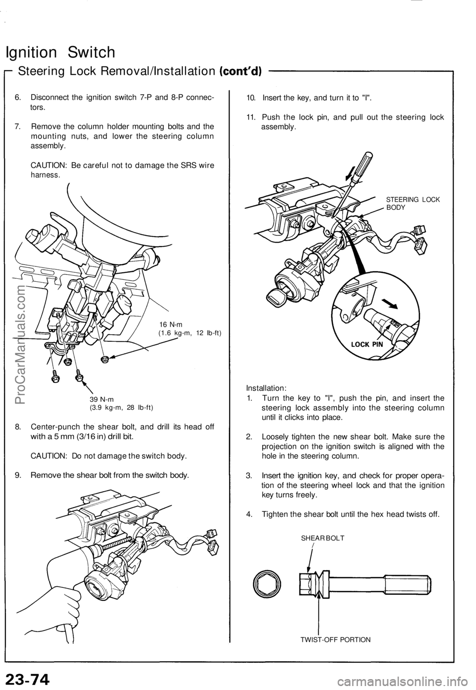
6. Disconnect the ignition switch 7-P and 8-P connec-
tors.
7. Remove the column holder mounting bolts and the
mounting nuts, and lower the steering column
assembly.
CAUTION: Be careful not to damage the SRS wire
harness.
16 N-m
(1.6 kg-m, 12 Ib-ft)
39 N-m
(3.9 kg-m, 28 Ib-ft)
8. Center-punch the shear bolt, and drill its head off
with a 5 mm (3/16 in) drill bit.
CAUTION: Do not damage the switch body.
9. Remove the shear bolt from the switch body.
10. Insert the key, and turn it to "I".
11. Push the lock pin, and pull out the steering lock
assembly.
STEERING LOCK
BODY
Installation:
1. Turn the key to "I", push the pin, and insert the
steering lock assembly into the steering column
until it clicks into place.
2. Loosely tighten the new shear bolt. Make sure the
projection on the ignition switch is aligned with the
hole in the steering column.
3. Insert the ignition key, and check for proper opera-
tion of the steering wheel lock and that the ignition
key turns freely.
4. Tighten the shear bolt until the hex head twists off.
SHEAR BOLT
/
TWIST-OFF PORTIONProCarManuals.com
Page 746 of 1640
Starting System
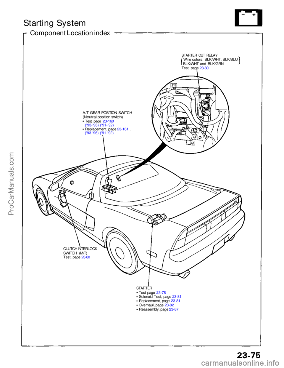
Component Location index
A/T GEAR POSITION SWITCH
(Neutral position switch)
Test page 23-160
('93-'96) ('91-'92)
Replacement, page 23-161 .
('93-'96) ('91-'92)
CLUTCH INTERLOCK
SWITCH (M/T)
Test, page 23-80
STARTER
Test page 23-78Solenoid Test, page 23-81
Replacement, page 23-81
Overhaul, page 23-82 Reassembly. page 23-87
STARTER CUT RELAY
Wire colors: BLK/WHT, BLK/BLU.
BLK/WHT and BLK/GRN
Test, page 23-80ProCarManuals.com
Page 747 of 1640
Starting System
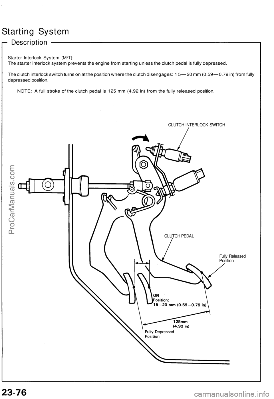
Description
Starter Interlock System (M/T):
The starter interlock system prevents the engine from starting unless the clutch pedal is fully depressed.
The clutch interlock switch turns on at the position where the clutch disengages: 1 5 — 20 mm (0.59 — 0.79 in) from fully
depressed position.
NOTE: A full stroke of the clutch pedal is 125 mm (4.92 in) from the fully released position.
CLUTCH INTERLOCK SWITCH
Fully Released
Position
CLUTCH PEDALProCarManuals.com
Page 748 of 1640
Starting Syste m
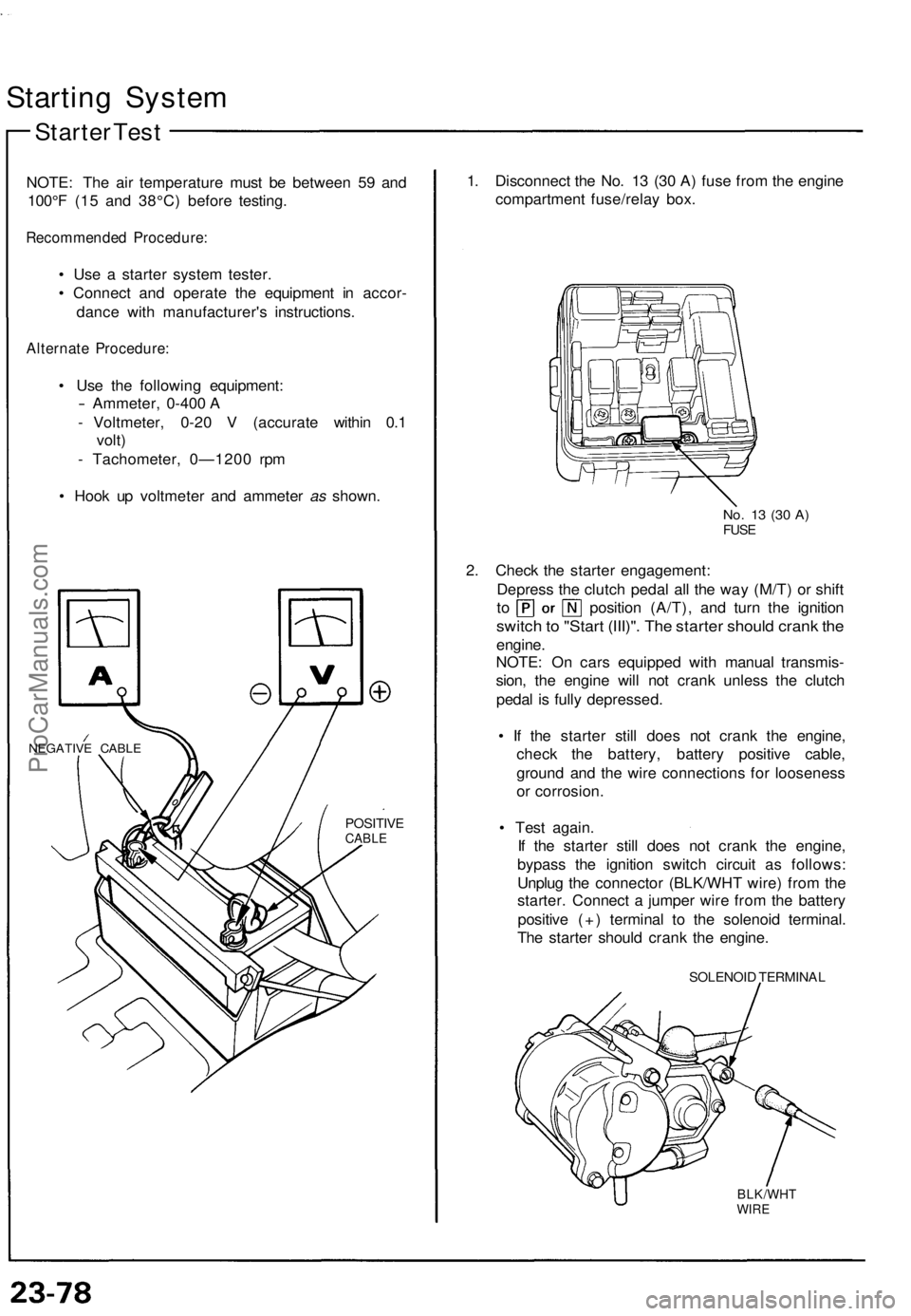
Starter Tes t
NOTE : Th e ai r temperatur e mus t b e betwee n 5 9 an d
100° F (1 5 an d 38°C ) befor e testing .
Recommende d Procedure :
• Us e a starte r syste m tester .
• Connec t an d operat e th e equipmen t i n accor -
danc e wit h manufacturer' s instructions .
Alternate Procedure :
• Us e th e followin g equipment :
- Ammeter, 0-400 A
- Voltmeter , 0-2 0 V (accurat e withi n 0. 1
volt )
- Tachometer , 0—120 0 rp m
• Hoo k u p voltmete r an d ammete r as shown .
NEGATIV E CABL E
POSITIV ECABLE
1. Disconnec t th e No . 1 3 (3 0 A ) fus e fro m th e engin e
compartmen t fuse/rela y box .
No. 1 3 (3 0 A )FUS E
2. Chec k th e starte r engagement :
Depres s th e clutc h peda l al l th e wa y (M/T ) o r shif t
to positio n (A/T) , an d tur n th e ignitio n
switch to "Star t (III)" . Th e starte r shoul d cran k th e
engine .
NOTE : O n car s equippe d wit h manua l transmis -
sion , th e engin e wil l no t cran k unles s th e clutc h
peda l i s full y depressed .
• I f th e starte r stil l doe s no t cran k th e engine ,
chec k th e battery , batter y positiv e cable ,
groun d an d th e wir e connection s fo r loosenes s
o r corrosion .
• Tes t again .
I f th e starte r stil l doe s no t cran k th e engine ,
bypas s th e ignitio n switc h circui t a s follows :
Unplu g th e connecto r (BLK/WH T wire ) fro m th e
starter . Connec t a jumpe r wir e fro m th e batter y
positiv e (+ ) termina l t o th e solenoi d terminal .
Th e starte r shoul d cran k th e engine .
SOLENOI D TERMINA L
BLK/WHTWIRE
ProCarManuals.com
Page 749 of 1640
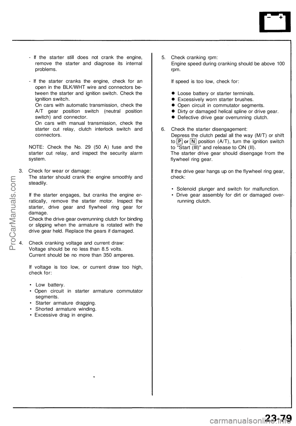
- I f th e starte r stil l doe s no t cran k th e engine ,
remov e th e starte r an d diagnos e it s interna l
problems .
- I f th e starte r crank s th e engine , chec k fo r a n
ope n i n th e BLK/WH T wir e an d connector s be -
twee n th e starte r an d ignitio n switch . Chec k th e
ignitio n switch .
On car s wit h automati c transmission , chec k th e
A/ T gea r positio n switc h (neutra l positio n
switch ) an d connector .
O n car s with manua l transmission , chec k th e
starte r cu t relay , clutc h interloc k switc h an d
connectors .
NOTE : Chec k th e No . 2 9 (5 0 A ) fus e an d th e
starte r cu t relay , an d inspec t th e securit y alar m
system .
3 . Chec k fo r wea r o r damage :
Th e starte r shoul d cran k th e engin e smoothl y an d
steadily .
If th e starte r engages , bu t crank s th e engin e er -
ratically , remov e th e starte r motor . Inspec t th e
starter , driv e gea r an d flywhee l rin g gea r fo r
damage .
Check th e driv e gea r overrunnin g clutc h fo r bindin g
or slippin g whe n th e armatur e i s rotated with th e
driv e gea r held . Replac e th e gear s i f damaged .
4 . Chec k crankin g voltag e an d curren t draw :
Voltag e shoul d b e n o les s tha n 8. 5 volts .
Curren t shoul d b e n o mor e tha n 35 0 amperes .
I f voltag e i s to o low , o r curren t dra w to o high ,
chec k for :
• Lo w battery .
• Ope n circui t i n starte r armatur e commutato r
segments .
• Starte r armatur e dragging .
• Shorte d armatur e winding .
• Excessiv e dra g i n engine . 5
. Chec k crankin g rpm :
Engin e spee d durin g crankin g shoul d b e abov e 10 0
rpm .
If spee d i s to o low , chec k for :
Loos e batter y o r starte r terminals .
Excessivel y wor n starte r brushes .
Ope n circui t i n commutato r segments .
Dirt y o r damage d helica l splin e o r driv e gear .
Defectiv e driv e gea r overrunnin g clutch .
6 . Chec k th e starte r disengagement :
Depres s th e clutc h peda l al l th e wa y (M/T ) o r shif t
to positio n (A/T) , tur n th e ignitio n switc h
to "Star t (III) " an d releas e to O N (II) .
The starter drive gea r shoul d disengag e fro m th e
flywhee l rin g gear .
I f th e driv e gea r hang s u p o n th e flywhee l rin g gear ,
check :
• Solenoi d plunge r an d switc h fo r malfunction .
• Driv e gea r assembl y fo r dir t o r damage d over -
runnin g clutch .
ProCarManuals.com
Page 750 of 1640
Starting Syste m
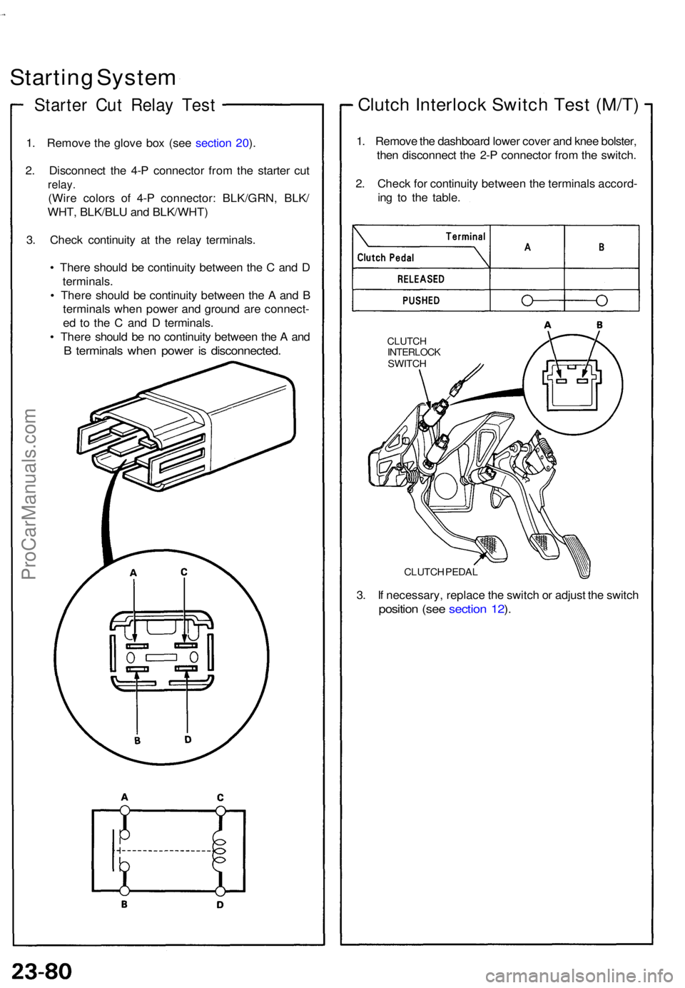
Starte r Cu t Rela y Tes t
1. Remov e th e glov e bo x (se e sectio n 20 ).
2 . Disconnec t th e 4- P connecto r fro m th e starte r cu t
relay .
(Wire color s of 4- P connector : BLK/GRN , BLK /
WHT , BLK/BL U an d BLK/WHT )
3 . Chec k continuit y a t th e rela y terminals .
• Ther e shoul d b e continuit y betwee n th e C an d D
terminals .
• Ther e shoul d b e continuit y betwee n th e A an d B
terminal s whe n powe r an d groun d ar e connect -
e d t o th e C an d D terminals .
• Ther e shoul d b e n o continuit y betwee n th e A an d
B terminal s whe n powe r i s disconnected .
Clutch Interloc k Switc h Tes t (M/T )
1. Remov e th e dashboar d lowe r cove r an d kne e bolster ,
the n disconnec t th e 2- P connecto r fro m th e switch .
2 . Chec k fo r continuit y betwee n th e terminal s accord -
in g t o th e table .
CLUTC HINTERLOC KSWITCH
CLUTC H PEDA L
3. I f necessary , replac e th e switc h o r adjus t th e switc h
positio n (se e sectio n 12 ).
ProCarManuals.com