ACURA NSX 1991 Service Manual PDF
Manufacturer: ACURA, Model Year: 1991, Model line: NSX, Model: ACURA NSX 1991Pages: 1640, PDF Size: 60.48 MB
Page 71 of 1640
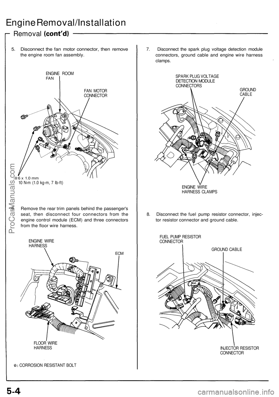
Engine Removal/Installatio n
Removal
5. Disconnec t th e fa n moto r connector , the n remov e
the engin e roo m fa n assembly .
ENGINE ROO MFAN
FAN MOTO R
CONNECTO R
6 x 1. 0 m m10 N- m (1. 0 kg-m , 7 Ib-ft )
6. Remov e th e rea r tri m panel s behin d th e passenger' s
seat , the n disconnec t fou r connector s fro m th e
engin e contro l modul e (ECM ) an d thre e connector s
fro m th e floo r wir e harness .
ENGINE WIR E
HARNES S
ECM
FLOO R WIR E
HARNES S
CORROSIO N RESISTAN T BOL T
7. Disconnec t th e spar k plu g voltag e detectio n modul e
connectors , ground cable an d engin e wir e harnes s
clamps .
SPARK PLU G VOLTAG EDETECTIO N MODUL ECONNECTOR S
GROUND
CABLE
ENGIN E WIR E
HARNES S CLAMP S
8. Disconnec t th e fue l pum p resisto r connector , injec -
to r resisto r connecto r an d groun d cable .
FUEL PUM P RESISTO R
CONNECTO R
GROUND CABL E
INJECTO R RESISTO R
CONNECTO R
ProCarManuals.com
Page 72 of 1640
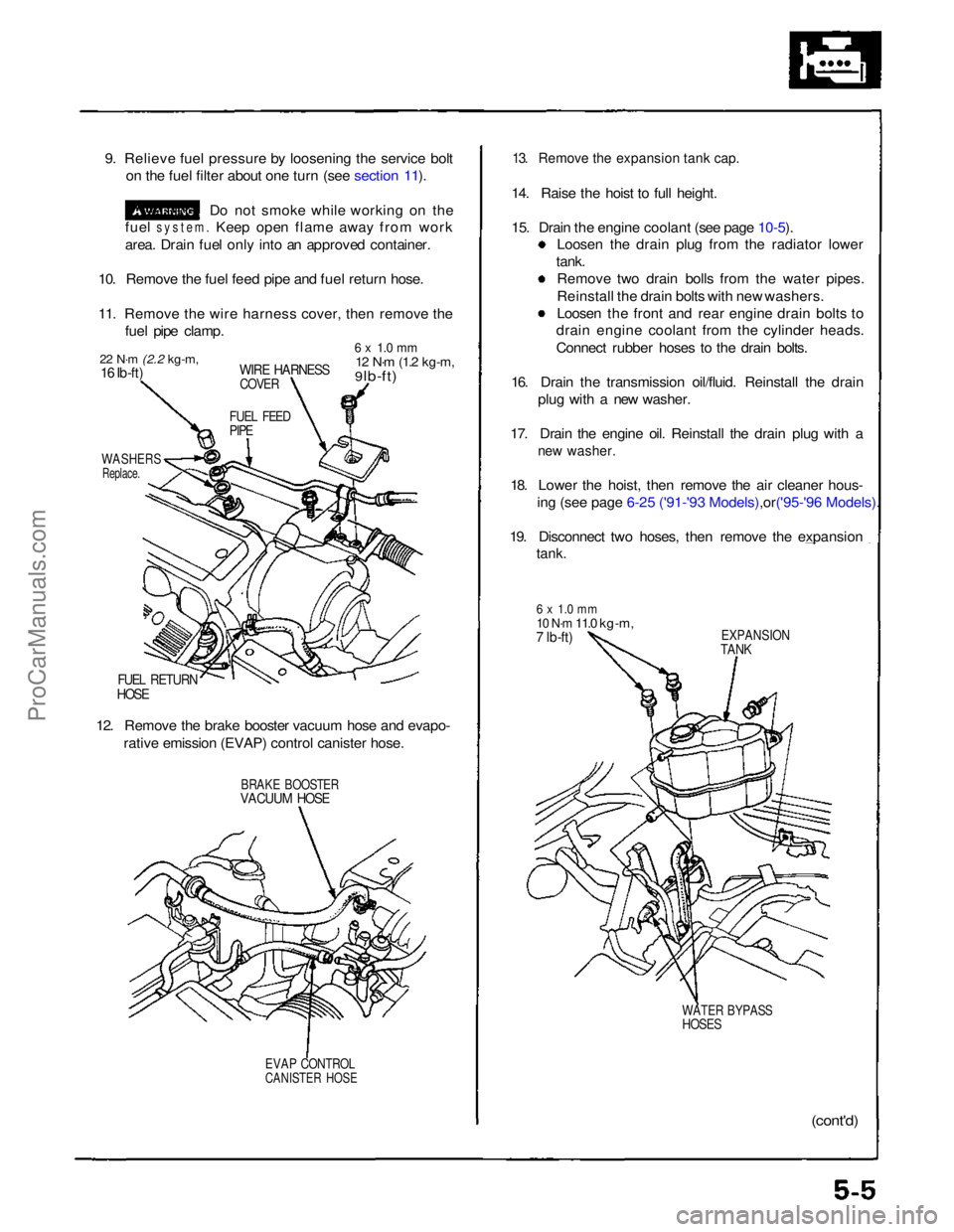
9. Relieve fuel pressure by loosening the service bolt
on the fuel filter about one turn (see section 11).
Do not smoke while working on the
fuel
system.
Keep open flame away from work
area. Drain fuel only into an approved container.
10. Remove the fuel feed pipe and fuel return hose.
11. Remove the wire harness cover, then remove the fuel pipe clamp.
22 N·m
(2.2 kg-m,
16 Ib-ft)
WIRE HARNESS
COVER
6 x 1.0 mm
12 N·m
(1.2 kg-m,
9 lb-ft)
FUEL FEED
PIPE
WASHERS
Replace.
FUEL RETURN
HOSE
12. Remove the brake booster vacuum hose and evapo- rative emission (EVAP) control canister hose.
BRAKE BOOSTER
VACUUM HOSE
EVAP CONTROL
CANISTER HOSE
13. Remove the expansion tank cap.
14. Raise the hoist to full height.
15. Drain the engine coolant (see page
10-5).
Loosen the drain plug from the radiator lower
tank. Remove two drain bolls from the water pipes.
Reinstall the drain bolts with new washers.
Loosen the front and rear engine drain bolts to
drain engine coolant from the cylinder heads.
Connect rubber hoses to the drain bolts.
16. Drain the transmission oil/fluid. Reinstall the drain plug with a new washer.
17. Drain the engine oil. Reinstall the drain plug with a
new washer.
18. Lower the hoist, then remove the air cleaner hous-
ing (see page 6-25 ('91-'93 Mode ls),or('95-'96 Models).
19. Disconnect two hoses, then remove the expansion
tank.
6 x 1.0 mm
10 N·m
11.0 kg-m,
7 lb-ft)
EXPANSION
TANK
WATER BYPASS
HOSES
(cont'd)ProCarManuals.com
Page 73 of 1640
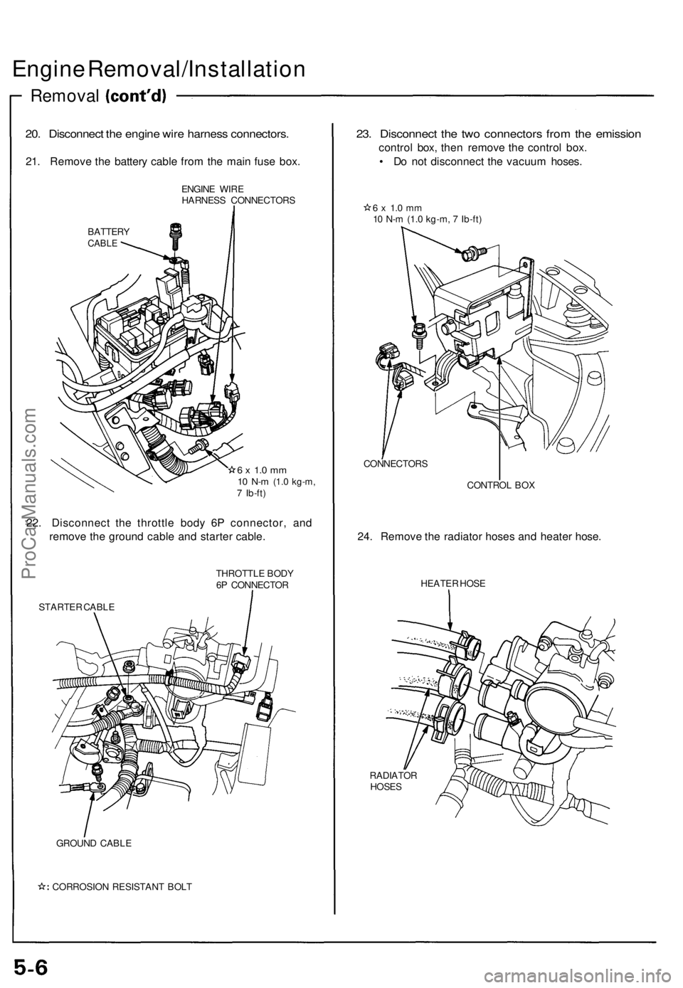
Engine Removal/Installation
Removal
20. Disconnect the engine wire harness connectors.
21. Remove the battery cable from the main fuse box.
ENGINE WIRE
HARNESS CONNECTORS
BATTERY
CABLE
6 x 1.0 mm
10 N-m
(1.0 kg-m,
7 Ib-ft)
22. Disconnect the throttle body 6P connector, and
remove the ground cable and starter cable.
STARTER CABLE
THROTTLE BODY
6P CONNECTOR
GROUND CABLE
CORROSION RESISTANT BOLT
23. Disconnect the two connectors from the emission
control box, then remove the control box.
• Do not disconnect the vacuum hoses.
6 x 1.0 mm
10 N-m (1.0 kg-m, 7 Ib-ft)
CONNECTORS
CONTROL BOX
24. Remove the radiator hoses and heater hose.
HEATER HOSE
RADIATOR
HOSESProCarManuals.com
Page 74 of 1640
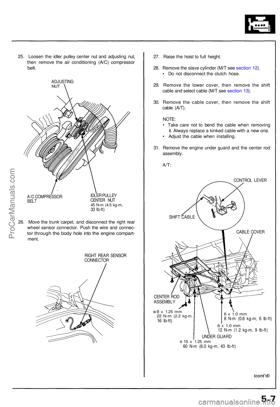
25. Loose n th e idle r pulle y cente r nu t an d adjustin g nut ,
the n remov e th e ai r conditionin g (A/C ) compresso r
belt.
ADJUSTIN GNUT
A/C COMPRESSO RBELT
IDLE R PULLE Y
CENTE R NU T
45 N- m (4. 5 kg-m ,33 Ib-ft )
26. Mov e th e trun k carpet , an d disconnec t th e righ t rea r
whee l senso r connector . Pus h th e wir e an d connec -
tor throug h th e bod y hol e int o th e engin e compart -
ment.
RIGH T REA R SENSO R
CONNECTO R
27. Rais e th e hois t t o ful l height .
28 . Remov e th e slav e cylinde r (M/ T se e sectio n 12 ).
• D o no t disconnec t th e clutc h hose .
29 . Remov e th e lowe r cover , the n remov e th e shif t
cabl e an d selec t cabl e (M/ T se e sectio n 13 ).
30 . Remov e th e cabl e cover , the n remov e th e shif t
cabl e (A/T) .
NOTE :
• Tak e car e no t t o ben d th e cabl e whe n removin g
it . Alway s replac e a kinke d cabl e wit h a ne w one .
• Adjus t th e cabl e whe n installing .
31 . Remov e th e engin e unde r guar d an d th e cente r ro d
assembly .
A/T:
CONTRO L LEVE R
CENTE R RO D
ASSEMBL Y
8 x 1.2 5 mm22 N- m (2. 2 kg-m ,16 Ib-ft )
6 x 1. 0 m m8 N- m (0. 8 kg-m , 6 Ib-ft )
6 x 1. 0 m m12 N- m (1. 2 kg-m , 9 Ib-ft )
UNDE R GUAR D
10 x 1.2 5 mm60 N- m (6. 0 kg-m , 4 3 Ib-ft )
SHIF
T CABL E
CABLE COVE R
ProCarManuals.com
Page 75 of 1640
Engine Removal/Installatio n
Removal
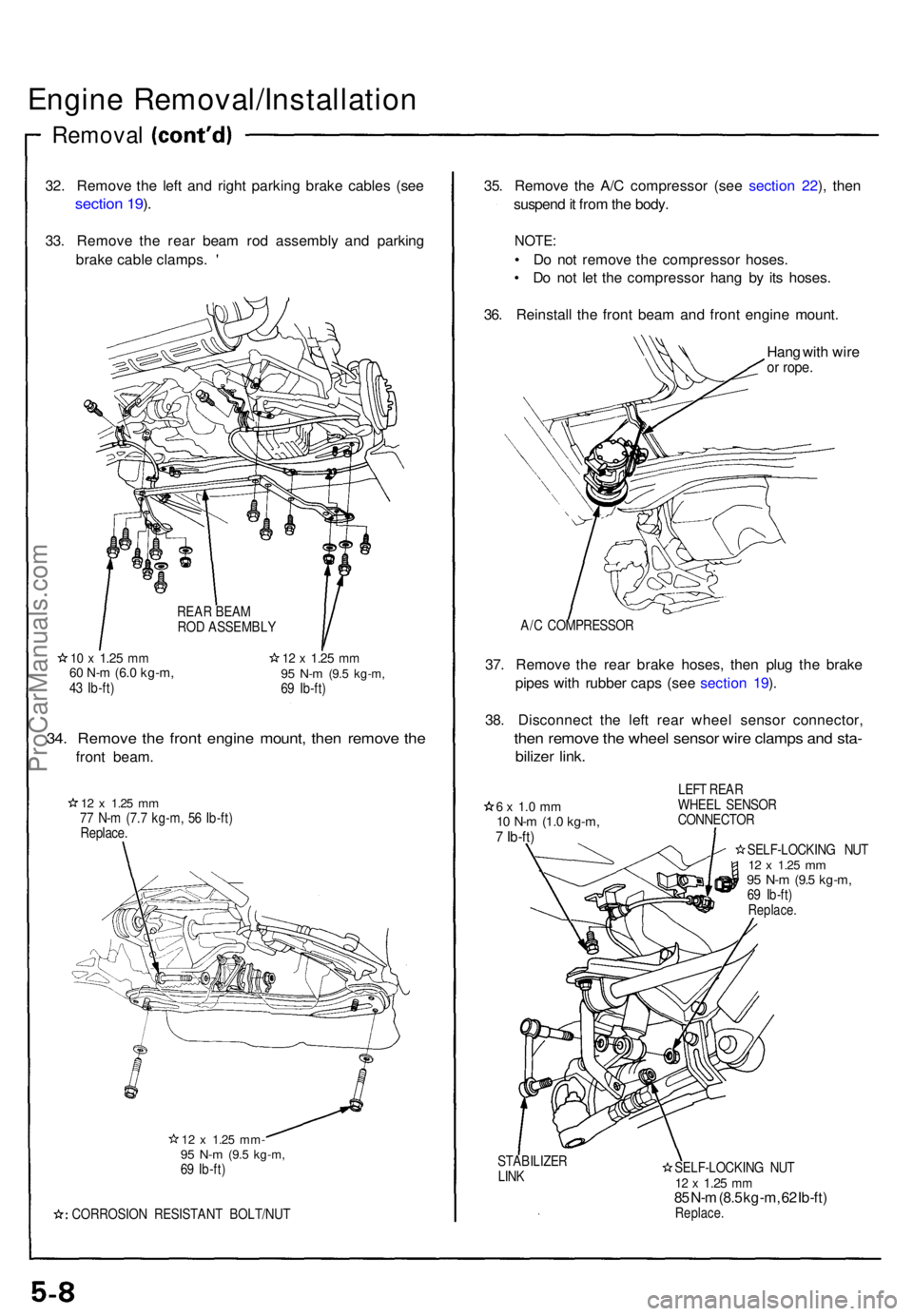
32. Remov e th e lef t an d righ t parkin g brak e cable s (se e
sectio n 19 ).
33 . Remov e th e rea r bea m ro d assembl y an d parkin g
brak e cabl e clamps . '
1 0 x 1.2 5 mm60 N- m (6. 0 kg-m ,43 Ib-ft )
12 x 1.2 5 mm95 N- m (9. 5 kg-m ,69 Ib-ft )
34. Remov e th e fron t engin e mount , the n remov e th e
fron t beam .
12 x 1.2 5 mm77 N- m (7. 7 kg-m , 5 6 Ib-ft )
Replace .
12 x 1.2 5 mm -95 N- m (9. 5 kg-m ,69 Ib-ft )
CORROSIO N RESISTAN T BOLT/NU T
35. Remov e th e A/ C compresso r (se e sectio n 22 ), the n
suspen d it fro m th e body .
NOTE :
• D o no t remov e th e compresso r hoses .
• D o no t le t th e compresso r han g b y it s hoses .
36 . Reinstal l th e fron t bea m an d fron t engin e mount .
Han g wit h wir e
or rope .
A/C COMPRESSO R
37. Remov e th e rea r brak e hoses , the n plu g th e brak e
pipe s wit h rubbe r cap s (se e sectio n 19 ).
38 . Disconnec t th e lef t rea r whee l senso r connector ,
then remov e th e whee l senso r wir e clamp s an d sta -
bilize r link .
6 x 1. 0 m m10 N- m (1. 0 kg-m ,7 Ib-ft )
LEFT REA R
WHEE L SENSO R
CONNECTO R
SELF-LOCKIN G NU T
12 x 1.2 5 mm95 N- m (9. 5 kg-m ,69 Ib-ft )Replace .
STABILIZE R
LIN K SELF-LOCKIN
G NU T
12 x 1.2 5 mm85 N- m (8. 5 kg-m , 6 2 Ib-ft )Replace .
REAR BEA M
RO D ASSEMBL Y
ProCarManuals.com
Page 76 of 1640
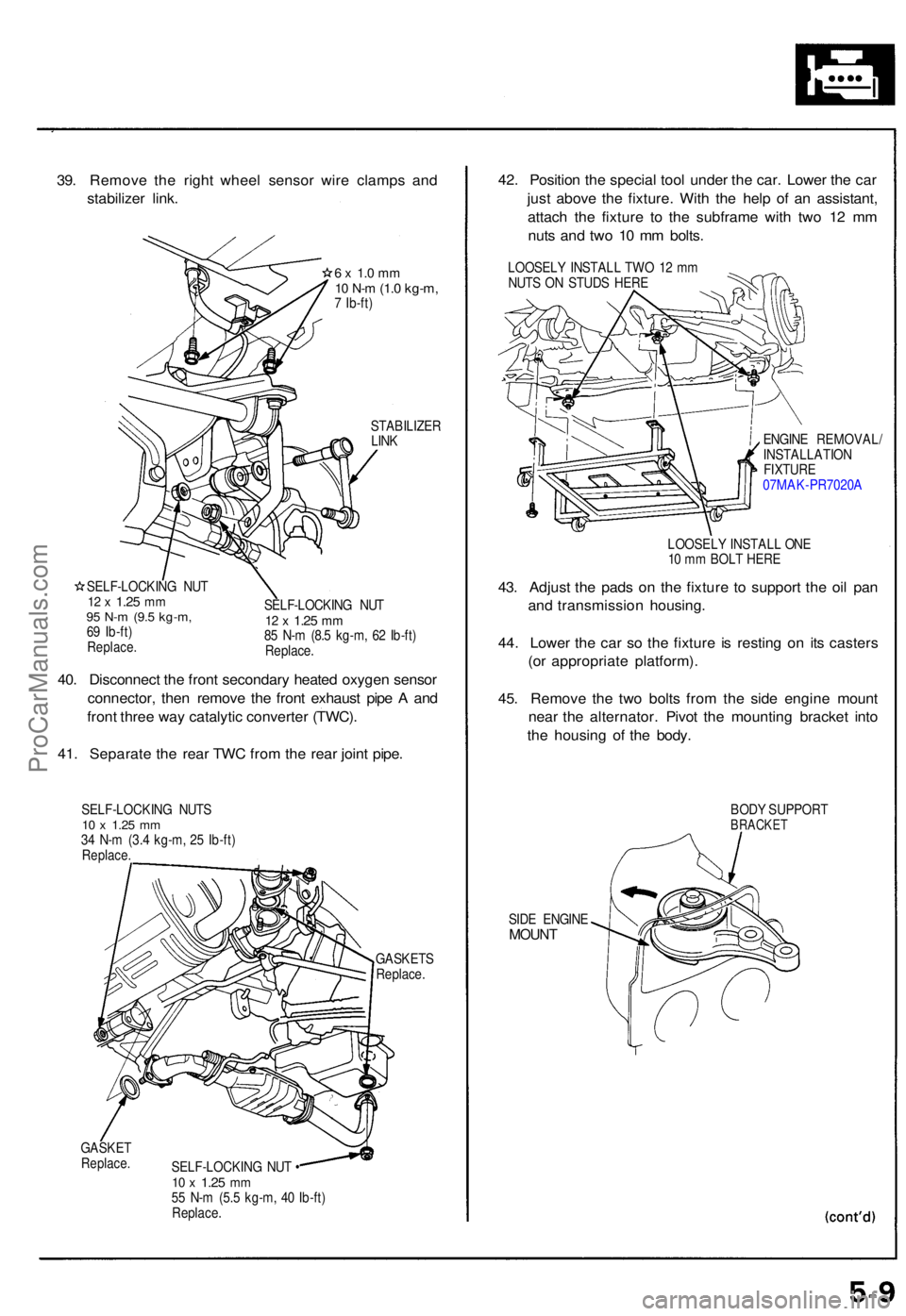
39. Remov e th e righ t whee l senso r wir e clamp s an d
stabilize r link .
6 x 1. 0 m m10 N- m (1. 0 kg-m ,7 Ib-ft )
STABILIZE RLINK
SELF-LOCKIN G NU T
12 x 1.2 5 mm95 N- m (9. 5 kg-m ,69 Ib-ft )Replace .
SELF-LOCKIN G NU T12 x 1.2 5 mm85 N- m (8. 5 kg-m , 6 2 Ib-ft )
Replace .
40. Disconnec t th e fron t secondar y heate d oxyge n senso r
connector , the n remov e th e fron t exhaus t pip e A an d
fron t thre e wa y catalyti c converte r (TWC) .
41 . Separat e th e rea r TW C fro m th e rea r join t pipe .
SELF-LOCKIN G NUT S10 x 1.2 5 mm34 N- m (3. 4 kg-m , 2 5 Ib-ft )Replace .
GASKET SReplace.
GASKETReplace .SELF-LOCKIN G NU T •10 x 1.2 5 mm55 N- m (5. 5 kg-m , 4 0 Ib-ft )Replace .
42. Positio n th e specia l too l unde r th e car . Lowe r th e ca r
jus t abov e th e fixture . Wit h th e hel p o f a n assistant ,
attac h th e fixtur e t o th e subfram e wit h tw o 1 2 m m
nut s an d tw o 1 0 m m bolts .
LOOSEL Y INSTAL L TW O 1 2 m m
NUT S O N STUD S HER E
ENGINE REMOVAL /
INSTALLATIO N
FIXTURE07MAK-PR7020 A
LOOSEL Y INSTAL L ON E
1 0 m m BOL T HER E
43. Adjus t th e pad s o n th e fixtur e t o suppor t th e oi l pa n
an d transmissio n housing .
44 . Lowe r th e ca r s o th e fixtur e i s restin g o n it s caster s
(o r appropriat e platform) .
45 . Remov e th e tw o bolt s fro m th e sid e engin e moun t
nea r th e alternator . Pivo t th e mountin g bracke t int o
th e housin g o f th e body .
BODY SUPPOR TBRACKET
SIDE ENGIN EMOUNT
ProCarManuals.com
Page 77 of 1640
Engine Removal/Installatio n
Removal
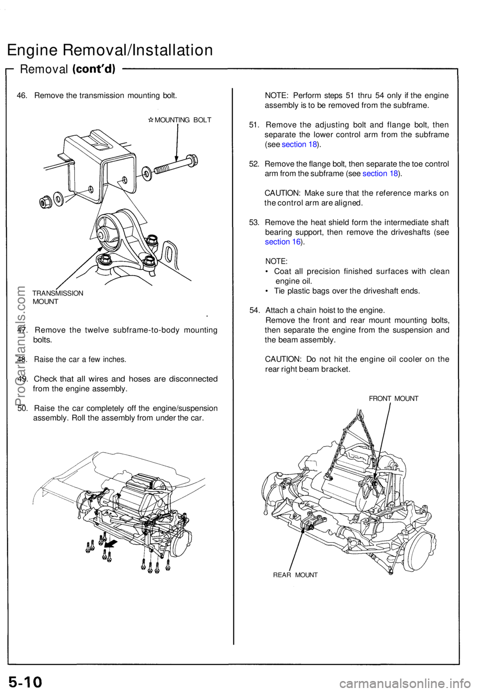
46. Remov e th e transmissio n mountin g bolt .
MOUNTIN G BOL T
TRANSMISSIO NMOUNT
47. Remov e th e twelv e subframe-to-bod y mountin g
bolts.
48. Rais e th e ca r a fe w inches .
49. Chec k tha t al l wire s an d hose s ar e disconnecte d
from th e engin e assembly .
50 . Rais e th e ca r completel y of f th e engine/suspensio n
assembly . Rol l th e assembl y fro m unde r th e car . NOTE
: Perfor m step s 5 1 thr u 5 4 onl y i f th e engin e
assembl y is t o b e remove d fro m th e subframe .
51 . Remov e th e adjustin g bol t an d flang e bolt , the n
separat e th e lowe r contro l ar m fro m th e subfram e
(se e sectio n 18 ).
52 . Remov e th e flang e bolt , the n separat e th e to e contro l
ar m fro m th e subfram e (se e sectio n 18 ).
CAUTION : Mak e sur e tha t th e referenc e mark s o n
th e contro l ar m ar e aligned .
53 . Remov e th e hea t shiel d for m th e intermediat e shaf t
bearin g support , the n remov e th e driveshaft s (se e
sectio n 16 ).
NOTE :
• Coa t al l precisio n finishe d surface s wit h clea n
engin e oil .
• Ti e plasti c bag s ove r th e driveshaf t ends .
54 . Attac h a chai n hois t t o th e engine .
Remov e th e fron t an d rea r moun t mountin g bolts ,
the n separat e th e engine from th e suspensio n an d
th e bea m assembly .
CAUTION : D o no t hi t th e engin e oi l coole r o n th e
rea r righ t bea m bracket .
FRONT MOUN T
REAR MOUN T
ProCarManuals.com
Page 78 of 1640
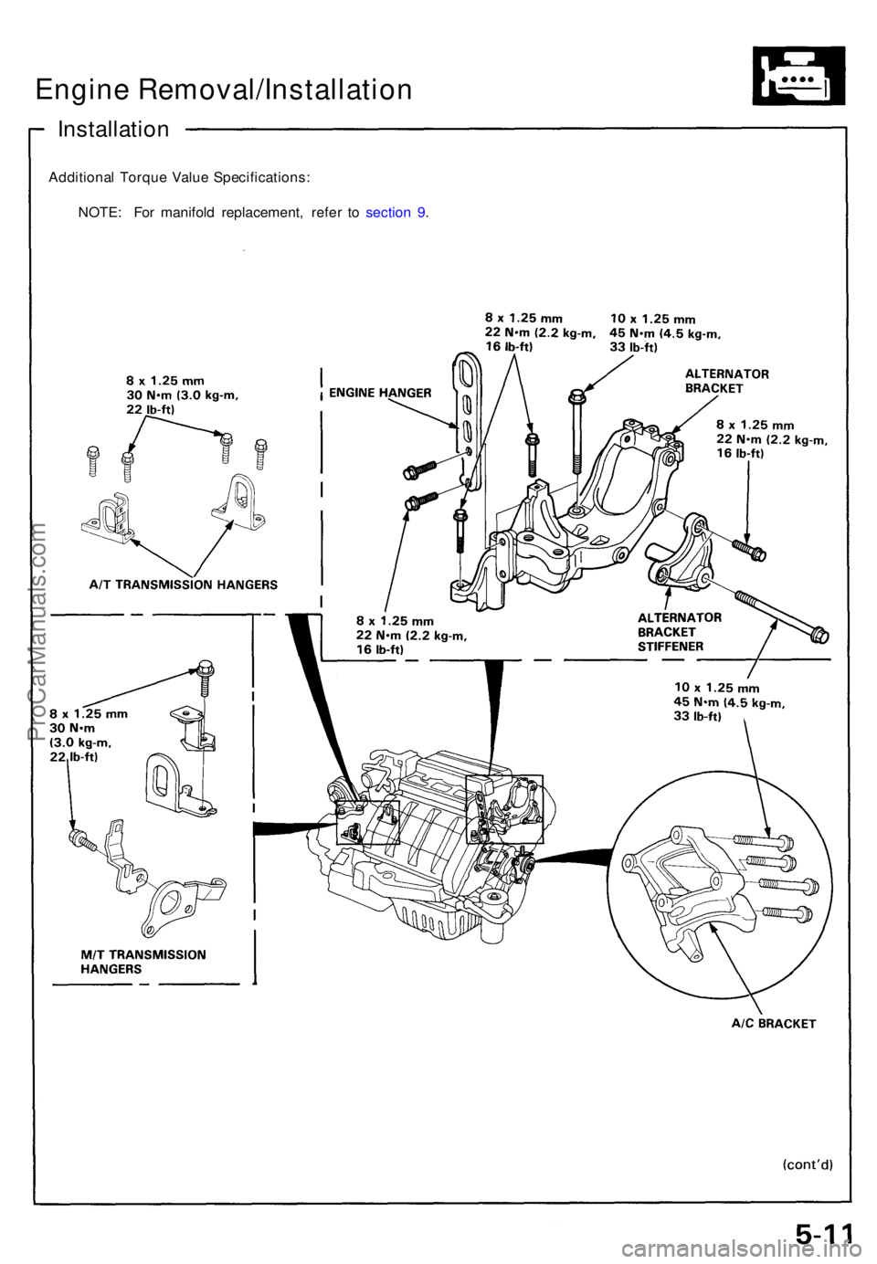
Installation
Additional Torqu e Valu e Specifications :
NOTE : Fo r manifol d replacement , refe r t o sectio n 9 .
Engine Removal/Installation
ProCarManuals.com
Page 79 of 1640
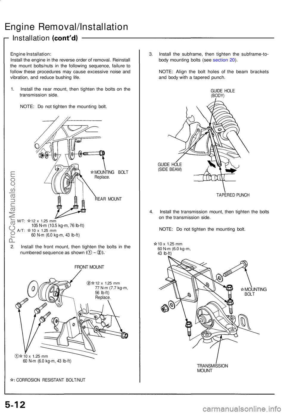
Engine Removal/Installatio n
Installation
Engine Installation :
Instal l th e engin e in th e revers e orde r o f removal . Reinstal l
th e moun t bolts/nut s i n th e followin g sequence , failur e t o
follo w thes e procedure s ma y caus e excessiv e nois e an d
vibration , an d reduc e bushin g life .
1 . Instal l th e rea r mount , the n tighte n th e bolt s o n th e
transmissio n side .
NOTE : D o no t tighte n th e mountin g bolt .
MOUNTIN G BOL T
Replace .
REA R MOUN T
M/T: 1 2 x 1.2 5 mm105 N- m (10. 5 kg-m , 7 6 Ib-ft )A/T: 1 0 x 1.2 5 mm60 N- m (6. 0 kg-m , 4 3 Ib-ft )
2. Instal l th e fron t mount , the n tighte n th e bolt s i n th e
numbere d sequenc e a s show n
FRONT MOUN T
12 x 1.2 5 mm77 N- m (7. 7 kg-m ,56 Ib-ft )Replace .
10 x 1.2 5 mm60 N- m (6. 0 kg-m , 4 3 Ib-ft )
CORROSIO N RESISTAN T BOLT/NU T
3. Instal l th e subframe , the n tighte n th e subframe-to -
bod y mountin g bolt s (se e sectio n 20 ).
NOTE : Alig n th e bol t hole s o f th e bea m bracket s
an d bod y wit h a tapere d punch .
GUIDE HOL E(BODY )
GUIDE HOL E
(SID E BEAM )
TAPERED PUNC H
4. Instal l th e transmissio n mount , the n tighte n th e bolt s
o n th e transmissio n side .
NOTE : D o no t tighte n th e mountin g bolt .
10 x 1.2 5 mm60 N- m (6. 0 kg-m ,43 Ib-ft )
MOUNTIN GBOLT
TRANSMISSIO NMOUNT
ProCarManuals.com
Page 80 of 1640
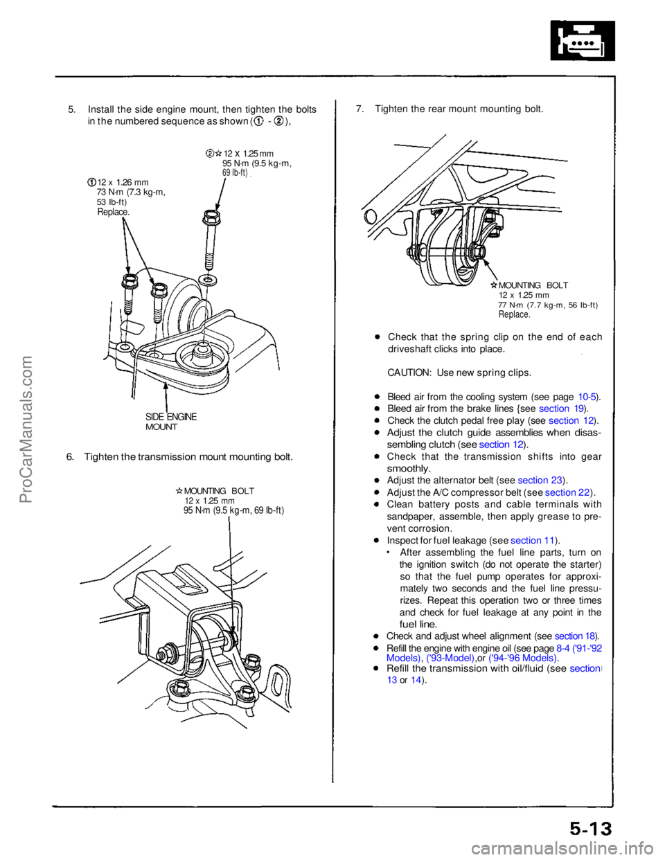
5. Install the side engine mount, then tighten the bolts
in the numbered sequence as shown ( - ),
12 x
1.26
mm
73 N·m
(7.3 kg-m,
53 Ib-ft)
Replace.
12 x
1.25
mm
95 N·m
(9.5 kg-m,
69 Ib-ft)
SIDE ENGINE
MOUNT
6. Tighten the transmission mount mounting bolt.
MOUNTING BOLT
12 x
1.25
mm
95 N·m (9.5 kg-m, 69 Ib-ft)
7. Tighten the rear mount mounting bolt.
MOUNTING BOLT
12 x
1.25
mm
77 N·m (7.7 kg-m, 56 Ib-ft)
Replace.
Check that the spring clip on the end of each
driveshaft clicks into place.
CAUTION: Use new spring clips.
Bleed air from the cooling system (see page 10-5).
Bleed air from the brake lines {see section 19).
Check the clutch pedal free play (see section 12).
Adjust the clutch guide assemblies when disas-
sembling clutch (see section 12).
Check that the transmission shifts into gear
smoothly.
Adjust the alternator belt (see section 23).
Adjust the A/C compressor belt (see section 22).
Clean battery posts and cable terminals with
sandpaper, assemble, then apply grease to pre-
vent corrosion.
Inspect for fuel leakage (see section 11). After assembling the fuel line parts, turn on
the ignition switch (do not operate the starter) so that the fuel pump operates for approxi-
mately two seconds and the fuel line pressu-
rizes. Repeat this operation two or three times
and check for fuel leakage at any point in the
fuel line.
Check and adjust wheel alignment (see section 18).
Refill the engine with engine oil (see page 8-4 ('91-'92
Models), ('93-Model),or ('94-'96 Models).
Refill the transmission with oil/fluid (see section
13 or
14).ProCarManuals.com