ACURA NSX 1991 Service Repair Manual
Manufacturer: ACURA, Model Year: 1991, Model line: NSX, Model: ACURA NSX 1991Pages: 1640, PDF Size: 60.48 MB
Page 111 of 1640
Valves, Valv e Spring s an d Valv e Seal s
Replacemen t
NOTE: Identif y valve s an d valv e spring s a s the y ar e re -
move d s o tha t eac h ite m ca n b e reinstalle d in it s origina l
position .
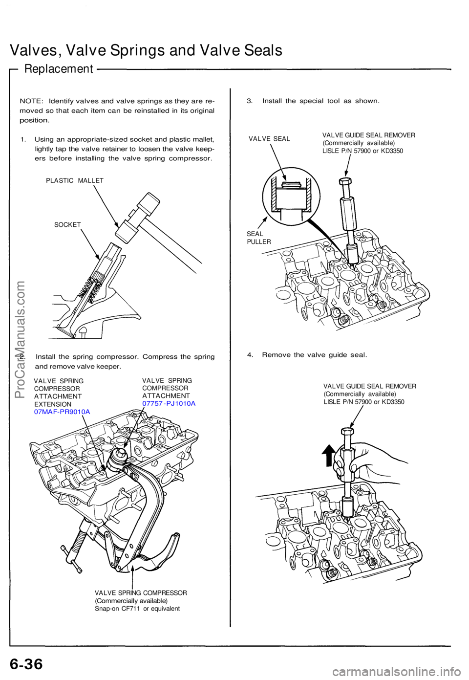
1. Usin g a n appropriate-size d socke t an d plasti c mallet ,
lightl y ta p th e valv e retaine r t o loose n th e valv e keep -
er s befor e installin g th e valv e sprin g compressor .
PLASTIC MALLE T
SOCKE T
2. Instal l th e sprin g compressor . Compres s th e sprin g
an d remov e valv e keeper .
VALVE SPRIN G
COMPRESSO R
ATTACHMENTEXTENSION07MAF-PR9010 A
VALVE SPRIN G
COMPRESSO R
ATTACHMENT07757 - PJ1010 A
VALVE SPRIN G COMPRESSO R(Commercially available )Snap-on CF71 1 o r equivalen t
3. Instal l th e specia l too l a s shown .
VALVE SEA L VALV
E GUID E SEA L REMOVE R
(Commerciall y available )
LISL E P/ N 5790 0 o r KD335 0
SEALPULLE R
4. Remov e th e valv e guid e seal .
VALV E GUID E SEA L REMOVE R
(Commerciall y available )
LISL E P/ N 5790 0 o r KD335 0
ProCarManuals.com
Page 112 of 1640
ProCarManuals.com
Page 113 of 1640
Cylinder Head s
Warpag e
NOTE: I f camshaft-to-holde r oi l clearance s (se e pag e 6-34 )
ar e no t withi n specification , th e cylinde r hea d canno t b e
resurfaced .
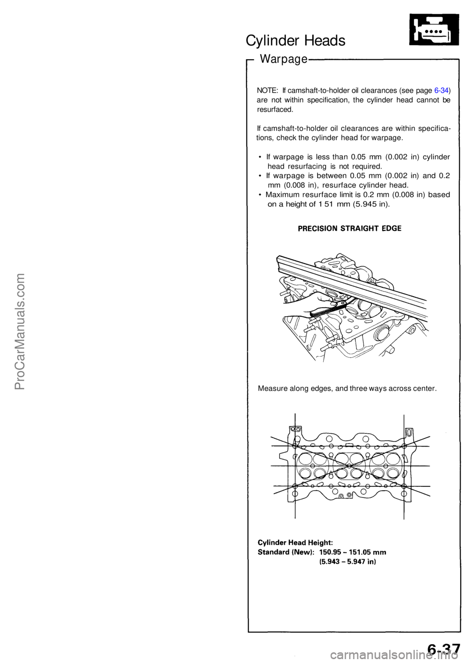
If camshaft-to-holde r oi l clearance s ar e withi n specifica -
tions , chec k th e cylinde r hea d fo r warpage .
• I f warpag e i s les s tha n 0.0 5 m m (0.00 2 in ) cylinde r
head resurfacin g i s no t required .
• I f warpag e i s betwee n 0.0 5 m m (0.00 2 in ) an d 0. 2
mm (0.00 8 in) , resurfac e cylinde r head .
• Maximu m resurfac e limi t i s 0. 2 m m (0.00 8 in ) base d
on a heigh t o f 1 51 m m (5.94 5 in) .
Measur e alon g edges , an d thre e way s acros s center .
ProCarManuals.com
Page 114 of 1640
Valve Seat s
Reconditionin g
1. Rene w th e valv e seat s i n th e cylinde r hea d usin g a
valv e sea t grinder .
NOTE : I f guide s ar e wor n (se e pag e 6-39 ), replac e
the m (se e pag e 6-40 ) befor e grindin g th e valv e seats .
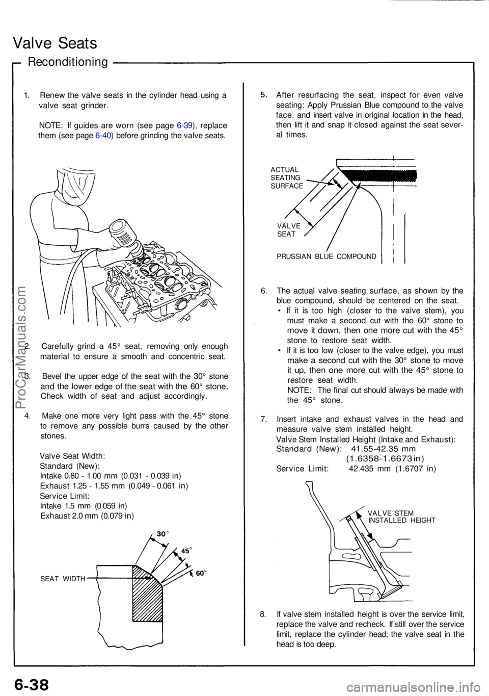
2 . Carefull y grin d a 45 ° seat , removin g onl y enoug h
materia l t o ensur e a smoot h an d concentri c seat .
3 . Beve l th e uppe r edg e o f th e sea t wit h th e 30 ° ston e
and th e lowe r edg e of the sea t wit h th e 60 ° stone .
Check widt h o f sea t an d adjus t accordingly .
4 . Mak e on e mor e ver y ligh t pas s wit h th e 45 ° ston e
t o remov e an y possibl e burr s cause d b y th e othe r
stones .
Valv e Sea t Width :
Standar d (New) :
Intak e 0.8 0 - 1.0 0 m m (0.03 1 - 0.03 9 in )
Exhaus t 1.2 5 - 1.5 5 m m (0.04 9 - 0.06 1 in )
Servic e Limit :
Intak e 1. 5 m m (0.05 9 in )
Exhaus t 2. 0 m m (0.07 9 in )
SEA T WIDT H
After resurfacin g th e seat , inspec t fo r eve n valv e
seating : Appl y Prussia n Blu e compoun d t o th e valv e
face , an d inser t valv e in origina l locatio n in th e head ,
the n lif t i t an d sna p it close d agains t th e sea t sever -
a l times .
ACTUA L
SEATIN G
SURFAC E
VALVESEAT
PRUSSIA N BLU E COMPOUN D
6. Th e actua l valv e seatin g surface , a s show n b y th e
blu e compound , shoul d b e centere d o n th e seat .
• I f i t i s to o hig h (close r t o th e valv e stem) , yo u
mus t mak e a secon d cu t wit h th e 60 ° ston e t o
mov e it down , the n on e mor e cu t wit h th e 45 °
ston e t o restor e sea t width .
• I f i t i s to o lo w (close r t o th e valv e edge) , yo u mus t
make a secon d cu t wit h th e 30 ° ston e t o mov e
it up , the n on e mor e cu t wit h th e 45 ° ston e t o
restor e sea t width .
NOTE : Th e fina l cu t shoul d alway s b e mad e wit h
th e 45 ° stone .
7 . Inser t intak e an d exhaus t valve s i n th e hea d an d
measur e valv e ste m installe d height .
Valv e Ste m Installe d Heigh t (Intak e an d Exhaust) :
Standard (New) : 41.55-42.3 5 m m
(1.6358-1.667 3 in )
Servic e Limit : 42.43 5 m m (1.670 7 in )
VALV E STE M
INSTALLE D HEIGH T
8. I f valv e ste m installe d heigh t i s ove r th e servic e limit ,
replac e th e valv e an d recheck . I f stil l ove r th e servic e
limit , replac e th e cylinde r head ; th e valv e sea t i n th e
hea d is to o deep .
ProCarManuals.com
Page 115 of 1640
Valve Guides
Valve Movement
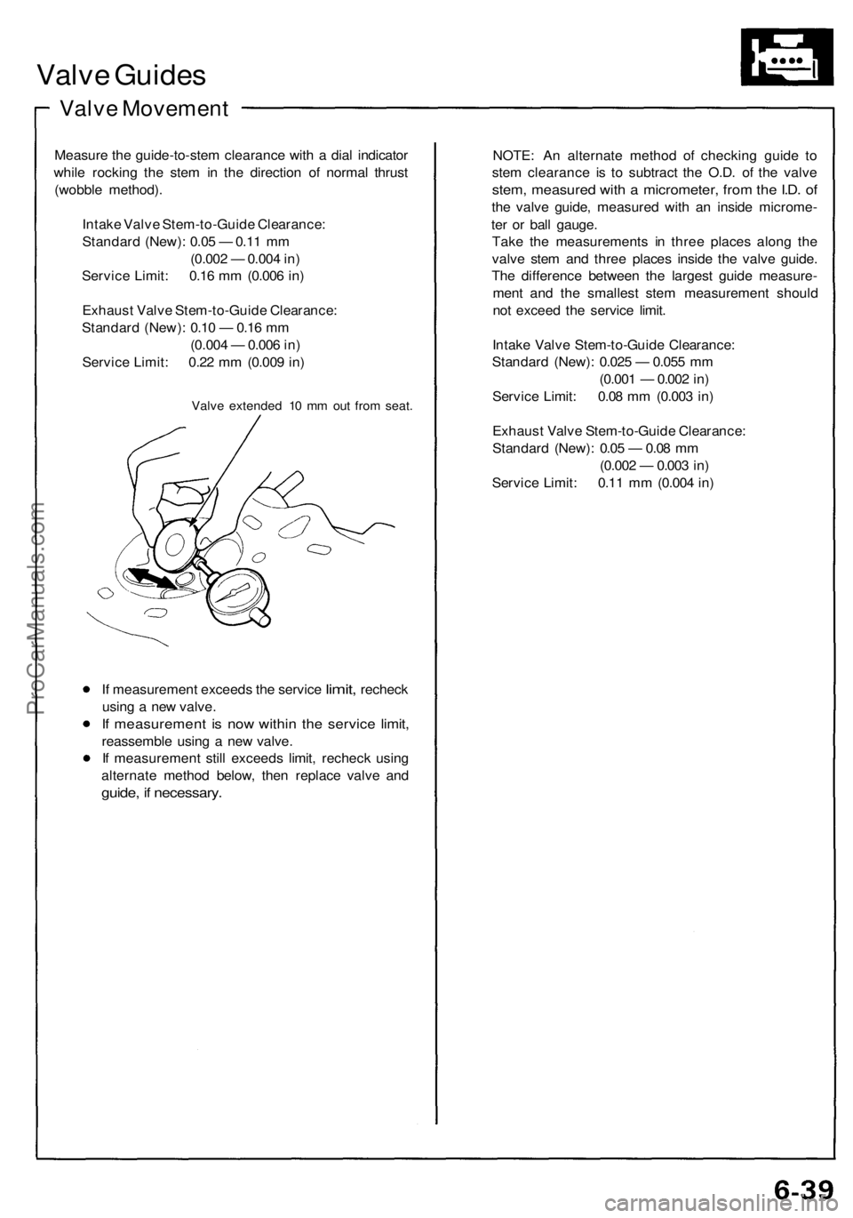
Measure the guide-to-stem clearance with a dial indicator
while rocking the stem in the direction of normal thrust
(wobble method).
Intake Valve Stem-to-Guide Clearance:
Standard (New): 0.05 — 0.11 mm
(0.002 — 0.004 in)
Service Limit: 0.16 mm (0.006 in)
Exhaust Valve Stem-to-Guide Clearance:
Standard (New): 0.10 — 0.16 mm
(0.004 — 0.006 in)
Service Limit: 0.22 mm (0.009 in)
Valve extended 10 mm out from seat.
If
measurement exceeds
the
service
limit,
recheck
using a new valve.
If measurement is now within the service limit,
reassemble using a new valve.
If measurement still exceeds limit, recheck using
alternate method below, then replace valve and
guide, if necessary.
NOTE: An alternate method of checking guide to
stem clearance is to subtract the O.D. of the valve
stem, measured with a micrometer, from the I.D. of
the valve guide, measured with an inside microme-
ter or ball gauge.
Take the measurements in three places along the
valve stem and three places inside the valve guide.
The difference between the largest guide measure-
ment and the smallest stem measurement should
not exceed the service limit.
Intake Valve Stem-to-Guide Clearance:
Standard (New): 0.025 — 0.055 mm
(0.001 — 0.002 in)
Service Limit: 0.08 mm (0.003 in)
Exhaust Valve Stem-to-Guide Clearance:
Standard (New): 0.05 — 0.08 mm
(0.002 — 0.003 in)
Service Limit: 0.11 mm (0.004 in)ProCarManuals.com
Page 116 of 1640
Valve Guide s
Replacemen t
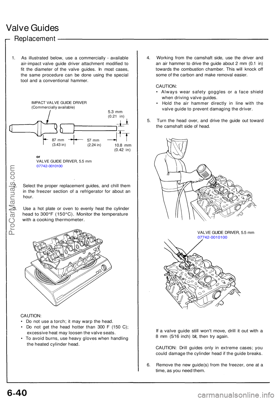
1. A s illustrate d below , us e a commerciall y - availabl e
air-impac t valv e guid e drive r attachmen t modifie d t o
fi t th e diamete r o f th e valv e guides . I n mos t cases ,
th e sam e procedur e ca n b e don e usin g th e specia l
too l an d a conventiona l hammer .
IMPACT VALV E GUID E DRIVE R(Commerciall y available )5.3 m m(0.2 1 in)
87 m m(3.4 3 in)57 m m(2.2 4 in)10. 8 m m(0.4 2 in)
VALV E GUID E DRIVER , 5. 5 m m0774 2-001010 0
2. Selec t th e prope r replacemen t guides , an d chil l the m
i n th e freeze r sectio n o f a refrigerato r fo r abou t a n
hour .
3. Us e a ho t plat e o r ove n t o evenl y hea t th e cylinde r
head t o 300° F ( 150°C) . Monito r th e temperatur e
with a cookin g thermometer .
CAUTION:
• D o no t us e a torch ; i t ma y war p th e head .
• D o no t ge t th e hea d hotte r tha n 30 0 F (15 0 C) ;
excessiv e hea t ma y loose n th e valv e seats .
• T o avoi d burns , us e heav y glove s whe n handlin g
th e heate d cylinde r head . 4
. Workin g fro m th e camshaf t side , us e th e drive r an d
a n ai r hamme r t o driv e th e guid e abou t 2 m m (0. 1 in )
toward s th e combustio n chamber . Thi s wil l knoc k of f
som e o f th e carbo n an d mak e remova l easier .
CAUTION :
• Alway s wea r safet y goggle s o r a fac e shiel d
whe n drivin g valv e guides .
• Hol d th e ai r hamme r directl y i n lin e wit h th e
valv e guid e t o preven t damagin g th e driver .
5 . Tur n th e hea d over , an d driv e th e guid e ou t towar d
th e camshaf t sid e o f head .
VALV E GUID E DRIVER , 5. 5 m m07742-001010 0
If a valv e guid e stil l won' t move , dril l i t ou t wit h a
8 m m (5/1 6 inch ) bit , the n tr y again .
CAUTION : Dril l guide s onl y i n extrem e cases ; yo u
coul d damag e th e cylinde r hea d if th e guid e breaks .
6 . Remov e th e ne w guide(s ) fro m th e freezer , on e a t a
time , a s yo u nee d them .
ProCarManuals.com
Page 117 of 1640
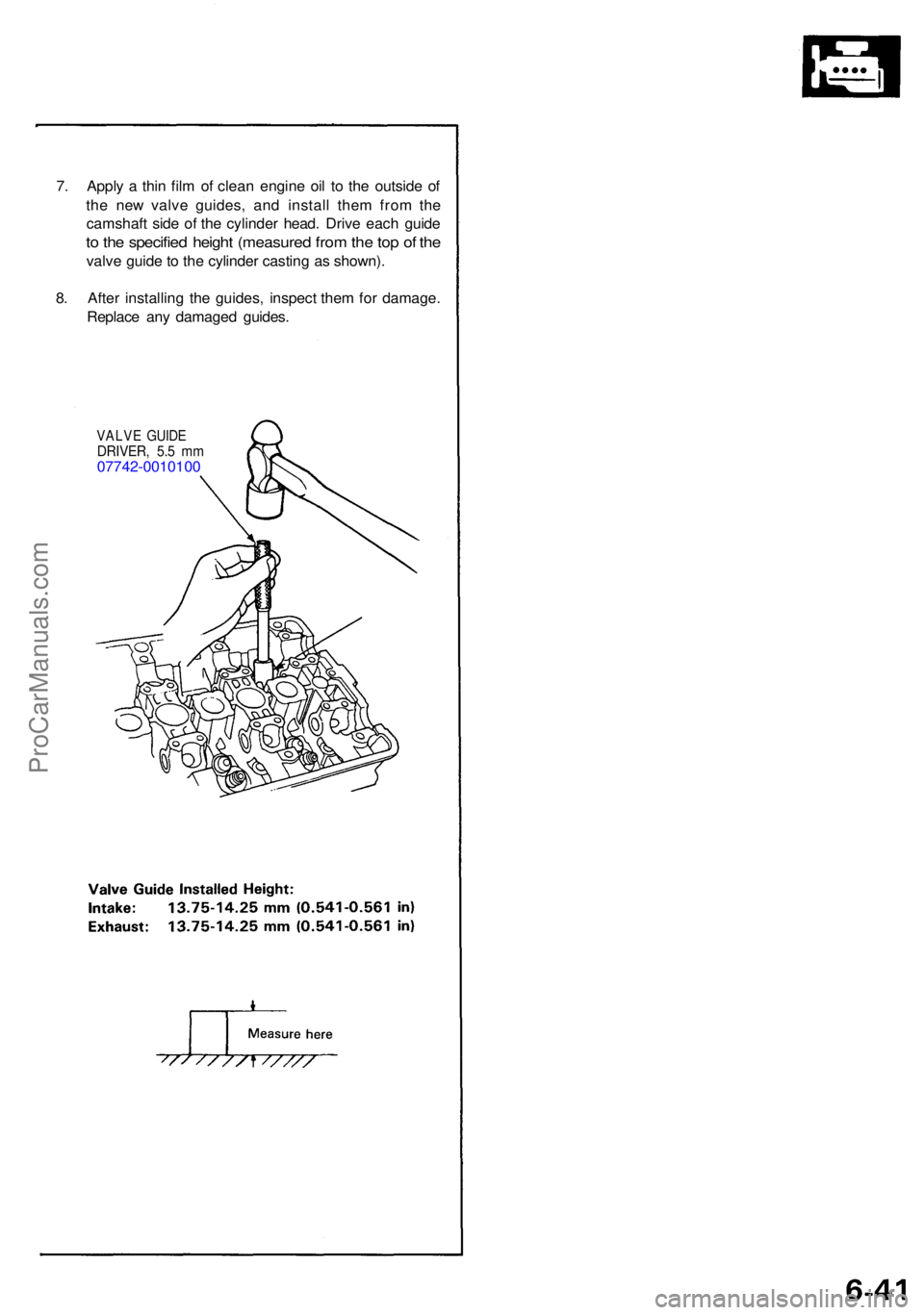
7. Appl y a thi n fil m o f clea n engin e oi l t o th e outsid e o f
th e ne w valv e guides , an d instal l the m fro m th e
camshaf t sid e o f th e cylinde r head . Driv e eac h guid e
to th e specifie d heigh t (measure d fro m th e to p o f th e
valv e guid e to th e cylinde r castin g a s shown) .
8 . Afte r installin g th e guides , inspec t the m fo r damage .
Replac e an y damage d guides .
VALVE GUID EDRIVER , 5. 5 m m07742-001010 0
ProCarManuals.com
Page 118 of 1640
Reaming
NOTE: Fo r ne w valv e guide s only .
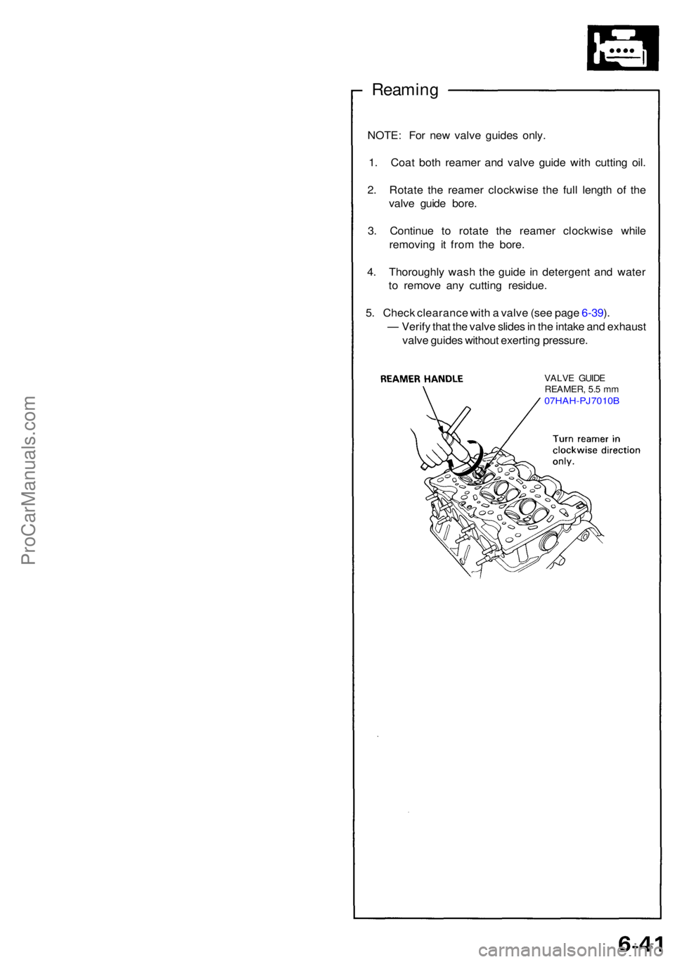
1 . Coa t bot h reame r an d valv e guid e wit h cuttin g oil .
2 . Rotat e th e reame r clockwis e th e ful l lengt h o f th e
valv e guid e bore .
3 . Continu e t o rotat e th e reame r clockwis e whil e
removin g i t fro m th e bore .
4 . Thoroughl y was h th e guid e i n detergen t an d wate r
t o remov e an y cuttin g residue .
5 . Chec k clearanc e wit h a valv e (se e pag e 6-39 ).
— Verif y tha t th e valv e slide s in th e intak e an d exhaus t
valv e guide s withou t exertin g pressure .
VALVE GUID E
REAMER , 5. 5 m m
07HAH-PJ7010 B
ProCarManuals.com
Page 119 of 1640
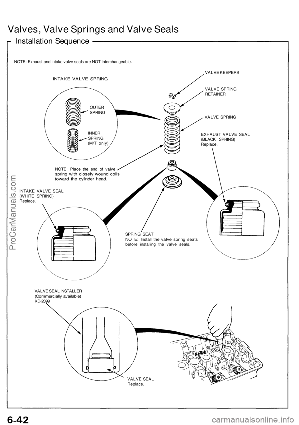
Valves, Valv e Spring s an d Valv e Seal s
Installatio n Sequenc e
NOTE: Exhaust and intake valve seals are NOT interchangeable.
INTAKE VALV E SPRIN G
VALVE KEEPER S
VALV E SPRIN G
RETAINE R
VALVE SPRIN G
EXHAUS T VALV E SEA L
(BLAC K SPRING )
Replace.
NOTE: Plac e th e en d o f valv espring wit h closel y woun d coil stowar d th e cylinde r head .
INTAK E VALV E SEA L
(WHIT E SPRING )
Replace .
SPRING SEA T
NOTE : Instal l th e valv e sprin g seat sbefor e installin g th e valv e seals .
VALV E SEA L INSTALLE R
(Commerciall y available )KD-2899
VALVE SEA L
Replace .
OUTER
SPRIN G
INNE R
SPRIN G
(M/ T only )
ProCarManuals.com
Page 120 of 1640
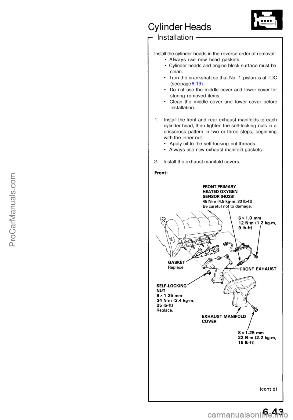
Cylinder Head s
Installatio n
Install th e cylinde r head s in th e revers e orde r o f removal :
• Alway s us e ne w hea d gaskets .
• Cylinde r head s an d engin e bloc k surfac e mus t b e
clean .
• Tur n th e crankshaf t s o tha t No . 1 pisto n i s a t TD C
(se e pag e 6-19 ).
• D o no t us e th e middl e cove r an d lowe r cove r fo r
storin g remove d items .
• Clea n th e middl e cove r an d lowe r cove r befor e
installation .
1 . Instal l th e fron t an d rea r exhaus t manifold s t o eac h
cylinde r head , the n tighte n th e self-lockin g nut s i n a
crisscros s patter n i n tw o o r thre e steps , beginnin g
with th e inne r nut .
• Appl y oi l t o th e self-lockin g nu t threads .
• Alway s us e ne w exhaus t manifol d gaskets .
2 . Instal l th e exhaus t manifol d covers .
ProCarManuals.com