ACURA NSX 1997 Service Repair Manual
Manufacturer: ACURA, Model Year: 1997, Model line: NSX, Model: ACURA NSX 1997Pages: 1503, PDF Size: 57.08 MB
Page 521 of 1503
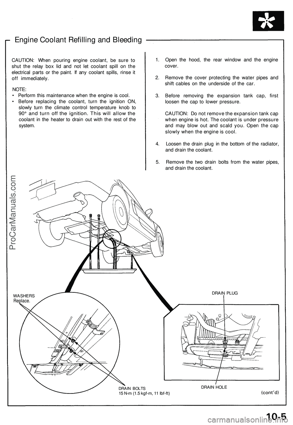
Engine Coolant Refilling and Bleeding
CAUTION: When pouring engine coolant, be sure to
shut the relay box lid and not let coolant spill on the
electrical parts or the paint. If any coolant spills, rinse it
off immediately.
NOTE:
• Perform this maintenance when the engine is cool.
• Before replacing the coolant, turn the ignition ON,
slowly turn the climate control temperature knob to
90° and turn off the ignition. This will allow the
coolant in the heater to drain out with the rest of the
system.
1. Open the hood, the rear window and the engine
cover.
2. Remove the cover protecting the water pipes and
shift cables on the underside of the car.
3. Before removing the expansion tank cap, first
loosen the cap to lower pressure.
CAUTION: Do not remove the expansion tank cap
when engine is hot. The coolant is under pressure
and may blow out and scald you. Open the cap
slowly when the engine is cool.
4. Loosen the drain plug in the bottom of the radiator,
and drain the coolant.
5. Remove the two drain bolts from the water pipes,
and drain the coolant.
WASHERS
Replace.
DRAIN BOLTS
15 N-m (1.5 kgf-m, 11 Ibf-ft)
DRAIN HOLE
DRAIN PLUGProCarManuals.com
Page 522 of 1503
Radiator
Engine Coolan t Refillin g an d Bleedin g (cont'd)
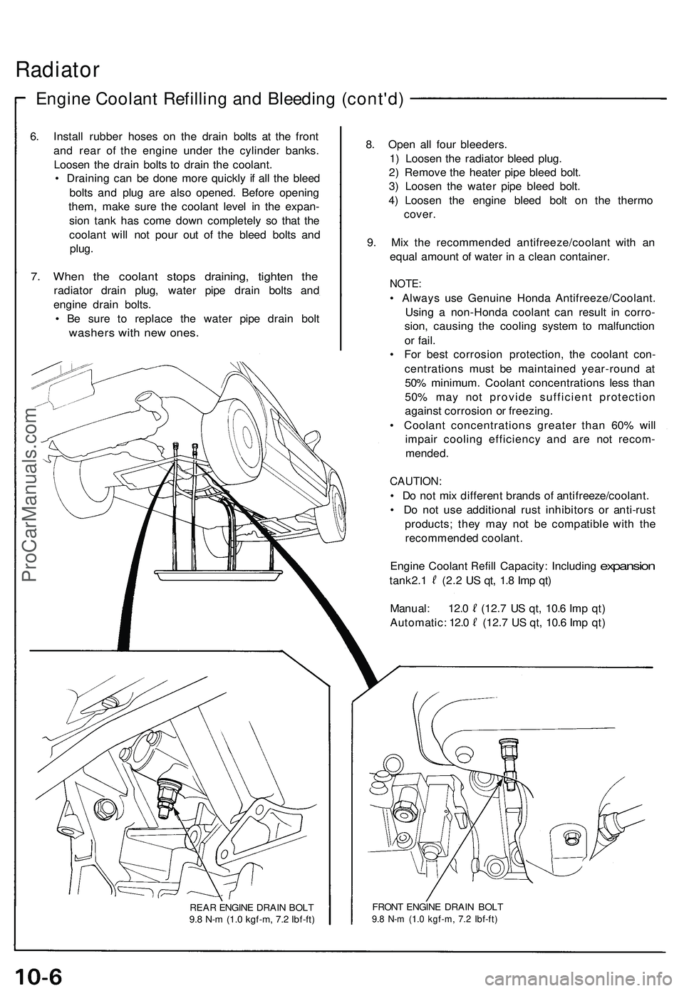
6. Instal l rubbe r hose s o n th e drai n bolt s a t th e fron t
an d rea r o f th e engin e unde r th e cylinde r banks .
Loose n th e drai n bolt s t o drai n th e coolant .
• Drainin g ca n b e don e mor e quickl y i f al l th e blee d
bolt s an d plu g ar e als o opened . Befor e openin g
them , mak e sur e th e coolan t leve l i n th e expan -
sio n tan k ha s com e dow n completel y s o tha t th e
coolan t wil l no t pou r ou t o f th e blee d bolt s an d
plug .
7. Whe n th e coolan t stop s draining , tighte n th e
radiato r drai n plug , wate r pip e drai n bolt s an d
engin e drai n bolts .
• B e sur e t o replac e th e wate r pip e drai n bol t
washer s wit h ne w ones .
REAR ENGIN E DRAI N BOL T
9. 8 N- m (1. 0 kgf-m , 7. 2 Ibf-ft )
8. Ope n al l fou r bleeders .
1 ) Loose n th e radiato r blee d plug .
2 ) Remov e th e heate r pip e blee d bolt .
3 ) Loose n th e wate r pip e blee d bolt .
4 ) Loose n th e engin e blee d bol t o n th e therm o
cover .
9 . Mi x th e recommende d antifreeze/coolan t wit h a n
equa l amoun t o f wate r i n a clea n container .
NOTE:
• Alway s us e Genuin e Hond a Antifreeze/Coolant .
Usin g a non-Hond a coolan t ca n resul t i n corro -
sion , causin g th e coolin g syste m to malfunctio n
o r fail .
• Fo r bes t corrosio n protection , th e coolan t con -
centration s mus t b e maintaine d year-roun d a t
50 % minimum . Coolan t concentration s les s tha n
50 % ma y no t provid e sufficien t protectio n
agains t corrosio n o r freezing .
• Coolan t concentration s greate r tha n 60 % wil l
impai r coolin g efficienc y an d ar e no t recom -
mended .
CAUTION :
• D o no t mi x differen t brand s o f antifreeze/coolant .
• D o no t us e additiona l rus t inhibitor s o r anti-rus t
products ; the y ma y no t b e compatibl e wit h th e
recommende d coolant .
Engin e Coolan t
Refill Capacity : Includin g expansion
tank 2. 1 (2. 2 U S qt , 1. 8 Im p qt )
Manual : 12. 0 (12. 7 U S qt , 10. 6 Im p qt )
Automatic : 12. 0 (12. 7 U S qt , 10. 6 Im p qt )
FRON T ENGIN E DRAI N BOL T9.8 N- m (1. 0 kgf-m , 7. 2 Ibf-ft )
ProCarManuals.com
Page 523 of 1503
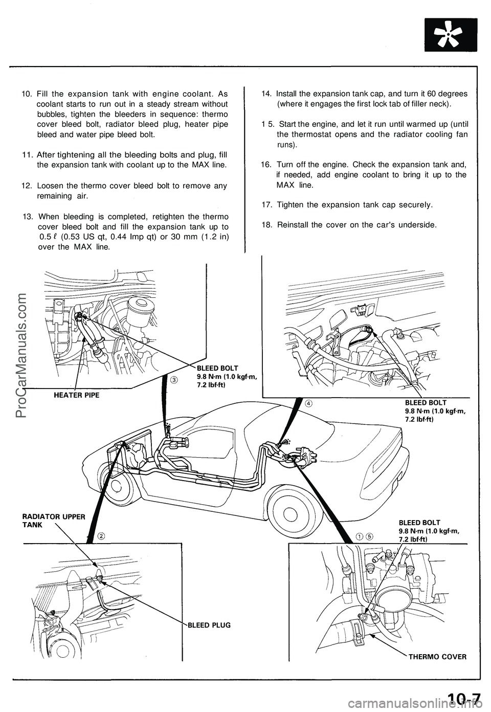
10. Fill the expansion tank with engine coolant. As
coolant starts to run out in a steady stream without
bubbles, tighten the bleeders in sequence: thermo
cover bleed bolt, radiator bleed plug, heater pipe
bleed and water pipe bleed bolt.
11. After tightening all the bleeding bolts and plug, fill
the expansion tank with coolant up to the MAX line.
12. Loosen the thermo cover bleed bolt to remove any
remaining air.
13. When bleeding is completed, retighten the thermo
cover bleed bolt and fill the expansion tank up to
0.5
(0.53
US qt,
0.44
Imp qt) or 30 mm
(1.2
in)
over the MAX line.
14. Install the expansion tank cap, and turn it 60 degrees
(where it engages the first lock tab of filler neck).
1 5. Start the engine, and let it run until warmed up (until
the thermostat opens and the radiator cooling fan
runs).
16. Turn off the engine. Check the expansion tank and,
if needed, add engine coolant to bring it up to the
MAX line.
17. Tighten the expansion tank cap securely.
18. Reinstall the cover on the car's underside.ProCarManuals.com
Page 524 of 1503
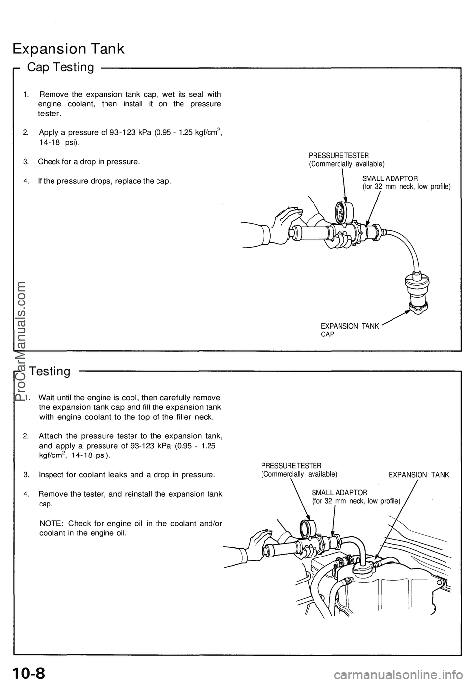
Expansion Tan k
Cap Testin g
1. Remov e th e expansio n tan k cap , we t it s sea l wit h
engin e coolant , the n instal l i t o n th e pressur e
tester.
2. Appl y a pressur e o f 93-12 3 kP a (0.9 5 - 1.2 5 kgf/cm2,
14-1 8 psi) .
3. Chec k fo r a dro p in pressure .
4 . I f th e pressur e drops , replac e th e cap .PRESSUR E TESTE R
(Commerciall y available )
SMAL L ADAPTO R
(fo r 3 2 m m neck , lo w profile )
EXPANSIO N TAN K
CAP
Testin g
1. Wai t unti l th e engin e is cool , the n carefull y remov e
the expansio n tan k ca p an d fil l th e expansio n tan k
with engin e coolan t t o th e to p of the fille r neck .
2. Attac h th e pressur e teste r t o th e expansio n tank ,
an d appl y a pressur e o f 9 3-12 3 kP a (0.9 5 - 1.2 5
kgf/cm
2, 14-1 8 psi) .
3 . Inspec t fo r coolan t leak s an d a dro p i n pressure .
4 . Remov e th e tester , an d reinstal l th e expansio n tan k
cap.
NOTE : Chec k fo r engin e oi l i n th e coolan t and/o r
coolan t i n th e engin e oil .
PRESSUR E TESTE R
(Commerciall y available )
EXPANSION TAN K
SMAL L ADAPTO R
(fo r 3 2 m m neck , lo w profile )
ProCarManuals.com
Page 525 of 1503
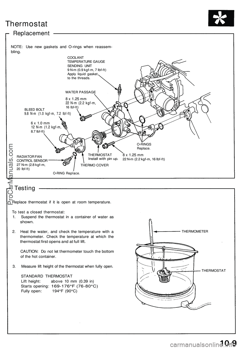
Thermostat
Replacemen t
NOTE: Us e ne w gasket s an d O-ring s whe n reassem -
bling.
COOLAN TTEMPERATUR E GAUG ESENDIN G UNI T
9 N- m (0. 9 kgf-m , 7 Ibf-ft )
Appl y liqui d gaske t
t o th e threads .
WATE R PASSAG E
BLEED BOL T9.8 N- m (1. 0 kgf-m , 7. 2 Ibf-ft )
8 x 1.2 5 mm22 N- m (2. 2 kgf-m ,16 Ibf-ft )
RADIATO R FA N
CONTRO L SENSO R
2 7 N- m (2. 8 kgf-m ,
20 Ibf-ft )
6 x 1. 0 m m12 N- m (1. 2 kgf-m ,8.7 Ibf-ft )
THERMOSTAT
Install wit h pi n up .
THERM O COVE R
8 x 1.2 5 mm22 N- m (2. 2 kgf-m , 1 6 Ibf-ft )
O-RIN G Replace .
Testing
Replac e thermosta t i f i t i s ope n a t roo m temperature .
T o tes t a close d thermostat :
1 . Suspen d th e thermosta t i n a containe r o f wate r a s
shown .
2. Hea t th e water , an d chec k th e temperatur e wit h a
thermometer . Chec k th e temperatur e a t whic h th e
thermosta t firs t open s an d a t ful l lift .
CAUTION : D o no t le t thermomete r touc h th e botto m
o f th e ho t container .
3 . Measur e lif t heigh t o f th e thermosta t whe n full y open .
STANDAR D THERMOSTA T
Lif t height : abov e 1 0 m m (0.3 9 in )
Start s opening :
169-176° F (76-80°C)
Fully open : 194° F (90°C )
THERMOMETE R
THERMOSTA T
O-RINGSReplace .
ProCarManuals.com
Page 526 of 1503
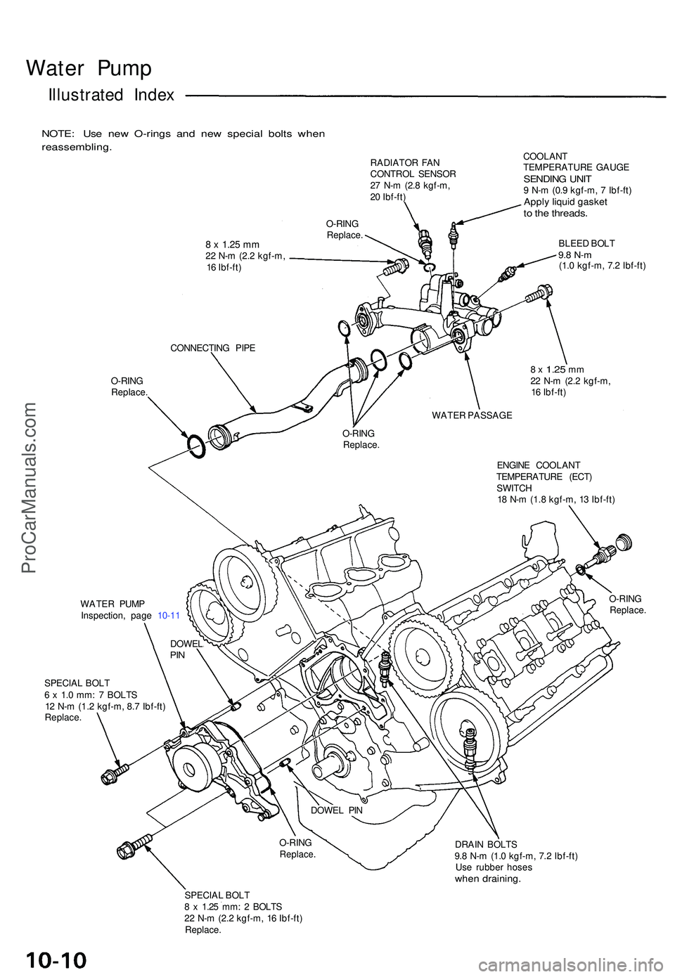
Water Pum p
Illustrate d Inde x
NOTE : Us e ne w O-ring s an d ne w specia l bolt s whe n
reassembling .
RADIATOR FA N
CONTRO L SENSO R
2 7 N- m (2. 8 kgf-m ,
2 0 Ibf-ft )
8 x 1.2 5 mm22 N- m (2. 2 kgf-m ,
1 6 Ibf-ft ) O-RIN
G
Replace .
O-RING
Replace . COOLAN
T
TEMPERATUR E GAUG E
SENDIN G UNI T9 N- m (0. 9 kgf-m , 7 Ibf-ft )Apply liqui d gaske tto th e threads .
BLEED BOL T9.8 N- m(1.0 kgf-m , 7. 2 Ibf-ft )
CONNECTIN G PIP E
8 x 1.2 5 mm22 N- m (2. 2 kgf-m ,
1 6 Ibf-ft )
WATE R PASSAG E
O-RIN G
Replace .
ENGINE COOLAN T
TEMPERATUR E (ECT )
SWITC H
1 8 N- m (1. 8 kgf-m , 1 3 Ibf-ft )
WATE R PUM P
Inspection , pag e 10-1 1 O-RIN
G
Replace .
SPECIAL BOL T
6 x 1. 0 mm : 7 BOLT S
1 2 N- m (1.2 kgf-m , 8. 7 Ibf-ft )
Replace .
DRAIN BOLT S
9. 8 N- m (1. 0 kgf-m , 7. 2 Ibf-ft )
Us e rubbe r hose s
when draining .
SPECIAL BOL T
8 x 1.2 5 mm : 2 BOLT S
2 2 N- m (2. 2 kgf-m , 1 6 Ibf-ft )
Replace .
DOWELPIN
DOWE L PI N
O-RIN G
Replace .
ProCarManuals.com
Page 527 of 1503
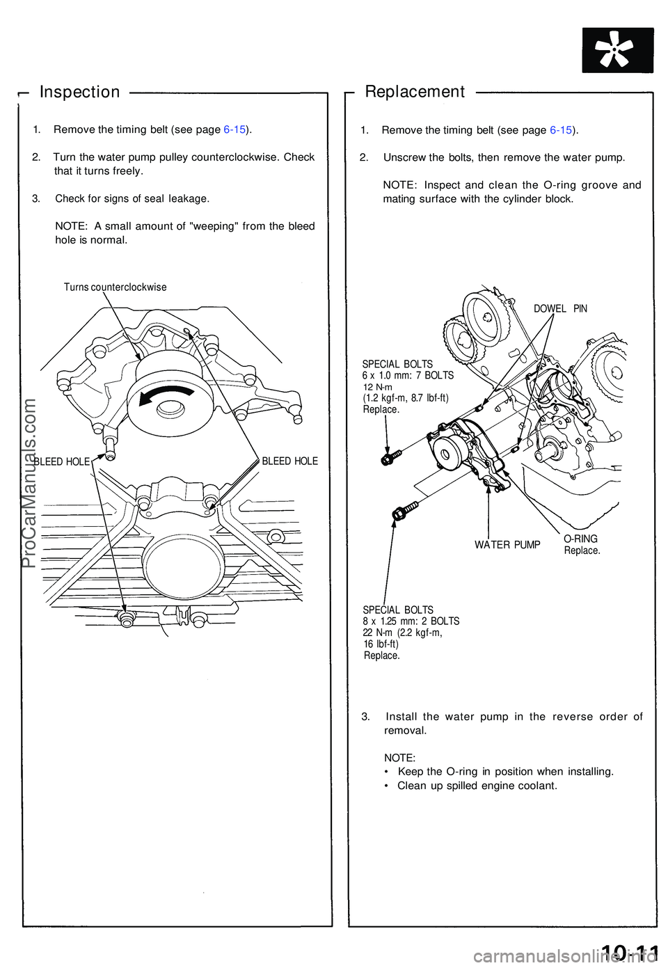
Inspection
1. Remov e th e timin g bel t (se e pag e 6-15 ).
2 . Tur n th e wate r pum p pulle y counterclockwise . Chec k
tha t i t turn s freely .
3. Chec k fo r sign s o f sea l leakage .
NOTE: A smal l amoun t o f "weeping " fro m th e blee d
hol e is normal .
Turns counterclockwis e
BLEED HOL E BLEE
D HOL E
Replacemen t
1. Remov e th e timin g bel t (se e pag e 6-15 ).
2 . Unscre w th e bolts , the n remov e th e wate r pump .
NOTE : Inspec t an d clea n th e O-rin g groov e an d
matin g surfac e wit h th e cylinde r block .
DOWE L PI N
SPECIA L BOLT S
6 x 1. 0 mm : 7 BOLT S
12 N- m(1.2 kgf-m , 8. 7 Ibf-ft )
Replace .
O-RINGReplace .
SPECIA L BOLT S
8 x 1.2 5 mm : 2 BOLT S
2 2 N- m (2. 2 kgf-m ,
1 6 Ibf-ft )
Replace .
3. Instal l th e wate r pum p i n th e revers e orde r o f
removal .
NOTE:
• Kee p th e O-rin g i n positio n whe n installing .
• Clea n u p spille d engin e coolant .
WATER PUM P
ProCarManuals.com
Page 528 of 1503
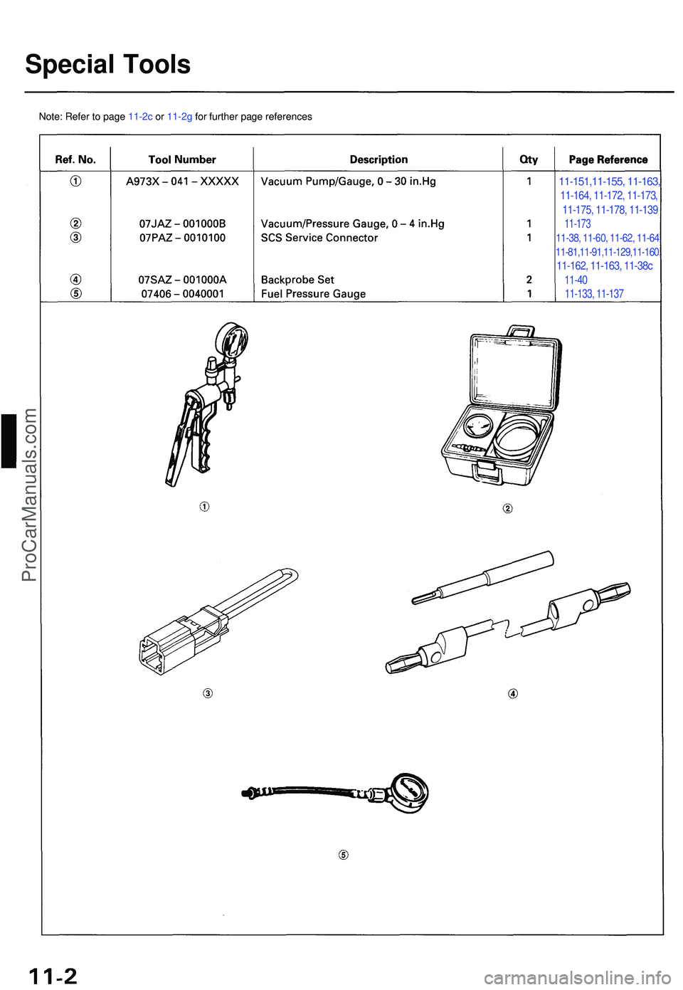
Special Tool s
11-151,11-155, 11-163,
11-164, 11-172, 11-173,
11-175, 11-178, 11-139
11-173
11-38, 11-60, 11-62, 11-64,
11-81,11-91,11-129,11-160,
11-162, 11-163, 11-38c
11-40
11-133, 11-137
Note: Refer to page 11-2c or 11-2g for further page references
ProCarManuals.com
Page 529 of 1503
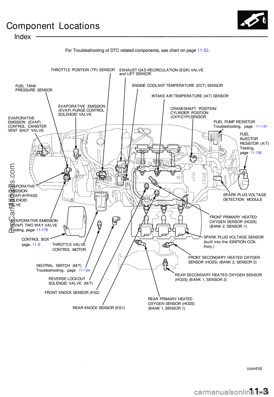
Component Location s
Index
THROTTL E POSITIO N (TP ) SENSO R
FUE L TAN K
PRESSUR E SENSO R
EVAPORATIV E
EMISSIO N (EVAP )
CONTRO L CANISTE R
VEN T SHU T VALV E EXHAUS
T GA S RECIRCULATIO N (EGR ) VALV E
an d LIF T SENSO R
ENGIN E COOLAN T TEMPERATUR E (ECT ) SENSO R
INTAK E AI R TEMPERATUR E (IAT ) SENSO R
CRANKSHAF T POSITION /
CYLINDE R POSITIO N
(CKP/CYP ) SENSO R
FUEL PUM P RESISTO R
Troubleshooting , pag e 11-14 1
FUE L
INJECTO R
RESISTO R (A/T )
Testing ,page 11-13 6
EVAPORATIV
E EMISSIO N
(EVAP ) PURG E CONTRO L
SOLENOI D VALV E
EVAPORATIV E
EMISSION(EVAP) BYPAS S
SOLENOI D
VALV E
EVAPORATIV E EMISSIO N(EVAP) TW O WA Y VALV ETesting , pag e 11-17 8
CONTRO L BO X
page , 1 1 -8 THROTTL E VALV E
CONTRO L MOTO R
NEUTRA L SWITC H (M/T )
Troubleshooting , pag e 11-12 4
REVERS E LOCKOU T
SOLENOI D VALV E (M/T )
FRON T KNOC K SENSO R (KS2 ) SPAR
K PLU G VOLTAG E
DETECTIO N MODUL E
FRON T PRIMAR Y HEATE D
OXYGEN SENSOR (HO2S )
(BAN K 2 , SENSO R 1 )
SPAR K PLU G VOLTAG E SENSO R(built int o th e IGNITIO N COI LAssy. )
FRONT SECONDAR Y HEATE D OXYGE N
SENSO R (HO2S ) (BAN K 2 , SENSO R 2 )
REAR SECONDARY HEATED OXYGEN SENSOR (HO2S) (BANK 1, SENSOR 2)
REA R KNOC K SENSO R (KS1 )
REAR PRIMAR Y HEATE DOXYGEN SENSO R (HO2S )
(BAN K 1 , SENSO R 1 )
(cont'd )
For Troubleshooting of DTC related components, see chart on page 11-52.
ProCarManuals.com
Page 530 of 1503
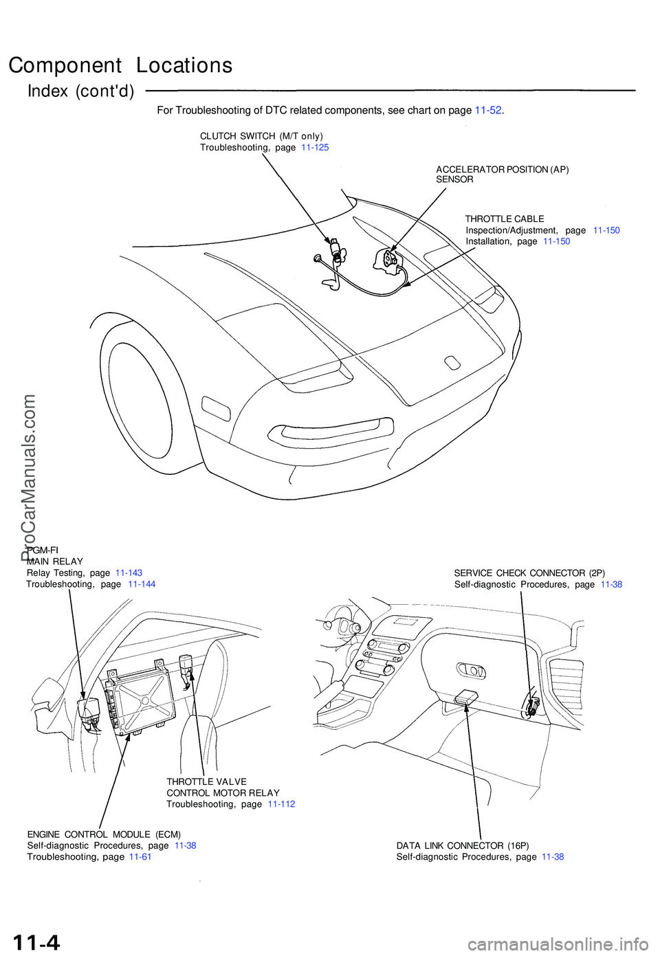
Component Location s
Index (cont'd )
CLUTCH SWITC H (M/ T only )
Troubleshooting , pag e 11-12 5
ACCELERATOR POSITIO N (AP )
SENSO R
THROTTL E CABL E
Inspection/Adjustment , pag e 11-15 0
Installation , pag e 11-15 0
PGM-FIMAIN RELA Y
Rela y Testing , pag e 11-14 3
Troubleshooting , pag e 11-14 4 SERVIC
E CHEC K CONNECTO R (2P )
Self-diagnosti c Procedures , pag e 11-3 8
THROTTL E VALV E
CONTRO L MOTO R RELA Y
Troubleshooting , pag e 11-11 2
ENGIN E CONTRO L MODUL E (ECM )
Self-diagnosti c Procedures , pag e 11-3 8
Troubleshooting , pag e 11-6 1DAT A LIN K CONNECTO R (16P )
Self-diagnosti c Procedures , pag e 11-3 8
For Troubleshooting of DTC related components, see chart on page 11-52.
ProCarManuals.com