ACURA NSX 1997 Service Repair Manual
Manufacturer: ACURA, Model Year: 1997, Model line: NSX, Model: ACURA NSX 1997Pages: 1503, PDF Size: 57.08 MB
Page 491 of 1503
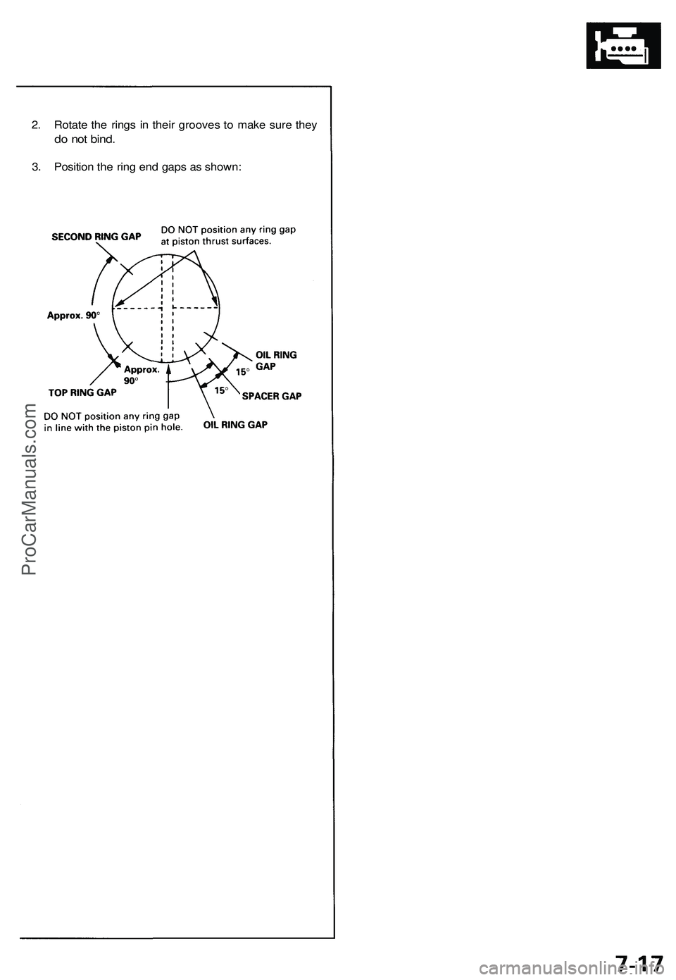
2. Rotate the rings in their grooves to make sure they
do not bind.
3. Position the ring end gaps as shown:ProCarManuals.com
Page 492 of 1503
Piston/Connecting
Rod Assemblie s
Installation
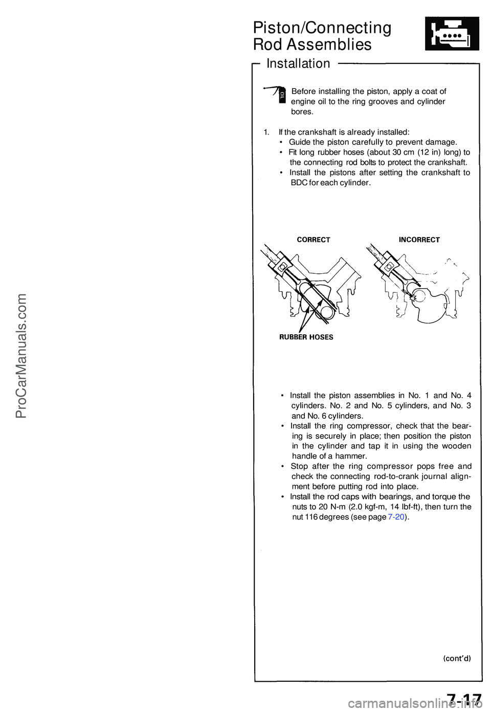
Before installin g th e piston , appl y a coa t o f
engin e oi l t o th e rin g groove s an d cylinde r
bores.
1. I f th e crankshaf t i s alread y installed :
• Guid e th e pisto n carefull y t o preven t damage .
• Fi t lon g rubbe r hose s (abou t 3 0 c m (1 2 in ) long ) t o
th e connectin g ro d bolt s t o protec t th e crankshaft .
• Instal l th e piston s afte r settin g th e crankshaf t t o
BD C fo r eac h cylinder .
• Instal l th e pisto n assemblie s i n No . 1 an d No . 4
cylinders . No . 2 an d No . 5 cylinders , an d No . 3
an d No . 6 cylinders .
• Instal l th e rin g compressor , chec k tha t th e bear -
in g i s securel y i n place ; the n positio n th e pisto n
i n th e cylinde r an d ta p i t i n usin g th e woode n
handl e o f a hammer .
• Sto p afte r th e rin g compresso r pop s fre e an d
chec k th e connectin g rod-to-cran k journa l align -
men t befor e puttin g ro d int o place .
• Instal l th e ro d cap s wit h bearings , an d torqu e th e
nut s t o 2 0 N- m (2. 0 kgf-m , 1 4 Ibf-ft) , the n tur n th e
nu t 11 6 degree s (se e pag e 7-20 ).
ProCarManuals.com
Page 493 of 1503
Piston/Connecting Ro d
Assemblie s
Installation (cont'd )
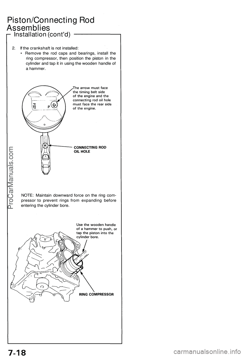
2. I f th e crankshaf t i s no t installed :
• Remov e th e ro d cap s an d bearings , instal l th e
rin g compressor , the n positio n th e pisto n i n th e
cylinde r an d ta p it i n usin g th e woode n handl e o f
a hammer.
NOTE : Maintai n downwar d forc e o n th e rin g com -
presso r t o preven t ring s fro m expandin g befor e
enterin g th e cylinde r bore .
ProCarManuals.com
Page 494 of 1503
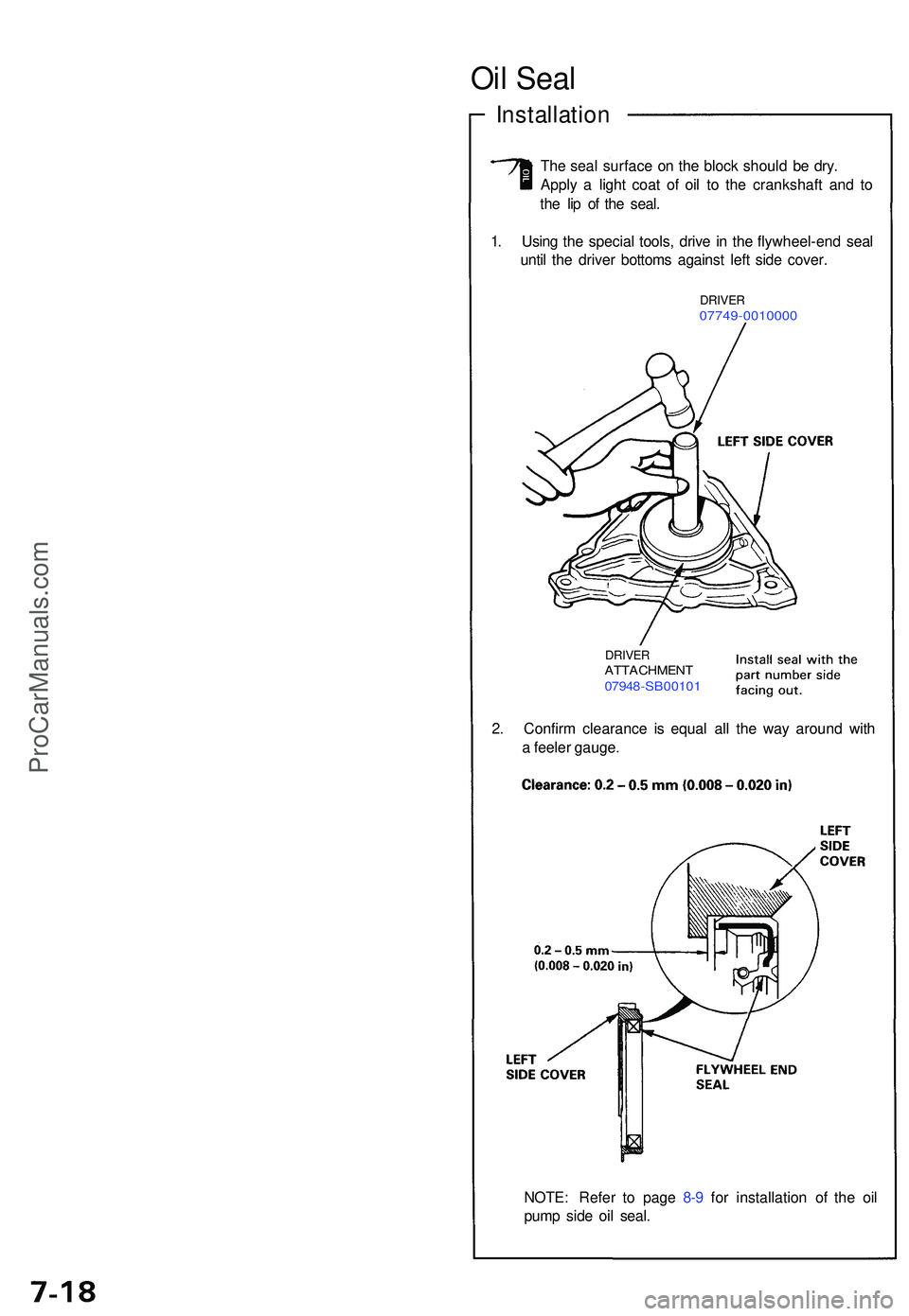
NOTE: Refe r t o pag e 8- 9 fo r installatio n o f th e oi l
pum p sid e oi l seal .
2
. Confir m clearanc e i s equa l al l th e wa y aroun d wit h
a feele r gauge .
DRIVERATTACHMEN T07948-SB0010 1
1. Usin g th e specia l tools , driv e i n th e flywheel-en d sea l
unti l th e drive r bottom s agains t lef t sid e cover .
DRIVE R07749-001000 0
The sea l surfac e o n th e bloc k shoul d b e dry .
Appl y a ligh t coa t o f oi l t o th e crankshaf t an d t o
th e li p o f th e seal .
Oil Sea l
Installatio n
ProCarManuals.com
Page 495 of 1503
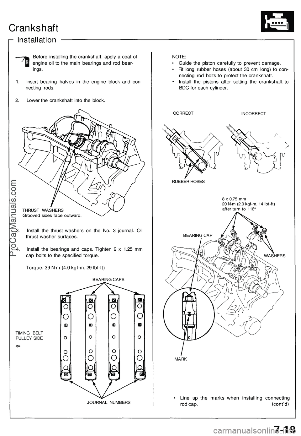
Crankshaft
Installation
Before installing the crankshaft, apply a coat of
engine oil to the main bearings and rod bear-
ings.
1. Insert bearing halves in the engine block and con-
necting rods.
2. Lower the crankshaft into the block.
THRUST WASHERS
Grooved sides face outward.
3. Install the thrust washers on the No. 3 journal. Oil
thrust washer surfaces.
4. Install the bearings and caps. Tighten 9 x 1.25 mm
cap bolts to the specified torque.
Torque: 39 N-m (4.0 kgf-m, 29 Ibf-ft)
TIMING BELT
PULLEY SIDE
JOURNAL NUMBERS
NOTE:
• Guide the piston carefully to prevent damage.
• Fit long rubber hoses (about 30 cm long) to con-
necting rod bolts to protect the crankshaft.
• Install the pistons after setting the crankshaft to
BDC for each cylinder.
CORRECT
INCORRECT
RUBBER HOSES
8 x
0.75
mm
20 N-m (2.0 kgf-m, 14 Ibf-ft)
after turn to 116°
MARK
• Line up the marks when installing connecting
rod
cap.
BEARING CAP
WASHERS
BEARING CAPSProCarManuals.com
Page 496 of 1503
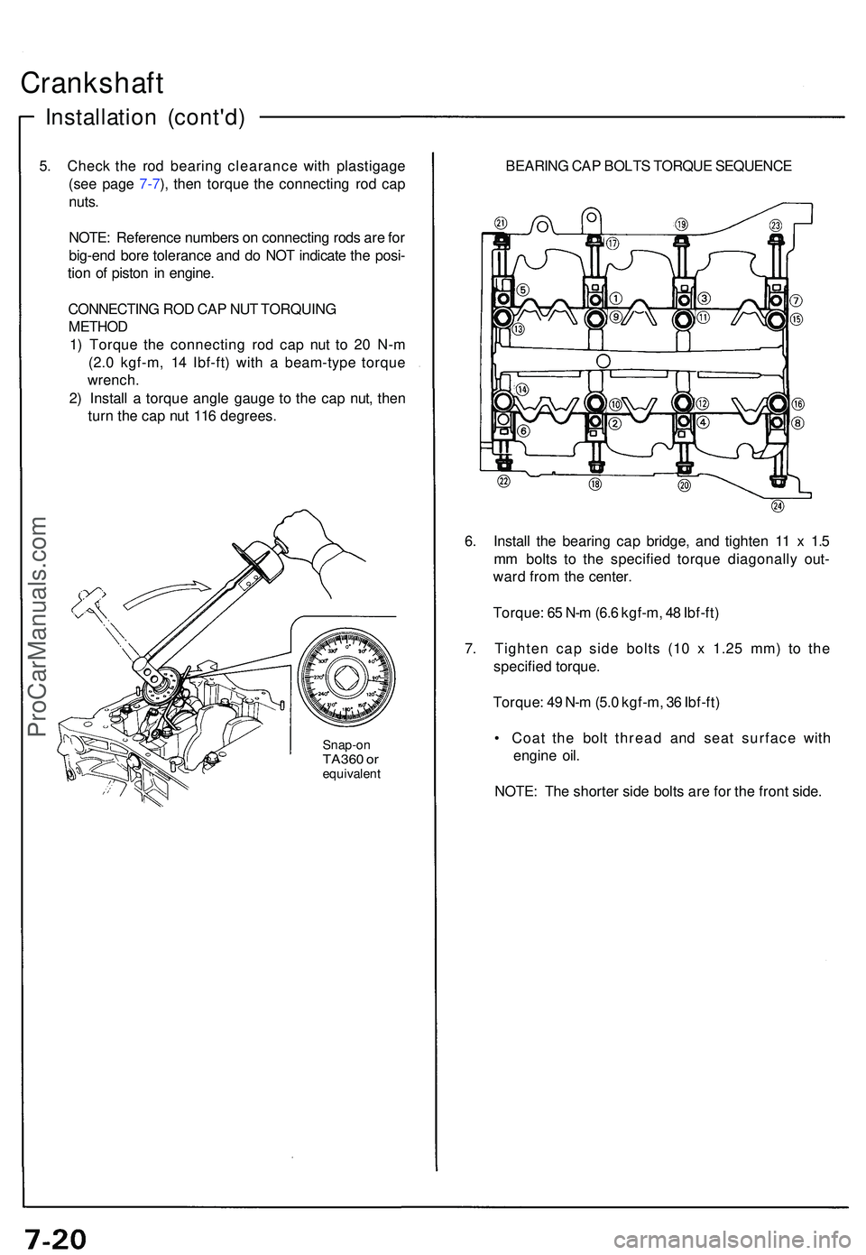
Crankshaft
Installation (cont'd )
5. Chec k th e ro d bearin g clearanc e wit h plastigag e
(se e pag e 7-7 ), the n torqu e th e connectin g ro d ca p
nuts .
NOTE : Referenc e number s o n connectin g rod s ar e fo r
big-en d bor e toleranc e an d d o NO T indicat e th e posi -
tio n o f pisto n i n engine .
CONNECTIN G RO D CA P NU T TORQUIN G
METHO D
1 ) Torqu e th e connectin g ro d ca p nu t t o 2 0 N- m
(2. 0 kgf-m , 1 4 Ibf-ft ) wit h a beam-typ e torqu e
wrench .
2 ) Instal l a torqu e angl e gaug e t o th e ca p nut , the n
tur n th e ca p nu t 11 6 degrees .
Snap-onTA360 o requivalen t
BEARING CAP BOLTS TORQUE SEQUENCE
6 . Instal l th e bearin g ca p bridge , an d tighte n 1 1 x 1. 5
m m bolt s t o th e specifie d torqu e diagonall y out -
war d fro m th e center .
Torque : 6 5 N- m (6. 6 kgf-m , 4 8 Ibf-ft )
7 . Tighte n ca p sid e bolt s (1 0 x 1.2 5 mm ) t o th e
specifie d torque .
Torque : 4 9 N- m (5. 0 kgf-m , 3 6 Ibf-ft )
• Coa t th e bol t threa d an d sea t surfac e wit h
engin e oil .
NOTE : Th e shorte r sid e bolt s ar e fo r th e fron t side .
ProCarManuals.com
Page 497 of 1503
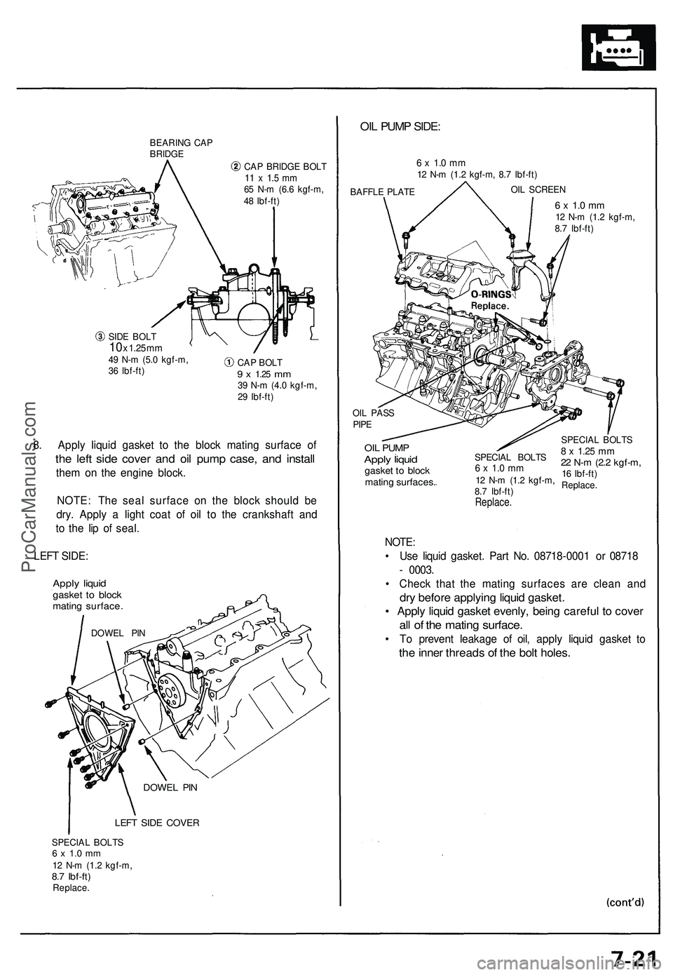
BEARING CA P
BRIDG E
CAP BRIDG E BOL T
11 x 1. 5 m m65 N- m (6. 6 kgf-m ,
4 8 Ibf-ft )
SID E BOL T
10 x 1.2 5 m m49 N- m (5. 0 kgf-m ,
3 6 Ibf-ft ) CA
P BOL T
9 x 1.2 5 mm39 N- m (4. 0 kgf-m ,
2 9 Ibf-ft )
8. Appl y liqui d gaske t t o th e bloc k matin g surfac e o f
the lef t sid e cove r an d oi l pum p case , an d instal l
them o n th e engine block.
NOTE : Th e sea l surfac e o n th e bloc k shoul d b e
dry . Appl y a ligh t coa t o f oi l t o th e crankshaf t an d
t o th e li p o f seal .
LEF T SIDE :
Apply liqui dgaske t t o bloc kmatin g surface .
LEFT SID E COVE R
SPECIA L BOLT S6 x 1. 0 m m12 N- m (1. 2 kgf-m ,8.7 Ibf-ft )Replace .
OIL PUM P SIDE :
6 x 1. 0 m m12 N- m (1. 2 kgf-m , 8. 7 Ibf-ft )
BAFFL E PLAT E OI
L SCREE N
6 x 1. 0 m m12 N- m (1. 2 kgf-m ,
8. 7 Ibf-ft )
OI L PAS S
PIPE
OIL PUM PApply liqui dgaske t t o bloc k
matin g surfaces .
NOTE:
SPECIA L BOLT S6 x 1. 0 m m12 N- m (1. 2 kgf-m ,
8. 7 Ibf-ft )
Replace .
SPECIAL BOLT S8 x 1.2 5 mm22 N- m (2. 2 kgf-m ,16 Ibf-ft )
Replace .
• Us e liqui d gasket . Par t No . 0871 8-000 1 o r 0871 8
- 0003 .
• Chec k tha t th e matin g surface s ar e clea n an d
dry befor e applyin g liqui d gasket .
• Appl y liqui d gaske t evenly , bein g carefu l t o cove r
all o f th e matin g surface .
• T o preven t leakag e o f oil , appl y liqui d gaske t t o
th e inne r thread s o f th e bol t holes .
DOWE L PI N
DOWE L PI N
ProCarManuals.com
Page 498 of 1503
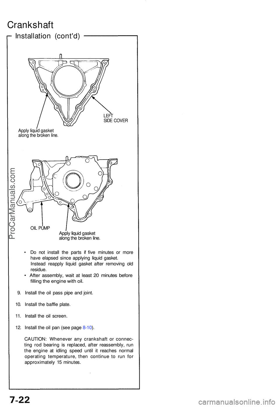
Crankshaft
Installation (cont'd )
LEFTSIDE COVE R
Apply liqui d gaske talong th e broke n line .
OIL PUM PApply liqui d gaske t
alon g th e broke n line .
• D o no t instal l th e part s i f fiv e minute s o r mor e
hav e elapse d sinc e applyin g liqui d gasket .
Instea d reappl y liqui d gaske t afte r removin g ol d
residue .
• Afte r assembly , wai t a t leas t 2 0 minute s befor e
filling th e engin e wit h oil .
9. Instal l th e oi l pas s pip e an d joint .
10 . Instal l th e baffl e plate .
11 . Instal l th e oi l screen .
12 . Instal l th e oi l pa n (se e pag e 8-10 ).
CAUTION : Wheneve r an y crankshaf t o r connec -
tin g ro d bearin g i s replaced , afte r reassembly , ru n
th e engin e a t idlin g spee d unti l i t reache s norma l
operatin g temperature , the n continu e t o ru n fo r
approximatel y 1 5 minutes .
ProCarManuals.com
Page 499 of 1503
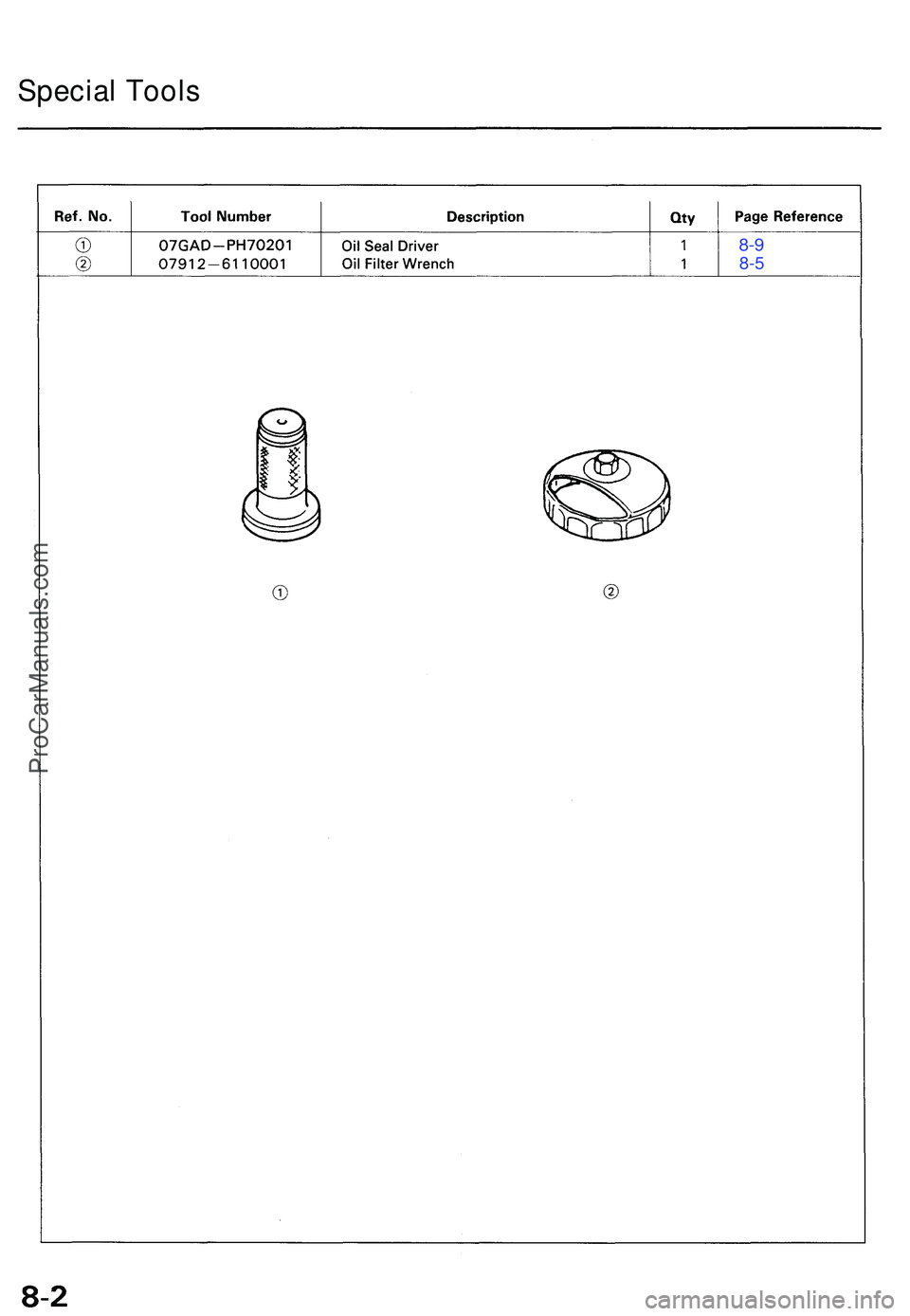
Special Tool s
8-9
8- 5
ProCarManuals.com
Page 500 of 1503
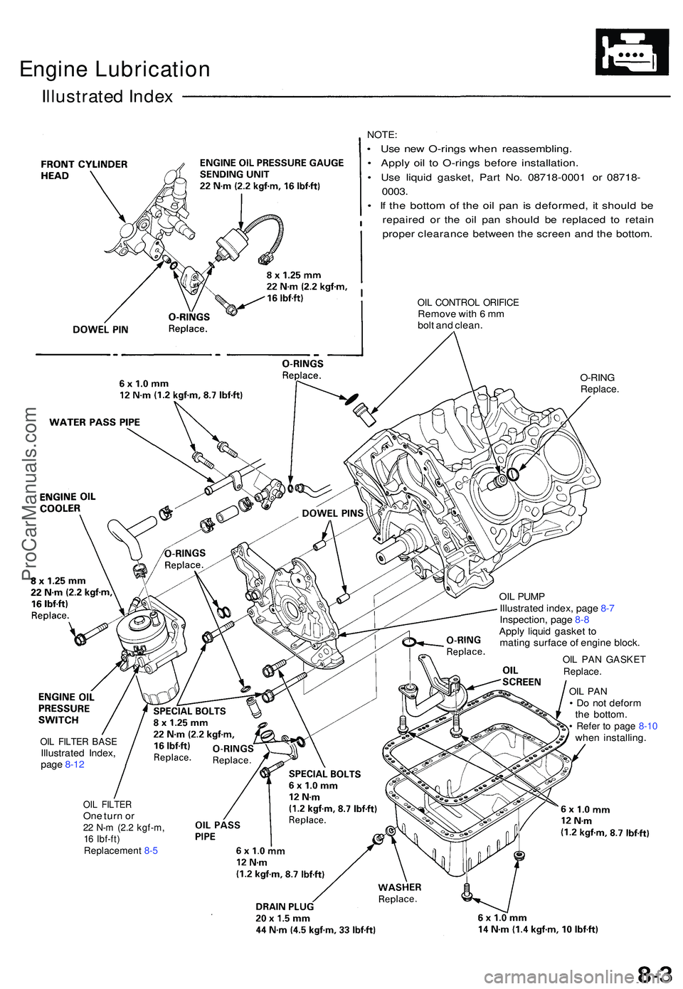
Engine Lubricatio n
Illustrated Index
NOTE:
• Us e ne w O-ring s whe n reassembling .
• Appl y oi l t o O-ring s befor e installation .
• Us e liqui d gasket , Par t No . 0871 8-000 1 o r 0871 8-
0003 .
• I f th e botto m o f th e oi l pa n i s deformed , i t shoul d b e
repaire d o r th e oi l pa n shoul d b e replace d t o retai n
prope r clearanc e betwee n th e scree n an d th e bottom .
OIL CONTRO L ORIFIC ERemove wit h 6 m m
bol t an d clean .
O-RIN GReplace .
OIL FILTE R BAS EIllustrate d Index ,
pag e 8-1 2
OIL FILTE ROne tur n o r22 N- m (2. 2 kgf-m ,16 Ibf-ft )Replacemen t 8- 5
OI L PUM P
Illustrate d index , pag e 8- 7
Inspection , pag e 8 -8
Appl y liqui d gaske t t o
matin g surfac e o f engin e block .
OIL PA N GASKE TReplace.
OIL PA N• D o no t defor m
th e bottom .
• Refe r t o pag e 8-1 0whe n installing .
ProCarManuals.com