sensor ACURA NSX 1997 Service Manual Online
[x] Cancel search | Manufacturer: ACURA, Model Year: 1997, Model line: NSX, Model: ACURA NSX 1997Pages: 1503, PDF Size: 57.08 MB
Page 1054 of 1503
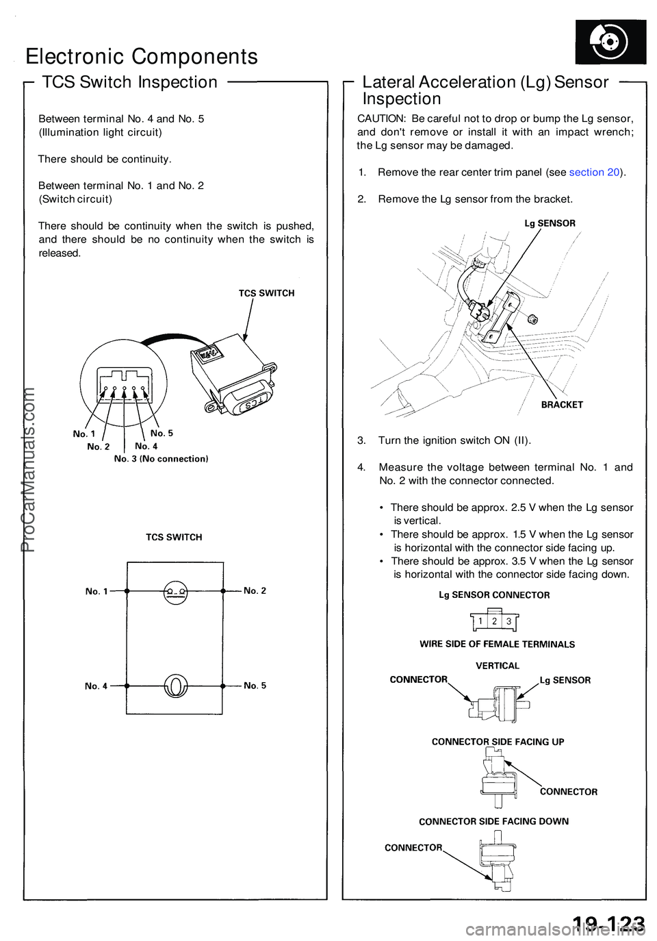
TCS Switc h Inspectio n
Electronic Component s
Between termina l No . 4 an d No . 5
(Illuminatio n ligh t circuit )
Ther e shoul d b e continuity .
Betwee n termina l No . 1 an d No . 2
(Switc h circuit )
Ther e shoul d b e continuit y whe n th e switc h i s pushed ,
an d ther e shoul d b e n o continuit y whe n th e switc h i s
released .
Lateral Acceleratio n (Lg ) Senso r
Inspectio n
CAUTION : B e carefu l no t t o dro p o r bum p th e L g sensor ,
an d don' t remov e o r instal l i t wit h a n impac t wrench ;
th e L g senso r ma y b e damaged .
1 . Remov e th e rea r cente r tri m pane l (se e sectio n 20 ).
2 . Remov e th e L g senso r fro m th e bracket .
3 . Tur n th e ignitio n switc h O N (II) .
4 . Measur e th e voltag e betwee n termina l No . 1 an d
No . 2 wit h th e connecto r connected .
• Ther e shoul d b e approx . 2. 5 V whe n th e L g senso r
i s vertical .
• Ther e shoul d b e approx . 1. 5 V whe n th e L g senso r
i s horizonta l wit h th e connecto r sid e facin g up .
• Ther e shoul d b e approx . 3. 5 V whe n th e L g senso r
i s horizonta l wit h th e connecto r sid e facin g down .
ProCarManuals.com
Page 1055 of 1503
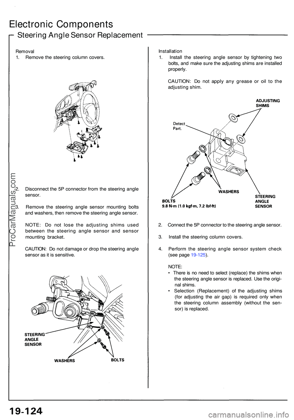
Steering Angl e Senso r Replacemen t
Electronic Component s
Removal
1. Remov e th e steerin g colum n covers . Installatio
n
1 . Instal l th e steerin g angl e senso r b y tightenin g tw o
bolts , an d mak e sur e th e adjustin g shim s ar e installe d
properly .
CAUTION : D o no t appl y an y greas e o r oi l t o th e
adjustin g shim .
2 . Connec t th e 5 P connecto r t o th e steerin g angl e sensor .
3 . Instal l th e steerin g colum n covers .
4 . Perfor m th e steerin g angl e senso r syste m chec k
(se e page 19-125 ).
NOTE :
• Ther e is n o nee d to selec t (replace ) th e shim s whe n
th e steerin g angl e senso r i s replaced . Us e th e origi -
na l shims .
• Selectio n (Replacement ) o f th e adjustin g shim s
(fo r adjustin g th e ai r gap ) i s require d onl y whe n
th e steerin g colum n assembl y (withou t th e sen -
sor ) i s replaced .
2
. Disconnec t th e 5 P connecto r fro m th e steerin g angl e
sensor .
3. Remov e th e steerin g angl e senso r mountin g bolt s
an d washers , the n remov e th e steerin g angl e sensor .
NOTE : D o no t los e th e adjustin g shim s use d
betwee n th e steerin g angl e senso r an d senso r
mountin g bracket .
CAUTION : D o no t damag e o r dro p th e steerin g angl e
senso r a s it i s sensitive .
ProCarManuals.com
Page 1117 of 1503
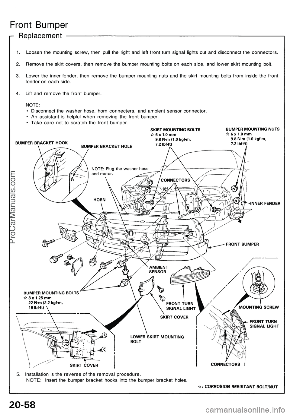
Front Bumper
Replacement
1. Loosen the mounting screw, then pull the right and left front turn signal lights out and disconnect the connectors.
2. Remove the skirt covers, then remove the bumper mounting bolts on each side, and lower skirt mounting bolt.
3. Lower the inner fender, then remove the bumper mounting nuts and the skirt mounting bolts from inside the front
fender on each side.
4. Lift and remove the front bumper.
NOTE:
• Disconnect the washer hose, horn connecters, and ambient sensor connector.
• An assistant is helpful when removing the front bumper.
• Take care not to scratch the front bumper.
5. Installation is the reverse of the removal procedure.
NOTE: Insert the bumper bracket hooks into the bumper bracket holes.ProCarManuals.com
Page 1179 of 1503
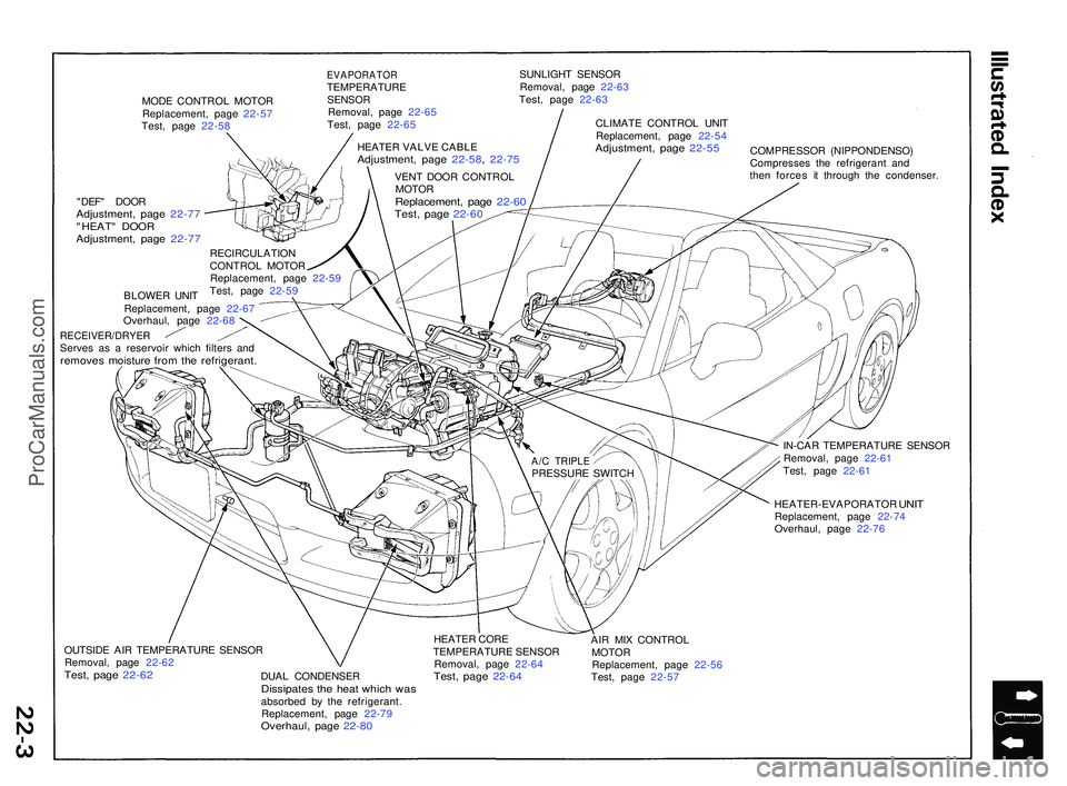
MODE CONTRO L MOTO R
Replacement , pag e 22-5 7
Test , pag e 22-5 8
EVAPORATO RTEMPERATUR ESENSORRemoval , pag e 22-6 5
Test , pag e 22-6 5 SUNLIGH
T SENSO R
Removal , pag e 22-6 3
Test , pag e 22-6 3
CLIMAT E CONTRO L UNI T
Replacement , pag e 22-5 4
Adjustment , pag e 22-5 5COMPRESSO R (NIPPONDENSO )
Compresse s th e refrigeran t an d
the n force s i t throug h th e condenser .
"DEF " DOO R
Adjustment , pag e 22-7 7"HEAT " DOO RAdjustment , pag e 22-7 7
BLOWE R UNI T
Replacement , pag e 22-6 7
Overhaul , pag e 22-6 8
RECEIVER/DRYE RServes a s a reservoi r whic h filter s an dremove s moistur e fro m th e refrigerant .
IN-CAR TEMPERATUR E SENSO R
Removal , pag e 22-6 1
Test , pag e 22-6 1
HEATER-EVAPORATO R
UNITReplacement , pag e 22-7 4
Overhaul , pag e 22-7 6
OUTSID E AI R TEMPERATUR E SENSO R
Removal , pag e 22-6 2
Test, pag e 22-6 2DUAL CONDENSE RDissipates th e hea t whic h wa sabsorbe d b y th e refrigerant .
Replacement , pag e 22-7 9
Overhaul , pag e 22-8 0
HEATE R COR E
TEMPERATUR E SENSO R
Removal , pag e 22-6 4
Test, pag e 22-6 4
AIR MI X CONTRO L
MOTO R
Replacement , pag e 22-5 6
Test , pag e 22-5 7
RECIRCULATIO
N
CONTRO L MOTO R
Replacement , pag e 22-5 9
Test , pag e 22-5 9 HEATE
R VALV E CABL E
Adjustment , pag e 22-58 , 22-7 5
VENT DOO R CONTRO L
MOTO R
Replacement , pag e 22-6 0Test, pag e 22-6 0
A/C TRIPL EPRESSUR E SWITC H
ProCarManuals.com
Page 1184 of 1503
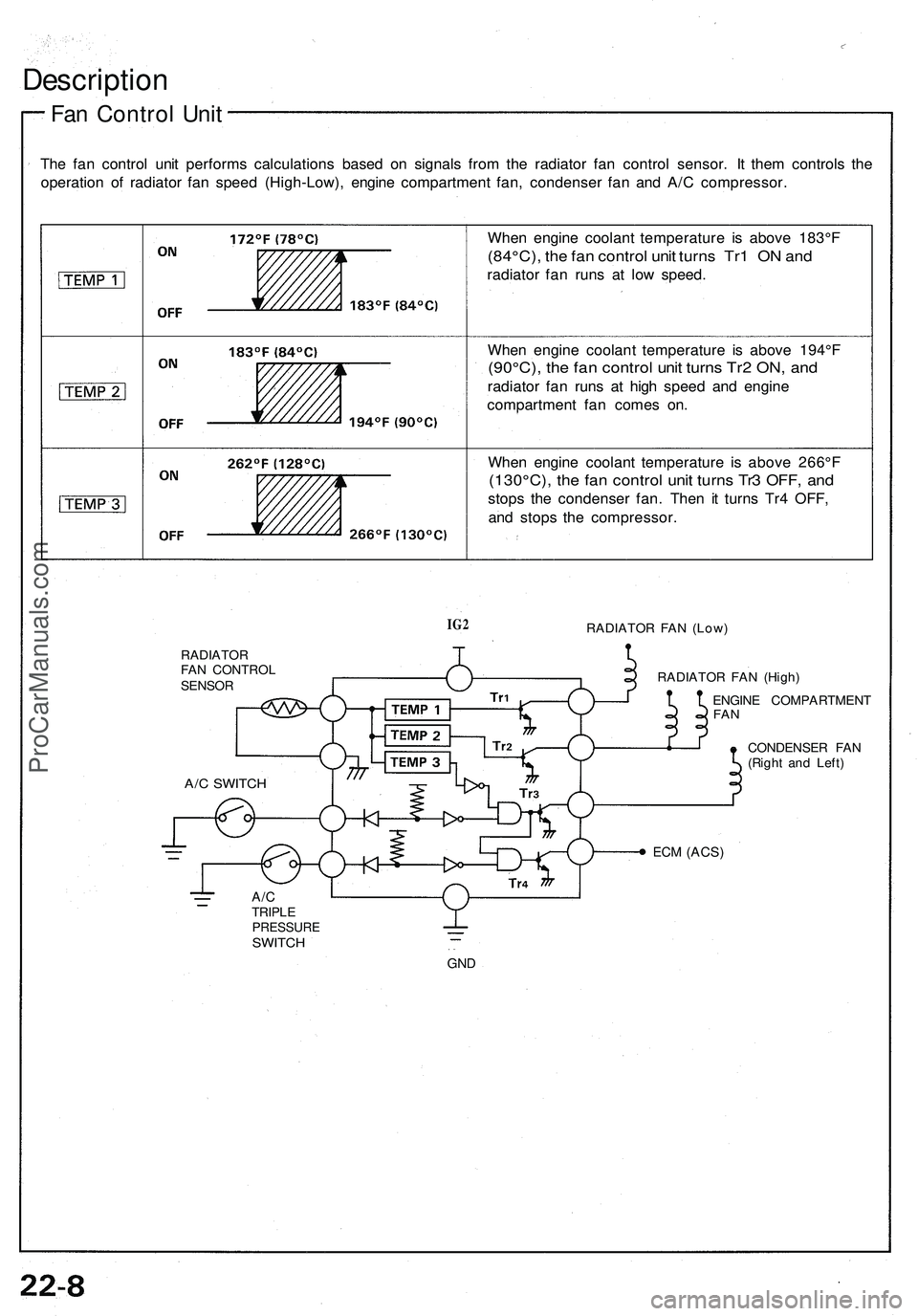
Description
Fan Control Unit
The fan control unit performs calculations based on signals from the radiator fan control sensor. It them controls the
operation of radiator fan speed (High-Low), engine compartment fan, condenser fan and A/C compressor.
When engine coolant temperature is above 183°F
(84°C), the fan control unit turns Tr1 ON and
radiator fan runs at low speed.
When engine coolant temperature is above 194°F
(90°C), the fan control unit turns Tr2 ON, and
radiator fan runs at high speed and engine
compartment fan comes on.
When engine coolant temperature is above 266°F
(130°C), the fan control unit turns Tr3 OFF, and
stops the condenser fan. Then it turns Tr4 OFF,
and stops the compressor.
IG2
RADIATOR FAN (Low)
RADIATOR
FAN CONTROL
SENSOR
RADIATOR FAN (High)
ENGINE COMPARTMENT
FAN
CONDENSER FAN
(Right and Left)
ECM
(ACS)
A/C
TRIPLE
PRESSURE
SWITCH
GND
A/C SWITCHProCarManuals.com
Page 1185 of 1503
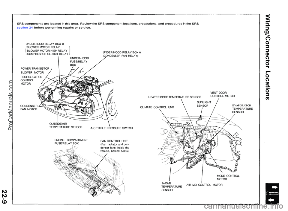
SRS component s ar e locate d in thi s area . Revie w th e SR S componen t locations , precautions , an d procedure s in th e SR S
sectio n 24 befor e performin g repair s o r service .
UNDER-HOO D RELA Y BO X BBLOWE R MOTO R RELA Y
BLOWE R MOTO R HIG H RELA Y
COMPRESSO R CLUTC H RELA Y
POWER TRANSISTO R
BLOWE R MOTO R
RECIRCULATIO N
CONTRO L
MOTO R
CONDENSE R
FA N MOTO R UNDER-HOO
D RELA Y BO X A
(CONDENSE R FA N RELAY )
HEATER COR E TEMPERATUR E SENSO R
CLIMAT E CONTRO L UNI T VEN
T DOO R
CONTRO L MOTO R
OUTSID E AI RTEMPERATUR E SENSO R
A/C TRIPL E PRESSUR E SWITC H
ENGIN E COMPARTMEN T
FUSE/RELA Y BO X
FAN CONTRO L UNI T(Fan radiato r an d con -
dense r fan s insid e th e
vehicle , behin d seats )
EVAPORATO RTEMPERATUR E
SENSO R
MOD E CONTRO L
MOTO R
IN-CA R
TEMPERATUR E
SENSO R AI
R MI X CONTRO L MOTO R
UNDER-HOO
D
FUSE/RELAYBOX
SUNLIGH TSENSOR
ProCarManuals.com
Page 1198 of 1503

In-car Temperatur e Senso r
Remova l
The in-ca r temperatur e senso r assembl y include s a
smal l fa n (aspirato r fan ) t o dra w ai r pas t th e senso r (se e
pag e 22-66 ).
SR S component s ar e locate d in thi s area . Revie w th e SR S
componen t locations , precautions , an d procedure s in th e
SR S sectio n 24 befor e performin g repair s o r service .
1 . Remov e th e cente r consol e pane l (se e pag e 22-54 ).
2 . Remov e th e tw o screw s an d th e in-ca r temperatur e
senso r fro m th e unde r sid e o f th e cente r consol e
panel . B e carefu l no t t o damag e th e cente r consol e
panel.
IN-CA R TEMPERATUR ESENSOR
UNDER SID E O F CENTE R
CONSOL E PANE L
Test
Compar e th e resistanc e readin g betwee n th e No . 1 an d
No. 2 terminal s o f th e in-ca r temperatur e senso r wit h
specification s show n i n th e followin g graph : I t shoul d
be withi n specification .
CAUTION: Th e senso r use s a thermisto r whic h ca n
b e damage d if hig h curren t i s applie d to it durin g test -
ing . Therefore , us e a circui t teste r tha t put s ou t a
measurin g curren t o f 1 m A o r less .
ProCarManuals.com
Page 1199 of 1503
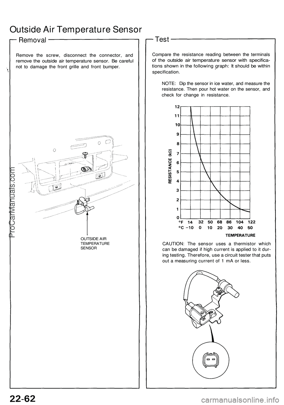
Outside Air Temperature Sensor
Removal
Remove the screw, disconnect the connector, and
remove the outside air temperature sensor. Be careful
not to damage the front grille and front bumper.
OUTSIDE AIR
TEMPERATURE
SENSOR
Test
Compare the resistance reading between the terminals
of the outside air temperature sensor with specifica-
tions shown in the following graph: It should be within
specification.
NOTE: Dip the sensor in ice water, and measure the
resistance. Then pour hot water on the sensor, and
check for change in resistance.
CAUTION: The sensor uses a thermistor which
can be damaged if high current is applied to it dur-
ing testing. Therefore, use a circuit tester that puts
out a measuring current of 1 mA or less.ProCarManuals.com
Page 1200 of 1503
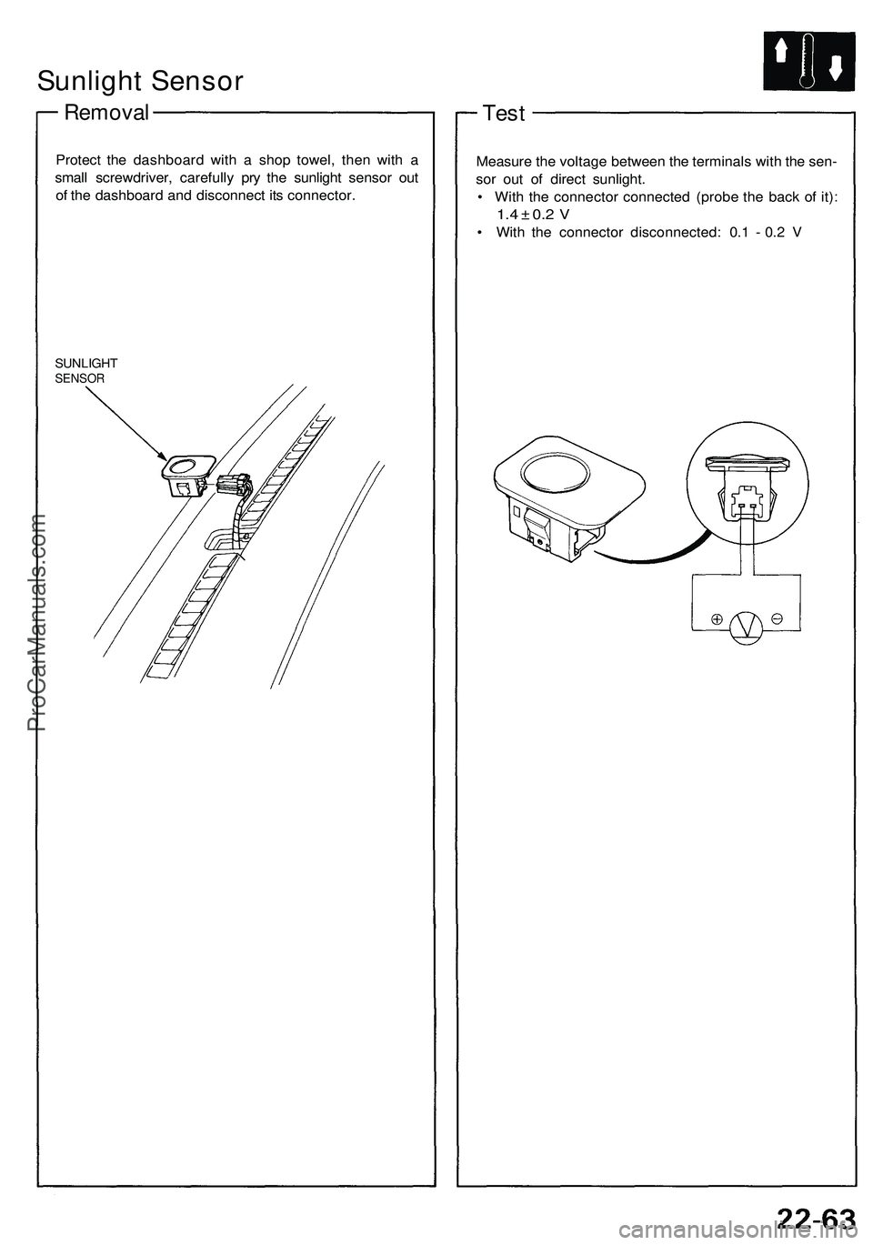
Sunlight Sensor
Removal
Protect the dashboard with a shop towel, then with a
small screwdriver, carefully pry the sunlight sensor out
of the dashboard and disconnect its connector.
SUNLIGHT
SENSOR
Test
Measure the voltage between the terminals with the sen-
sor out of direct sunlight.
• With the connector connected (probe the back of it):
1.4 ± 0.2 V
• With the connector disconnected: 0.1 - 0.2 VProCarManuals.com
Page 1201 of 1503
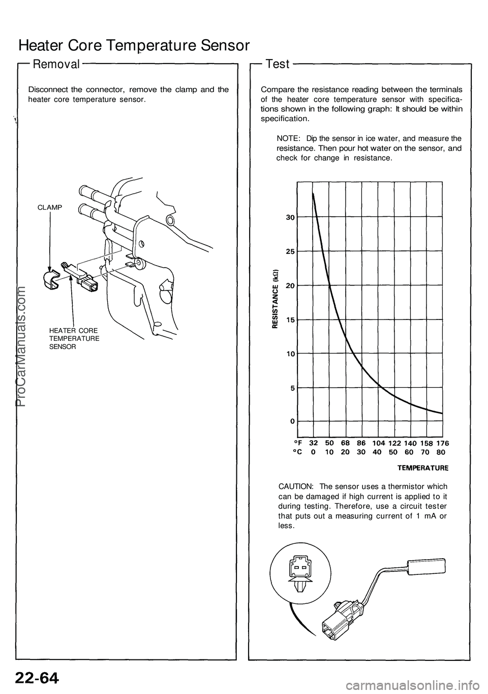
Heater Core Temperature Sensor
Removal
Disconnect the connector, remove the clamp and the
heater core temperature sensor.
CLAMP
HEATER CORE
TEMPERATURE
SENSOR
Compare the resistance reading between the terminals
of the heater core temperature sensor with specifica-
tions shown in the following graph: It should be within
specification.
NOTE: Dip the sensor in ice water, and measure the
resistance. Then pour hot water on the sensor, and
check for change in resistance.
Test
CAUTION: The sensor uses a thermistor which
can be damaged if high current is applied to it
during testing. Therefore, use a circuit tester
that puts out a measuring current of 1 mA or
less.ProCarManuals.com