sensor ACURA NSX 1997 Service Repair Manual
[x] Cancel search | Manufacturer: ACURA, Model Year: 1997, Model line: NSX, Model: ACURA NSX 1997Pages: 1503, PDF Size: 57.08 MB
Page 1363 of 1503
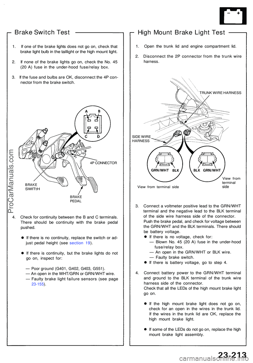
Brake Switc h Tes t
1. I f on e o f th e brak e light s doe s no t g o on , chec k tha t
brak e ligh t bul b in th e tailligh t o r th e hig h moun t light .
2. I f non e o f th e brak e light s g o on , chec k th e No . 4 5
(2 0 A ) fus e i n th e under-hoo d fuse/rela y box .
3 . I f th e fus e an d bulb s ar e OK , disconnec t th e 4 P con -
necto r fro m th e brak e switch .
4P CONNECTO R
BRAKESWITtH
BRAK EPEDAL
4. Chec k fo r continuit y betwee n th e B an d C terminals .
Ther e shoul d b e continuit y wit h th e brak e peda l
pushed .
I f ther e i s n o continuity , replac e th e switc h o r ad -
jus t peda l heigh t (se e sectio n 19 ).
I f ther e i s continuity , bu t th e brak e light s d o no t
g o on , inspec t for :
— Poo r groun d (G401 , G402 , G403 , G551) .
— An ope n in th e WHT/GR N o r GRN/WH T wire .
— Fault y brak e ligh t failur e sensor s (se e pag e
23-155 ).
Hig h Moun t Brak e Ligh t Tes t
1. Ope n th e trun k li d an d engin e compartmen t lid .
2 . Disconnec t th e 2 P connecto r fro m th e trun k wir e
harness .
TRUNK WIR E HARNES S
SID E WIR E
HARNES S
View fro m termina l sid e Vie
w fro m
termina lside
3. Connec t a voltmete r positiv e lea d t o th e GRN/WH T
termina l an d th e negativ e lea d t o th e BL K termina l
o f th e sid e wir e harnes s sid e o f th e connector .
Pus h th e brak e pedal , an d chec k fo r voltag e betwee n
th e GRN/WH T an d th e BL K terminals . Ther e shoul d
b e batter y voltage .
I f ther e i s n o voltage , chec k for :
— Blow n No . 4 5 (2 0 A ) fus e i n th e under-hoo d
fuse/rela y box .
— A n ope n i n th e GRN/WH T o r BL K wire .
— Fault y brak e switch .
I f ther e i s batter y voltage , g o t o ste p 4 .
4 . Connec t batter y powe r t o th e GRN/WH T termina l
an d groun d t o th e BL K termina l o f th e trun k wir e
harnes s sid e o f th e connector .
Chec k tha t al l th e LED s o f th e hig h moun t brak e ligh t
go on .
If th e hig h moun t brak e ligh t doe s no t g o on ,
chec k fo r a n ope n i n th e wire s i n th e trun k lid .
I f th e wire s i n th e trun k li d ar e OK , replac e th e
hig h moun t brak e light .
I f som e o f th e LED s d o no t g o on , replac e th e hig h
moun t brak e ligh t assembly .
ProCarManuals.com
Page 1366 of 1503
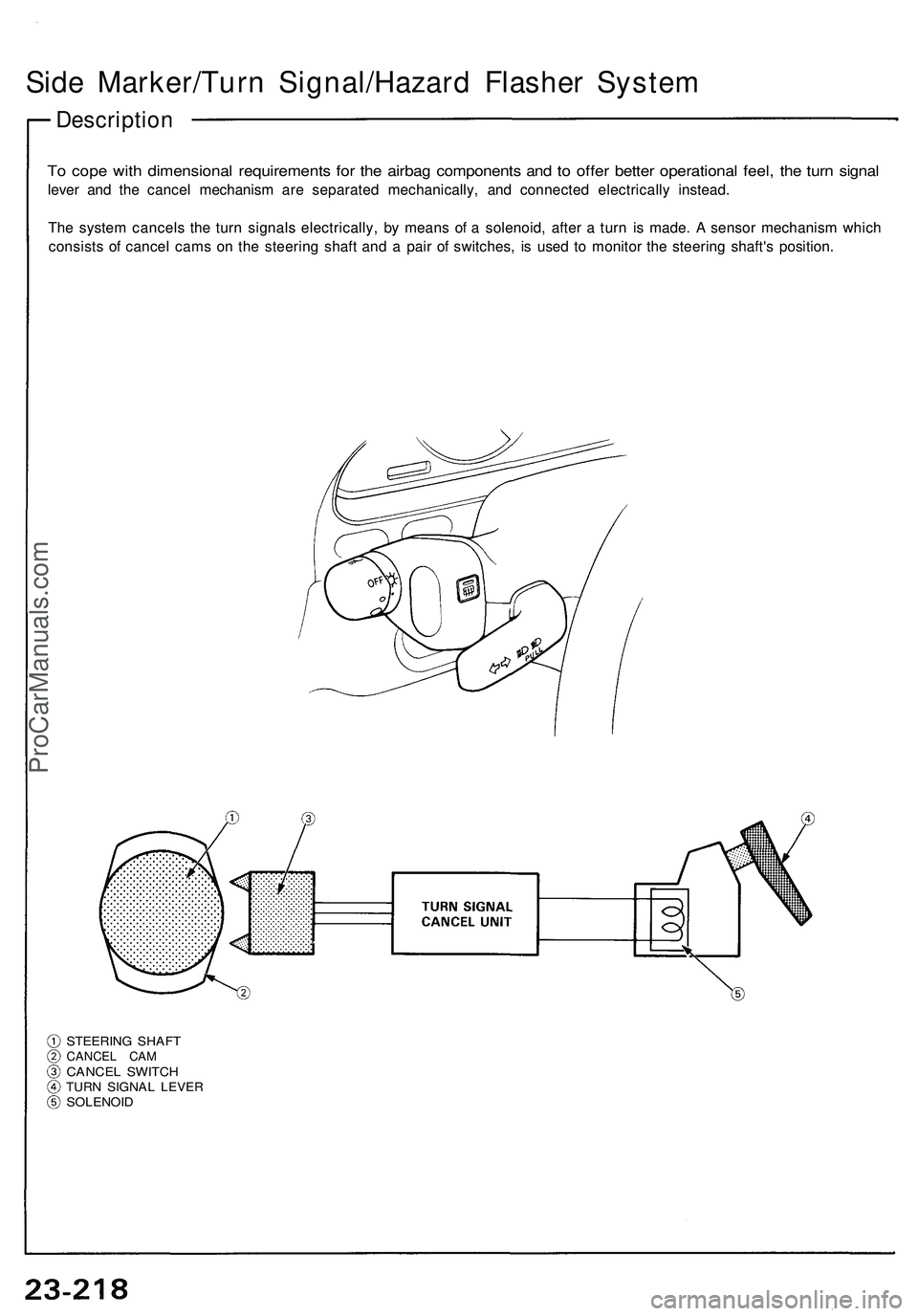
Side Marker/Turn Signal/Hazard Flasher System
Description
To cope with dimensional requirements for the airbag components and to offer better operational feel, the turn signal
lever and the cancel mechanism are separated mechanically, and connected electrically instead.
The system cancels the turn signals electrically, by means of a solenoid, after a turn is made. A sensor mechanism which
consists of cancel cams on the steering shaft and a pair of switches, is used to monitor the steering shaft's position.
STEERING SHAFT
CANCEL CAM
CANCEL SWITCH
TURN SIGNAL LEVER
SOLENOIDProCarManuals.com
Page 1392 of 1503
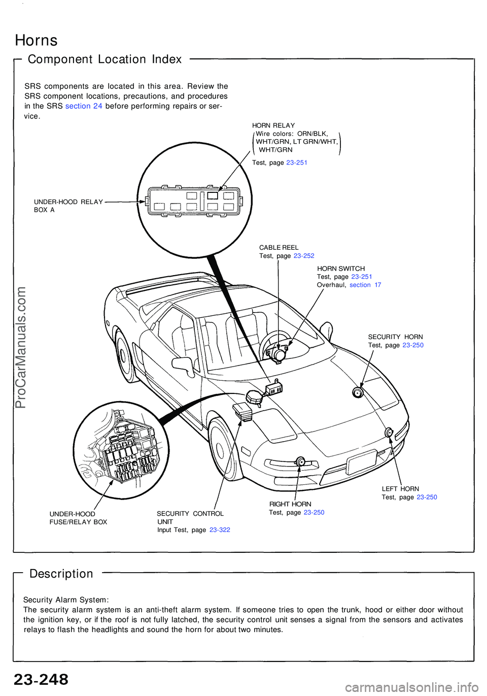
Horns
Componen t Locatio n Inde x
SRS component s ar e locate d i n thi s area . Revie w th e
SR S componen t locations , precautions , an d procedure s
i n th e SR S sectio n 24 befor e performin g repair s o r ser -
vice .
UNDER-HOO D RELA YBOX A
HOR N SWITC HTest, pag e 23-25 1
Overhaul , sectio n 1 7
CABL
E REE L
Test , pag e 23-25 2
SECURITY HOR N
Test , pag e 23-25 0
UNDER-HOO DFUSE/RELAY BO X SECURIT
Y CONTRO LUNITInpu t Test , pag e 23-32 2
RIGHT HOR NTest, pag e 23-25 0 LEF
T HOR N
Test , pag e 23-25 0
Descriptio n
Security Alar m System :
Th e securit y alar m syste m is a n anti-thef t alar m system . I f someon e trie s t o ope n th e trunk , hoo d o r eithe r doo r withou t
th e ignitio n key , o r i f th e roo f i s no t full y latched , th e securit y contro l uni t sense s a signa l fro m th e sensor s an d activate s
relay s t o flas h th e headlight s an d soun d th e hor n fo r abou t tw o minutes .
HORN RELA Y
Wir e colors : ORN/BLK ,
WHT/GRN, L T GRN/WHT ,, WHT/GR N
Test, pag e 23-25 1
ProCarManuals.com
Page 1473 of 1503
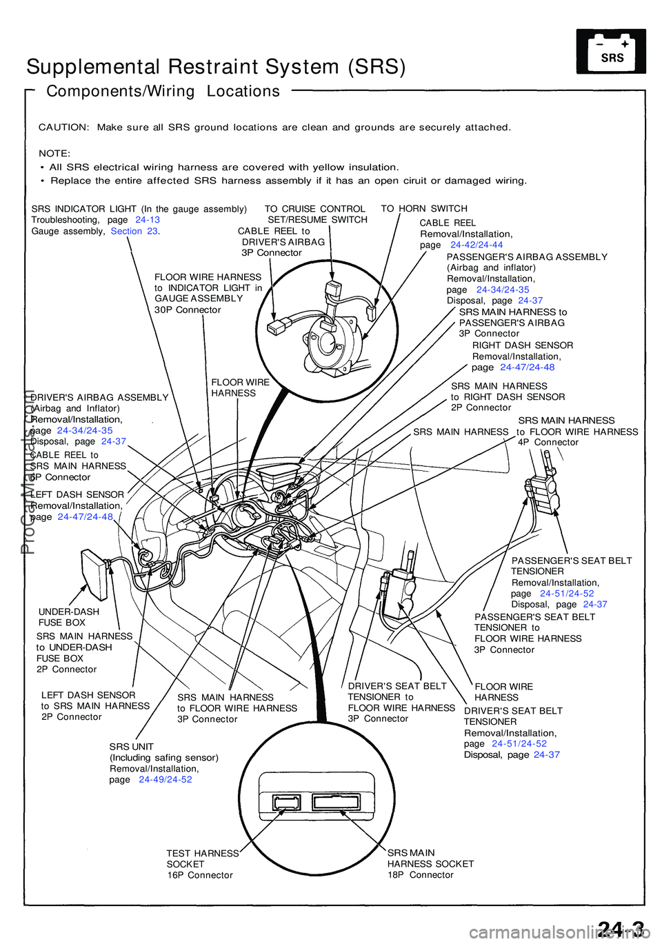
Supplemental Restrain t Syste m (SRS )
Components/Wirin g Location s
CAUTION: Mak e sur e al l SR S groun d location s ar e clea n an d ground s ar e securel y attached .
NOTE:
• Al l SR S electrica l wirin g harnes s ar e covere d wit h yello w insulation .
• Replac e th e entir e affecte d SR S harnes s assembl y i f i t ha s a n ope n cirui t o r damage d wiring .
SRS INDICATO R LIGH T (I n th e gaug e assembly ) T O CRUIS E CONTRO L
Troubleshooting , pag e 24-1 3 SET/RESUME SWITC H
Gaug e assembly , Sectio n 23 . CABL E REE L t o
DRIVER' S AIRBA G
3P Connecto r
TO HOR N SWITC H
DRIVER' S AIRBA G ASSEMBL Y
(Airba g an d Inflator )
Removal/Installation ,page 24-34/24-3 5Disposal, pag e 24-3 7
CABL E REE L t oSR S MAI N HARNES S6P Connecto r
LEFT DAS H SENSO RRemoval/Installation ,page 24-47/24-4 8
CABLE REE LRemoval/Installation ,page 24-42/24-4 4
PASSENGER' S AIRBA G ASSEMBL Y
(Airba g an d inflator )
Removal/Installation ,
pag e 24-34/24-3 5
Disposal , pag e 24-3 7
SRS MAI N HARNES S toPASSENGER' S AIRBA G
3 P Connecto r
RIGH T DAS H SENSO R
Removal/Installation ,
page 24-47/24-4 8
SRS MAI N HARNES S
t o RIGH T DAS H SENSO R
2 P Connecto r
SRS MAI N HARNES SSRS MAI N HARNES S t o FLOO R WIR E HARNES S
4 P Connecto r
UNDER-DAS H
FUS E BO X
SR S MAI N HARNES S
to UNDER-DAS HFUSE BO X
2 P Connecto r
LEF T DAS H SENSO R
t o SR S MAI N HARNES S
2 P Connecto r
SRS UNI T(Includin g safin g sensor )Removal/Installation ,
pag e 24-49/24-5 2 PASSENGER'
S SEA T BEL T
TENSIONE R
Removal/Installation ,
pag e 24-51/24-5 2
Disposal , pag e 24-3 7
PASSENGER' S SEA T BEL T
TENSIONE R t o
FLOO R WIR E HARNES S
3 P Connecto r
FLOO R WIR E
HARNES S
DRIVER' S SEA T BEL T
TENSIONE R
Removal/Installation ,page 24-51/24-5 2Disposal, pag e 24-3 7
TEST HARNES SSOCKET16P Connecto r
SRS MAI NHARNES S SOCKE T
18 P Connecto r
SR
S MAI N HARNES S
t o FLOO R WIR E HARNES S
3 P Connecto r DRIVER'
S SEA T BEL T
TENSIONE R t o
FLOO R WIR E HARNES S
3 P Connecto r
FLOO
R WIR E
HARNES S
FLOOR WIR E HARNES S
t o INDICATO R LIGH T i n
GAUGE ASSEMBL Y
30P Connecto r
ProCarManuals.com
Page 1474 of 1503
Supplemental Restrain t Syste m (SRS )
Descriptio n
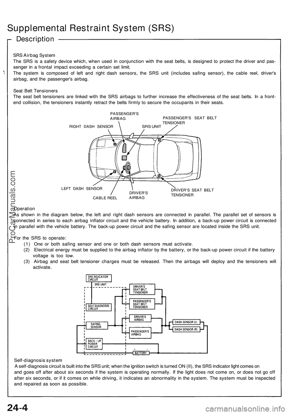
SRS Airba g Syste m
Th e SR S is a safet y devic e which , whe n use d i n conjunctio n wit h th e sea t belts , i s designe d t o protec t th e drive r an d pas -
senge r i n a fronta l impac t exceedin g a certai n se t limit .
Th e syste m is compose d o f lef t an d righ t das h sensors , th e SR S uni t (include s safin g sensor) , th e cabl e reel , driver' s
airbag , an d th e passenger' s airbag .
Sea t Bel t Tensioner s
Th e sea t bel t tensioner s ar e linke d wit h th e SR S airbag s t o furthe r increas e th e effectivenes s o f th e sea t belts . I n a front -
en d collision , th e tensioner s instantl y retrac t th e belt s firml y t o secur e th e occupant s i n thei r seats .
PASSENGER' S
AIRBA G
RIGH T DAS H SENSO R
SRS UNI T
PASSENGER' S SEA T BEL T
TENSIONE R
LEF T DAS H SENSO R
CABL E REE L DRIVER'
S
AIRBA G DRIVER'
S SEA T BEL T
TENSIONE R
Operation
A s show n i n th e diagra m below , th e lef t an d righ t das h sensor s ar e connecte d i n parallel . Th e paralle l se t o f sensor s i s
connecte d i n serie s t o eac h airba g inflato r circui t an d th e vehicl e battery . I n addition , a back-u p powe r circui t i s connecte d
i n paralle l wit h th e vehicl e battery . Th e back-u p powe r circui t an d th e safin g senso r ar e locate d insid e th e SR S unit .
Fo r th e SR S t o operate :
(1 ) On e o r bot h safin g senso r an d on e o r bot h das h sensor s mus t activate .
(2 ) Electrica l energ y mus t b e supplie d t o th e airba g inflato r b y th e battery , o r th e back-u p powe r circui t i f th e batter y
voltag e i s to o low .
(3 ) Airba g an d sea t bel t tensione r charge s mus t b e released . The n th e airbag s wil l deplo y an d th e tensioner s wil l
activate .
Self-diagnosi s syste m
A self-diagnosi s circui t i s buil t int o th e SR S unit ; whe n th e ignitio n switc h is turne d O N (II) , th e SR S indicato r ligh t come s o n
an d goe s of f afte r abou t si x second s i f th e syste m is operatin g normally . I f th e ligh t doe s no t com e on , o r doe s no t g o of f
afte r si x seconds , o r i f i t come s o n whil e driving , i t indicate s a n abnormalit y i n th e system . Th e syste m mus t b e inspecte d
an d repaire d a s soo n a s possible .
ProCarManuals.com
Page 1475 of 1503
Supplemental Restrain t Syste m (SRS )
Genera l Precaution s
Carefully inspec t an y SR S par t befor e yo u instal l it .
D o no t instal l an y par t tha t show s sing s of bein g
droppe d o r improperl y handled , suc h a s dents ,
crack s o r deformation :
— Airba g assembl y (driver' s an d passenger's) .
— Das h sensors .
— Cabl e reel .
— SR S unit .
— Sea t bel t tensione r (driver' s an d passenger's) .
Us e onl y a digita l multimete r t o chec k th e system . I f
it' s no t a Hond a multimeter , mak e sur e it s outpu t i s
1 0 m A (0.0 1 A ) o r les s whe n switche d t o th e smalles t
valu e i n th e ohmmete r range . A teste r wit h a highe r
outpu t coul d damag e th e airba g circui t o r caus e ac -
cidenta l deploymen t an d possibl e injury .
D o no t instal l use d SR S part s fro m anothe r car .
Whe n makin g SR S repairs , us e onl y ne w parts .
Excep t whe n performin g electrica l inspections , alway s
disconnec t bot h th e negativ e cabl e an d positiv e ca -
bl e a t th e batter y befor e beginnin g work .
Replacemen t o f th e combinatio n ligh t an d
wiper/washe r switche s an d cruis e contro l switc h
ca n b e don e withou t removin g th e steerin g wheel :
(se e sectio n 23 ) D
o no t tr y t o disassembl e th e airba g assembly . I f ha s n o
serviceabl e parts . Onc e a n airba g ha s bee n operate d
(deployed) , i t canno t b e repaire d o r reused .
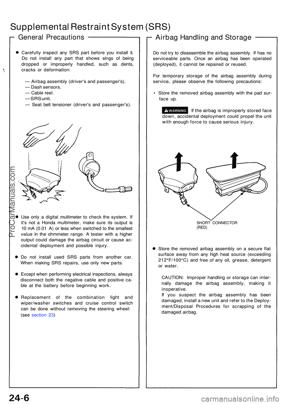
Fo r temporar y storag e of the airba g assembl y durin g
service , pleas e observ e th e followin g precautions :
• Stor e th e remove d airba g assembl y wit h th e pa d sur -
fac e up .
If th e airba g is improperl y store d fac e
down , accidenta l deploymen t coul d prope l th e uni t
wit h enoug h forc e t o caus e seriou s injury .
SHORT CONNECTO R(RED)
Store th e remove d airba g assembl y o n a secur e fla t
surfac e awa y fro m an y hig h hea t sourc e (exceedin g
212°F/100°C ) an d fre e of an y oil , grease , detergen t
o r water .
CAUTION : Imprope r handlin g o r storag e ca n inter -
nall y damag e th e airba g assembly , makin g i t
inoperative .
If yo u suspec t th e airba g assembl y ha s bee n
damaged , instal l a ne w uni t an d refe r t o th e Deploy -
ment/Disposa l Procedure s fo r scrappin g o f th e
damage d airbag .
Airbag Handlin g an d Storag e
ProCarManuals.com
Page 1478 of 1503
Sensor Inspection
CAUTION: Take extra care when painting or doing
body work on any part of the dashboard lower panel.
Avoid direct exposure of the sensors or wiring to heat
guns, welding, or spraying equipment.
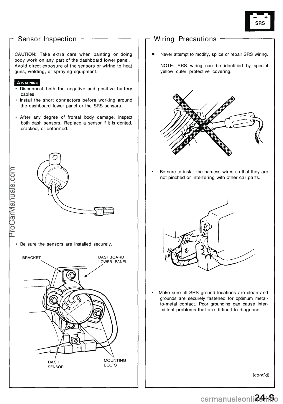
• Disconnect both the negative and positive battery
cables.
• Install the short connectors before working around
the dashboard lower panel or the SRS sensors.
• After any degree of frontal body damage, inspect
both dash sensors. Replace a sensor if it is dented,
cracked, or deformed.
• Be sure the sensors are installed securely.
BRACKET
DASHBOARD
LOWER PANEL
MOUNTING
BOLTS
Wiring Precautions
Never attempt to modify, splice or repair SRS wiring.
NOTE: SRS wiring can be identified by special
yellow outer protective covering.
• Be sure to install the harness wires so that they are
not pinched or interfering with other car parts.
• Make sure all SRS ground locations are clean and
grounds are securely fastened for optimum metal-
to-metal contact. Poor grounding can cause inter-
mittent problems that are difficult to diagnose.
DASH
SENSORProCarManuals.com
Page 1482 of 1503
Supplemental Restrain t Syste m (SRS )
After a collisio n i n whic h th e airbag s wer e deployed , in -
spec t th e following :
1 . Inspec t th e das h sensor s fo r physica l damage . I f
th e sensor s ar e damaged , replac e them .
2 . Inspec t al l th e SR S wir e harnesses . Replace , don' t
repair , an y damage d harnesses .
3 . Inspec t th e cabl e ree l fo r hea t damage . I f ther e i s
an y damage , replac e th e cabl e reel .
4 . Remov e th e passenger' s lowe r dashboar d panel ,
th e glov e bo x lid , an d th e glov e box . Remov e th e
passenger' s airba g assembly , th e mountin g
bracket , an d fram e fro m th e dashboard . Remov e
th e suppor t bracke t fro m th e steerin g colum n
beam .
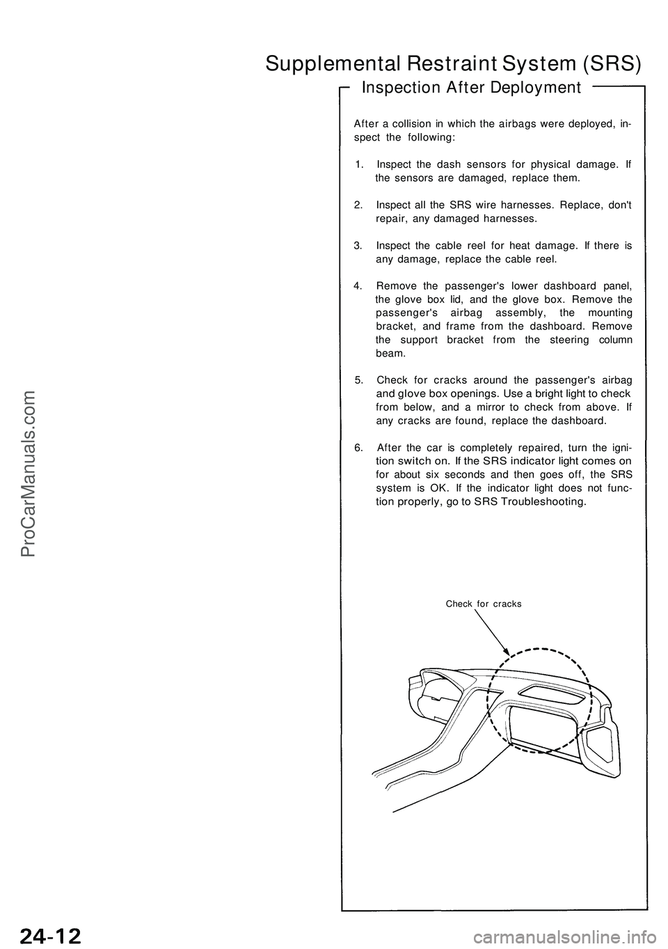
5 . Chec k fo r crack s aroun d th e passenger' s airba g
and glov e bo x openings . Us e a brigh t ligh t t o chec k
from below , an d a mirro r t o chec k fro m above . I f
an y crack s ar e found , replac e th e dashboard .
6 . Afte r th e ca r i s completel y repaired , tur n th e igni -
tion switc h on . I f th e SR S indicato r ligh t come s o n
fo r abou t si x second s an d the n goe s off , th e SR S
syste m is OK . I f th e indicato r ligh t doe s no t func -
tion properly , g o to SR S Troubleshooting .
Check fo r crack s
Inspectio n Afte r Deploymen t
ProCarManuals.com
Page 1483 of 1503
Troubleshooting
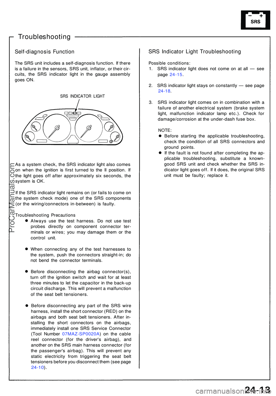
Self-diagnosis Functio n
The SR S uni t include s a self-diagnosi s function . I f ther e
i s a failur e in th e sensors , SR S unit , inflator , o r thei r cir -
cuits , th e SR S indicato r ligh t i n th e gaug e assembl y
goe s ON .
SRS INDICATO R LIGH T
As a syste m check , th e SR S indicato r ligh t als o come s
o n whe n th e ignitio n i s firs t turne d t o th e I I position . I f
th e ligh t goe s of f afte r approximatel y si x seconds , th e
syste m is OK .
I f th e SR S indicato r ligh t remain s o n (o r fail s t o com e o n
th e syste m chec k mode ) on e o f th e SR S component s
(o r th e wiring/connector s in-between ) i s faulty .
Troubleshootin g Precaution s
Always us e th e tes t harness . D o no t us e tes t
probe s directl y o n componen t connecto r ter -
minal s o r wires ; yo u ma y damag e the m o r th e
contro l unit .
Whe n connectin g an y o f th e tes t harnesse s t o
th e system , pus h th e connector s straight-in ; d o
no t ben d th e connecto r terminals .
Befor e disconnectin g th e airba g connector(s) ,
tur n of f th e ignitio n switc h an d wai t fo r a t leas t
thre e minute s t o le t th e capacito r i n th e back-u p
circui t discharge . Thi s wil l preven t a malfunctio n
o f th e sea t bel t tensioners .
Befor e disconnectin g an y par t o f th e SR S wir e
harness , instal l th e shor t connecto r (RED ) o n th e
airbag s an d bot h sea t bel t tensioners . Afte r in -
stallin g th e shor t connector s o n th e airbags ,
immediatel y instal l on e SR S Servic e Connecto r
(Too l Numbe r 07MAZ-SP0020A ) o n th e cabl e
ree l connecto r (fo r th e driver' s airbag) , an d
anothe r o n th e SR S mai n harnes s connecto r (fo r
th e passenger' s airbag) . Thi s wil l preven t an y
stati c electricit y fro m triggerin g th e sea t bel t
tensioner s befor e yo u disconnec t the m (se e pag e
24-10 ).
SR S Indicato r Ligh t Troubleshootin g
Possible conditions :
1. SR S indicato r ligh t doe s no t com e o n a t al l — se e
pag e 24-15 .
2 . SR S indicato r ligh t stay s o n constantl y — se e pag e
24-18 .
3 . SR S indicato r ligh t come s o n in combinatio n wit h a
failur e o f anothe r electrica l syste m (brak e syste m
light , malfunctio n indicato r lam p etc.) . Chec k fo r
damage/corrosio n a t th e under-das h fus e box .
NOTE :
Before startin g th e applicabl e troubleshooting ,
chec k th e conditio n o f al l SR S connector s an d
groun d points .
I f th e faul t i s no t foun d afte r completin g th e ap -
plicabl e troubleshooting , substitut e a known -
goo d SR S uni t an d chec k whethe r th e SR S in -
dicato r ligh t goe s off . I f i t does , th e origina l SR S
uni t mus t b e faulty ; replac e it .
ProCarManuals.com
Page 1498 of 1503
Dash Senso r Remova l
CAUTION :
D o no t damag e th e senso r wiring .
D o no t instal l use d SR S part s fro m anothe r car ,
Whe n repairin g a n SRS , us e onl y ne w parts .
Carefull y inspec t th e das h sensor s fo r sign s o f bein g
droppe d o r improperl y handled , suc h a s dents ,
crack s o r deformation .
1 . Disconnec t th e batter y negativ e cable , the n th e
positiv e cable .
2 . Befor e disconnectin g an y par t o f th e SR S wir e
harness , instal l th e shor t connector s (RED ) (se e pag e
24-10 ).
3 . Remov e th e dashboar d lowe r cover .
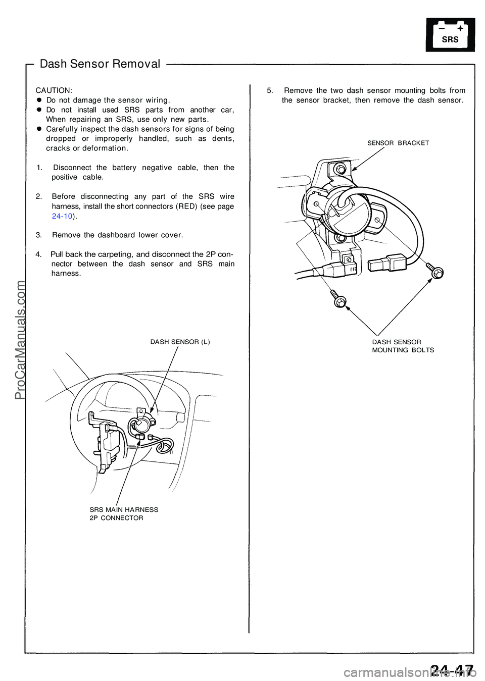
4. Pul l bac k th e carpeting , an d disconnec t th e 2 P con -
necto r betwee n th e das h senso r an d SR S mai n
harness .
DASH SENSO R (L )
SR S MAI N HARNES S2P CONNECTO R
5. Remov e th e tw o das h senso r mountin g bolt s fro m
th e senso r bracket , the n remov e th e das h sensor .
SENSOR BRACKE T
DASH SENSO RMOUNTIN G BOLT S
ProCarManuals.com