sensor ACURA NSX 1997 Service Workshop Manual
[x] Cancel search | Manufacturer: ACURA, Model Year: 1997, Model line: NSX, Model: ACURA NSX 1997Pages: 1503, PDF Size: 57.08 MB
Page 770 of 1503
Road Tes t
positio n
SR S component s ar e locate d in thi s area . Revie w th e SR S componen t locations , precautions , an d procedure s i n th e SR S
( sectio n 24 ) befor e performin g repair s o r service .
1 . Appl y parkin g brak e an d bloc k th e wheels . Star t th e engine , an d war m u p th e engin e t o norma l operatin g temperatur e
(th e coolin g fa n come s on) . (Whe n th e engin e coolan t temperatur e i s belo w norma l operatin g temperature , th e shif t
point i s highe r tha n specifie d vehicl e speed. ) Shif t t o positio n whil e depressin g th e brak e pedal . Depres s th e acceler -
ato r pedal , an d releas e it suddenly . Th e engin e shoul d no t stall .
2 . Chec k tha t th e shif t point s o n a fla t roa d occu r a t th e approximat e speed s show n o n th e nex t page . Als o chec k fo r
abnorma l nois e an d clutc h slippage .
NOTE : Throttl e positio n senso r voltag e represent s th e throttl e opening .
-1 . Remov e th e sea t bac k panel s (se e sectio n 20 ).
-2 . Remov e th e connecto r holde r fro m th e TC S contro l unit , an d disconnec t th e antenn a lead . The n remov e th e TC S
contro l uni t (se e pag e 14-52 ).
NOTE : D o no t disconnec t th e TC S contro l uni t connectors .
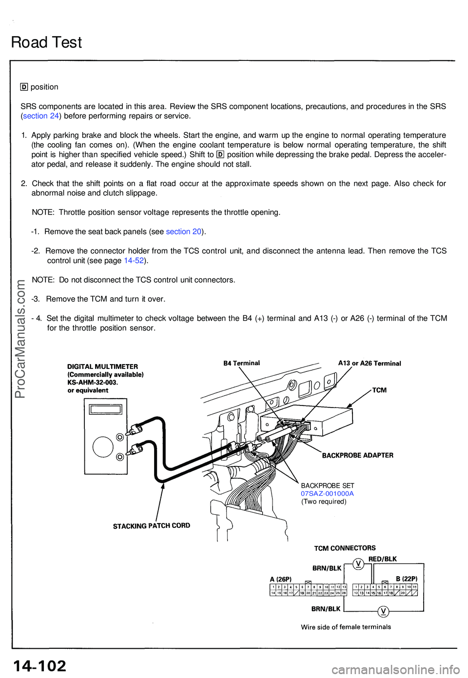
-3 . Remov e th e TC M an d tur n it over .
- 4 . Se t th e digita l multimete r t o chec k voltag e betwee n th e B 4 (+ ) termina l an d A1 3 (- ) o r A2 6 (- ) termina l o f th e TC M
fo r th e throttl e positio n sensor .
BACKPROB E SE T07SAZ-001000 A(Two required )
ProCarManuals.com
Page 779 of 1503
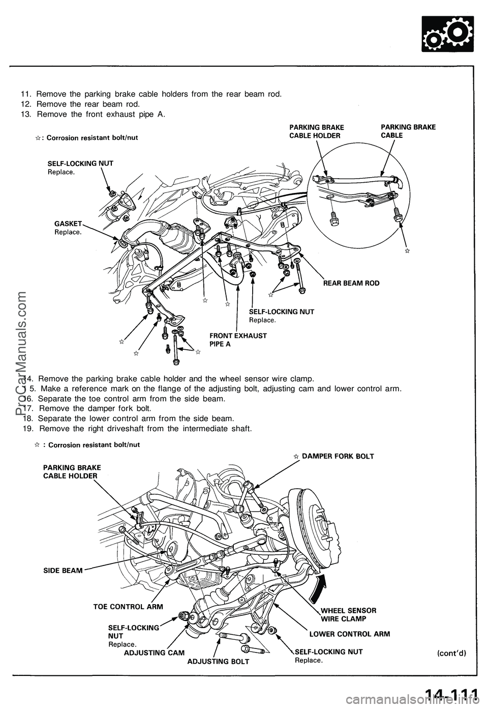
11. Remove the parking brake cable holders from the rear beam rod.
12. Remove the rear beam rod.
13. Remove the front exhaust pipe A.
14. Remove the parking brake cable holder and the wheel sensor wire clamp.
1 5. Make a reference mark on the flange of the adjusting bolt, adjusting cam and lower control arm.
16. Separate the toe control arm from the side beam.
17. Remove the damper fork bolt.
18. Separate the lower control arm from the side beam.
19. Remove the right driveshaft from the intermediate shaft.ProCarManuals.com
Page 780 of 1503
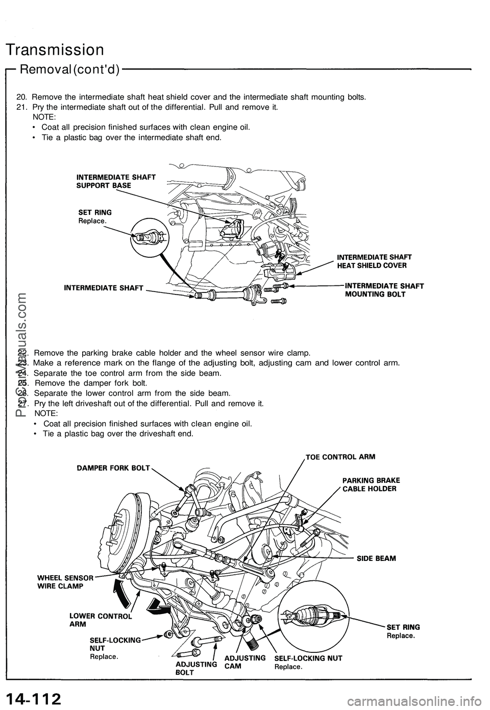
20. Remove the intermediate shaft heat shield cover and the intermediate shaft mounting bolts.
21. Pry the intermediate shaft out of the differential. Pull and remove it.
NOTE:
• Coat all precision finished surfaces with clean engine oil.
• Tie a plastic bag over the intermediate shaft end.
Removal (cont'd)
Transmission
22. Remove the parking brake cable holder and the wheel sensor wire clamp.
23. Make a reference mark on the flange of the adjusting bolt, adjusting cam and lower control arm.
24. Separate the toe control arm from the side beam.
25. Remove the damper fork bolt.
26. Separate the lower control arm from the side beam.
27. Pry the left driveshaft out of the differential. Pull and remove it.
NOTE:
• Coat all precision finished surfaces with clean engine oil.
• Tie a plastic bag over the driveshaft end.ProCarManuals.com
Page 836 of 1503
Installation (cont'd)
Transmission
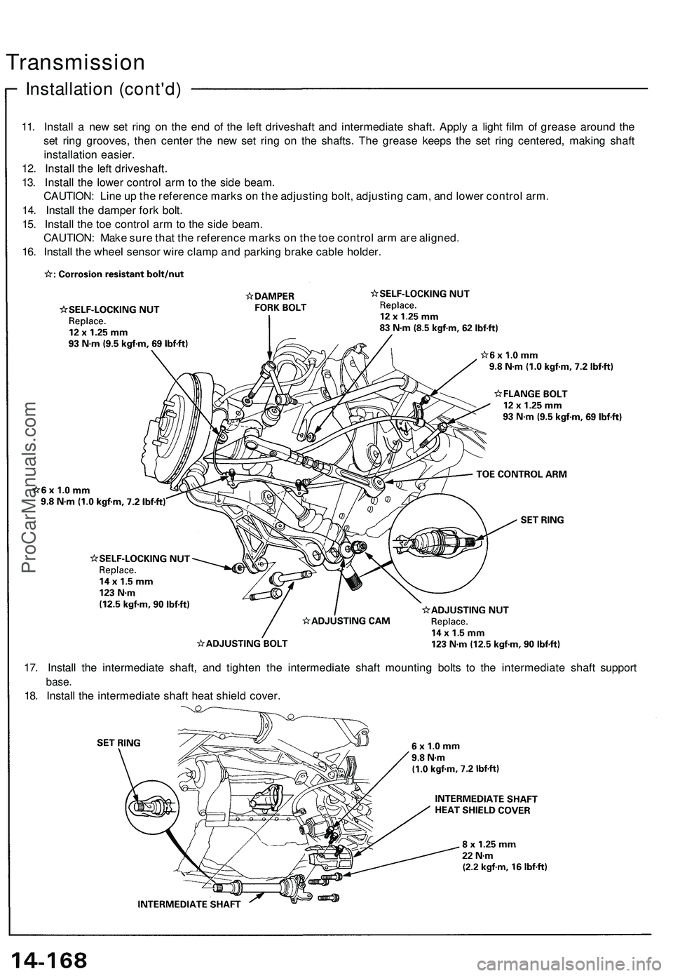
11. Install a new set ring on the end of the left driveshaft and intermediate shaft. Apply a light film of grease around the
set ring grooves, then center the new set ring on the shafts. The grease keeps the set ring centered, making shaft
installation easier.
12. Install the left driveshaft.
13. Install the lower control arm to the side beam.
CAUTION: Line up the reference marks on the adjusting bolt, adjusting cam, and lower control arm.
14. Install the damper fork bolt.
15. Install the toe control arm to the side beam.
CAUTION: Make sure that the reference marks on the toe control arm are aligned.
16. Install the wheel sensor wire clamp and parking brake cable holder.
17. Install the intermediate shaft, and tighten the intermediate shaft mounting bolts to the intermediate shaft support
base.
18. Install the intermediate shaft heat shield cover.ProCarManuals.com
Page 837 of 1503
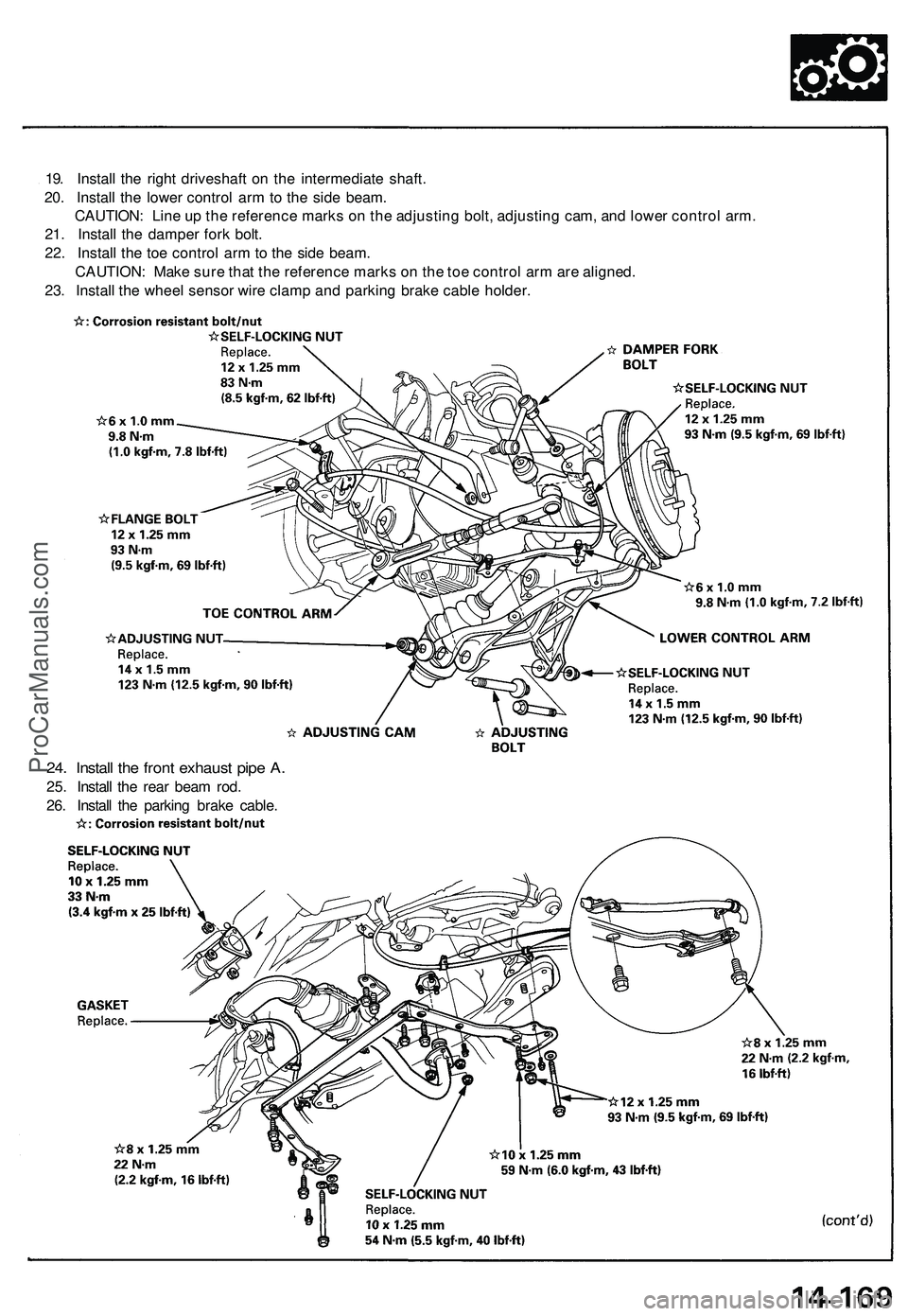
19. Install the right driveshaft on the intermediate shaft.
20. Install the lower control arm to the side beam.
CAUTION: Line up the reference marks on the adjusting bolt, adjusting cam, and lower control arm.
21. Install the damper fork bolt.
22. Install the toe control arm to the side beam.
CAUTION: Make sure that the reference marks on the toe control arm are aligned.
23. Install the wheel sensor wire clamp and parking brake cable holder.
24. Install the front exhaust pipe A.
25. Install the rear beam rod.
26. Install the parking brake cable.ProCarManuals.com
Page 877 of 1503
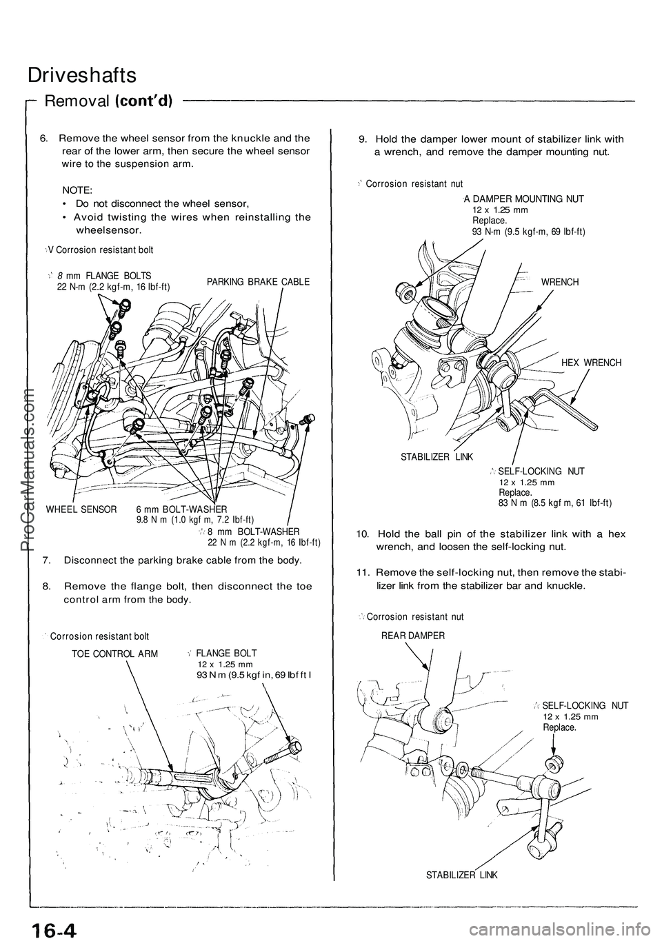
Driveshafts
Removal
6. Remove the wheel sensor from the knuckle and the
rear of the lower arm, then secure the wheel sensor
wire to the suspension arm.
NOTE:
• Do not disconnect the wheel sensor,
• Avoid twisting the wires when reinstalling the
wheel sensor.
V Corrosion resistant bolt
8 mm FLANGE BOLTS
22 N-m (2.2 kgf-m, 16 Ibf-ft)
PARKING BRAKE CABLE
WHEEL SENSOR 6 mm BOLT-WASHER
9.8 N m (1.0 kgf m, 7.2 Ibf-ft)
8 mm BOLT-WASHER
22 N m (2.2 kgf-m, 16 Ibf-ft)
7. Disconnect the parking brake cable from the body.
8. Remove the flange bolt, then disconnect the toe
control arm from the body.
Corrosion resistant bolt
TOE CONTROL ARM
FLANGE BOLT
12 x
1.25
mm
93 N m
(9.5
kgf in, 69 Ibf ft I
9. Hold the damper lower mount of stabilizer link with
a wrench, and remove the damper mounting nut.
Corrosion resistant nut
A DAMPER MOUNTING NUT
12 x
1.25
mm
Replace.
93 N-m (9.5 kgf-m, 69 Ibf-ft)
WRENCH
HEX WRENCH
STABILIZER LINK
SELF-LOCKING NUT
12 x
1.25
mm
Replace.
83 N m (8.5 kgf m, 61 Ibf-ft)
10. Hold the ball pin of the stabilizer link with a hex
wrench, and loosen the self-locking nut.
11. Remove the self-locking nut, then remove the stabi-
lizer link from the stabilizer bar and knuckle.
Corrosion resistant nut
REAR DAMPER
SELF-LOCKING NUT
12 x
1.25
mm
Replace.
STABILIZER LINKProCarManuals.com
Page 897 of 1503
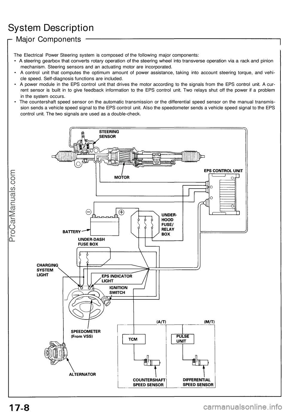
System Descriptio n
Major Component s
The Electrica l Powe r Steerin g syste m is compose d o f th e followin g majo r components :
• A steerin g gearbo x tha t convert s rotar y operatio n o f th e steerin g whee l int o transvers e operatio n vi a a rac k an d pinio n
mechanism . Steerin g sensor s an d a n actuatin g moto r ar e incorporated .
• A contro l uni t tha t compute s th e optimu m amoun t o f powe r assistance , takin g int o accoun t steerin g torque , an d vehi -
cl e speed . Self-diagnosi s function s ar e included .
• A powe r modul e i n th e EP S contro l uni t tha t drive s th e moto r accordin g t o th e signal s fro m th e EP S contro l unit . A cur -
ren t senso r i s buil t i n t o giv e feedbac k informatio n t o th e EP S contro l unit . Tw o relay s shu t of f th e powe r i f a proble m
i n th e syste m occurs .
• Th e countershaf t spee d senso r o n th e automati c transmissio n o r th e differentia l spee d senso r o n th e manua l transmis -
sio n send s a vehicl e spee d signa l t o th e EP S contro l unit . Als o th e speedomete r send s a vehicl e spee d signa l t o th e EP S
contro l unit . Th e tw o signal s ar e use d a s a double-check .
ProCarManuals.com
Page 898 of 1503
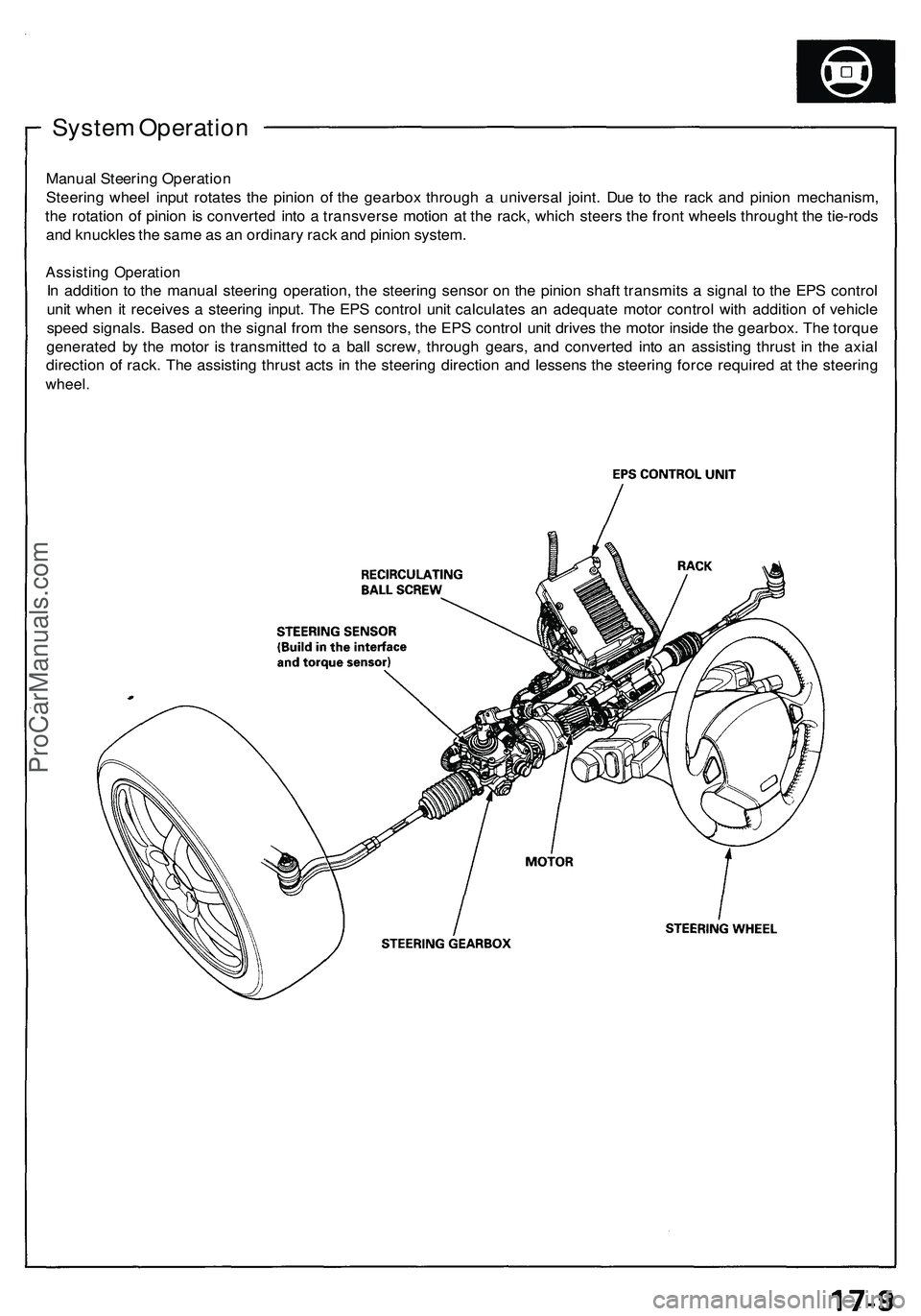
System Operatio n
Manual Steerin g Operatio n
Steerin g whee l inpu t rotate s th e pinio n o f th e gearbo x throug h a universa l joint . Du e t o th e rac k an d pinio n mechanism ,
th e rotatio n o f pinio n is converte d int o a transvers e motio n a t th e rack , whic h steer s th e fron t wheel s through t th e tie-rod s
an d knuckle s th e sam e a s a n ordinar y rac k an d pinio n system .
Assistin g Operatio n
In additio n t o th e manual steering operation , th e steerin g senso r o n th e pinio n shaf t transmit s a signa l t o th e EP S contro l
uni t whe n i t receive s a steerin g input . Th e EP S contro l uni t calculate s a n adequat e moto r contro l wit h additio n o f vehicl e
spee d signals . Base d o n th e signa l fro m th e sensors , th e EP S contro l uni t drive s th e moto r insid e th e gearbox . Th e torqu e
generate d b y th e moto r i s transmitte d t o a bal l screw , throug h gears , an d converte d int o a n assistin g thrus t i n th e axia l
directio n o f rack . Th e assistin g thrus t act s i n th e steerin g directio n an d lessen s th e steerin g forc e require d a t th e steerin g
wheel.
ProCarManuals.com
Page 899 of 1503
System Description
Function and Operation
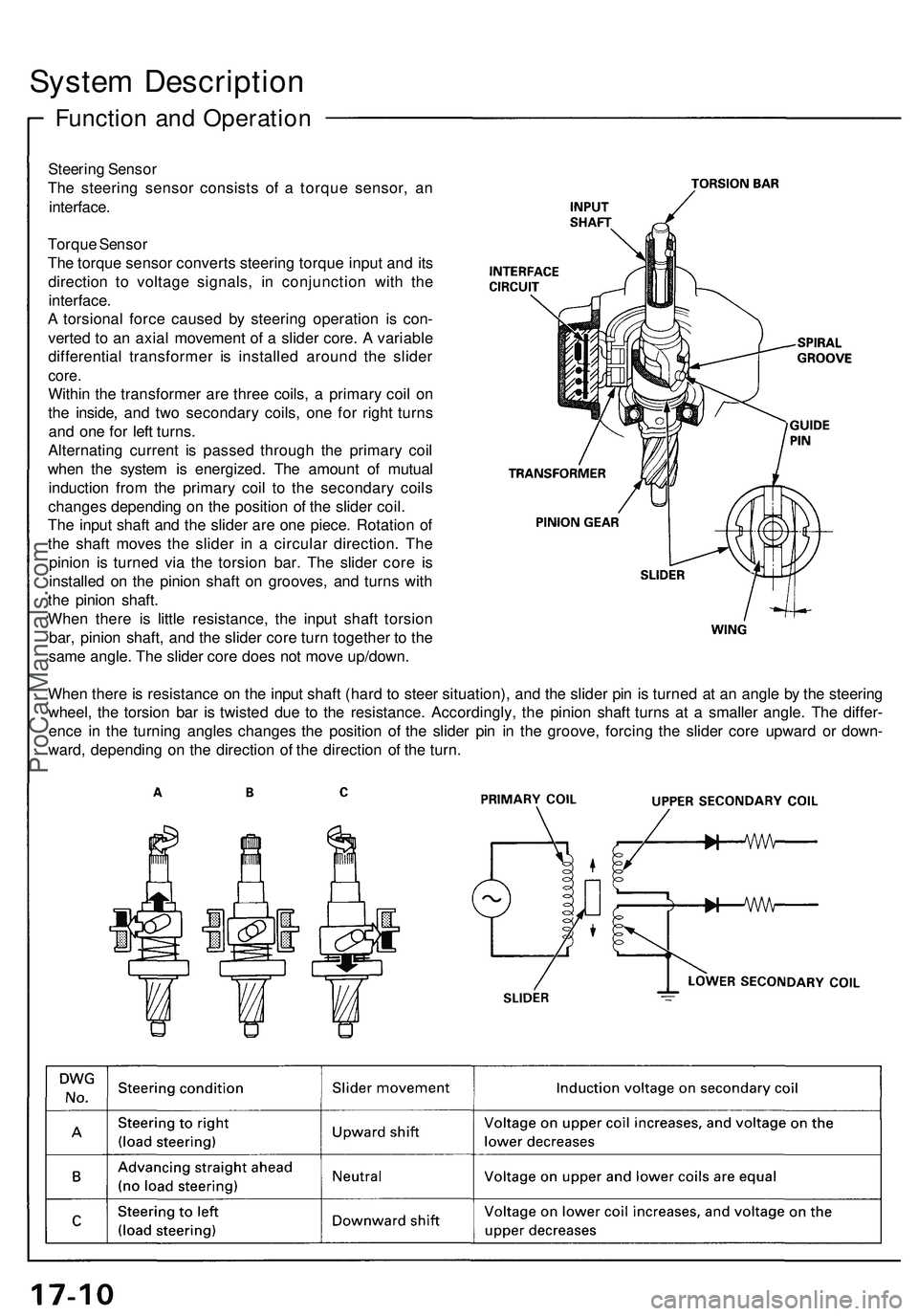
Steering Sensor
The steering sensor consists of a torque sensor, an
interface.
Torque Sensor
The torque sensor converts steering torque input and its
direction to voltage signals, in conjunction with the
interface.
A torsional force caused by steering operation is con-
verted to an axial movement of a slider core. A variable
differential transformer is installed around the slider
core.
Within the transformer are three coils, a primary coil on
the inside, and two secondary coils, one for right turns
and one for left turns.
Alternating current is passed through the primary coil
when the system is energized. The amount of mutual
induction from the primary coil to the secondary coils
changes depending on the position of the slider coil.
The input shaft and the slider are one piece. Rotation of
the shaft moves the slider in a circular direction. The
pinion is turned via the torsion bar. The slider core is
installed on the pinion shaft on grooves, and turns with
the pinion shaft.
When there is little resistance, the input shaft torsion
bar, pinion shaft, and the slider core turn together to the
same angle. The slider core does not move up/down.
When there is resistance on the input shaft (hard to steer situation), and the slider pin is turned at an angle by the steering
wheel, the torsion bar is twisted due to the resistance. Accordingly, the pinion shaft turns at a smaller angle. The differ-
ence in the turning angles changes the position of the slider pin in the groove, forcing the slider core upward or down-
ward, depending on the direction of the direction of the turn.ProCarManuals.com
Page 900 of 1503
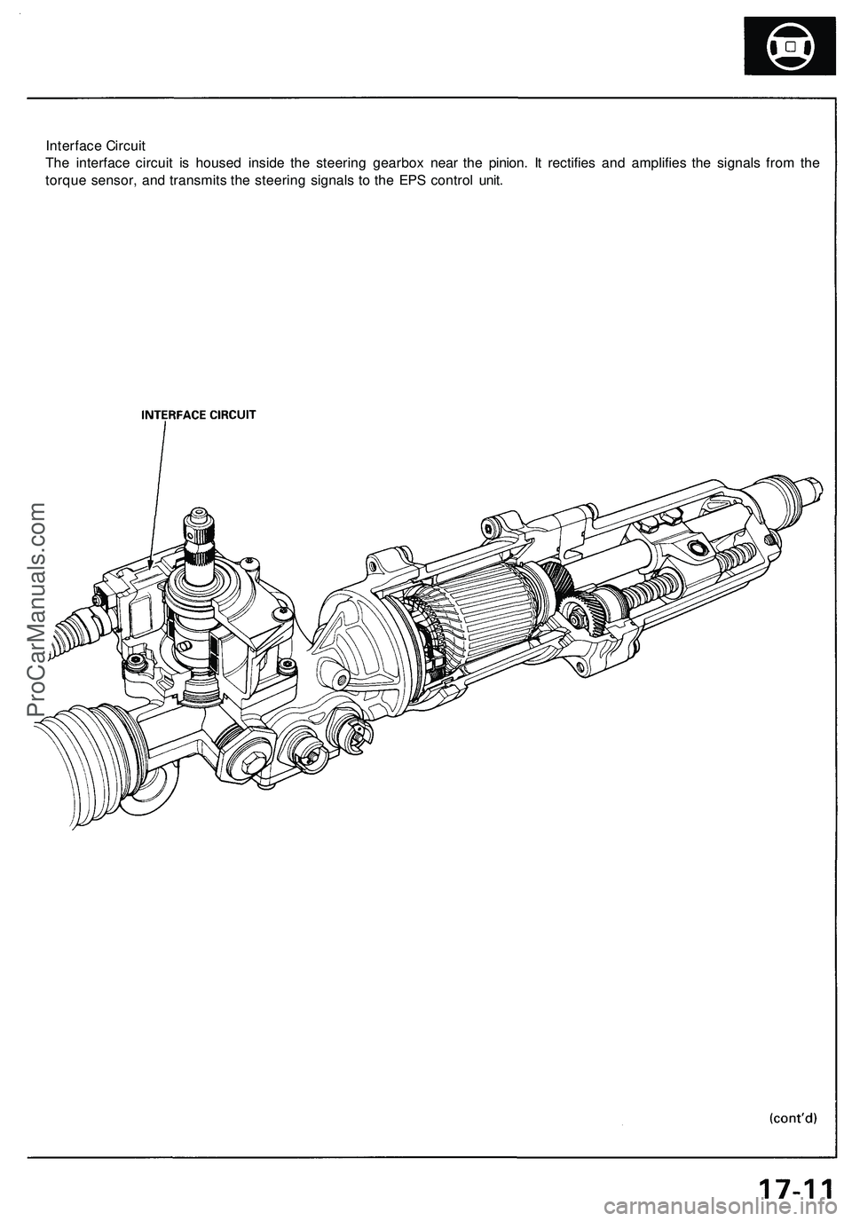
Interface Circuit
The interface circuit is housed inside the steering gearbox near the pinion. It rectifies and amplifies the signals from the
torque sensor, and transmits the steering signals to the EPS control unit.ProCarManuals.com