ACURA RL KA9 1996 Service Owner's Guide
Manufacturer: ACURA, Model Year: 1996, Model line: RL KA9, Model: ACURA RL KA9 1996Pages: 1954, PDF Size: 61.44 MB
Page 31 of 1954
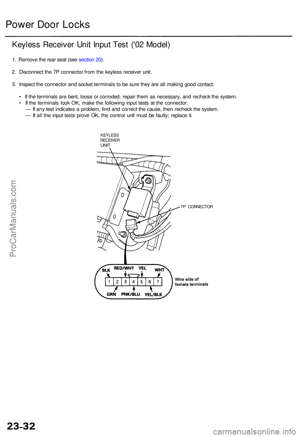
Power Doo r Lock s
Keyles s Receive r Uni t Inpu t Tes t ('0 2 Model )
1. Remov e th e rea r sea t (se e sectio n 20 ).
2 . Disconnec t th e 7 P connecto r fro m th e keyles s receive r unit .
3 . Inspec t th e connecto r an d socke t terminal s t o b e sur e the y ar e al l makin g goo d contact .
• I f th e terminal s ar e bent , loos e o r corroded , repai r the m a s necessary , an d rechec k th e system .
• I f th e terminal s loo k OK , mak e th e followin g inpu t test s a t th e connector .
— If an y tes t indicate s a problem , fin d an d correc t th e cause , the n rechec k th e system .
— If al l th e inpu t test s prov e OK , th e contro l uni t mus t b e faulty ; replac e it .
KEYLES SRECEIVE RUNIT
7P CONNECTO R
ProCarManuals.com
Page 32 of 1954
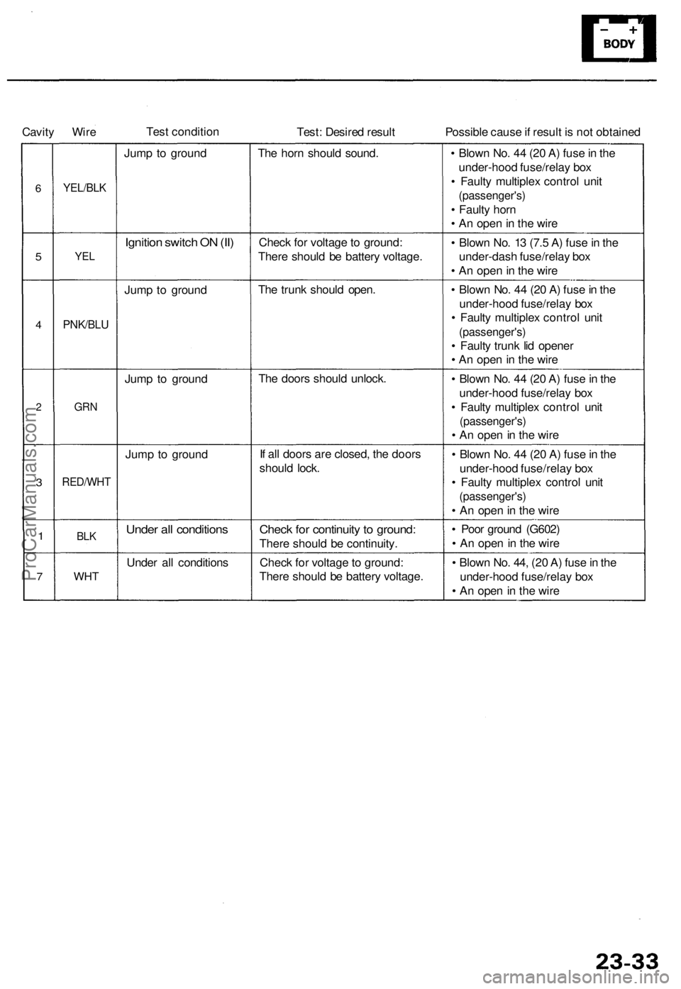
Cavity Wire
Test condition
Test: Desired result
Possible cause if result is not obtained
6
5
4
2
3
1
7
YEL/BLK
YEL
PNK/BLU
GRN
RED/WHT
BLK
WHT
Jump to ground
Ignition switch ON (II)
Jump to ground
Jump to ground
Jump to ground
Under all conditions
Under all conditions
The horn should sound.
Check for voltage to ground:
There should be battery voltage.
The trunk should open.
The doors should unlock.
If all doors are closed, the doors
should lock.
Check for continuity to ground:
There should be continuity.
Check for voltage to ground:
There should be battery voltage.
• Blown No. 44 (20 A) fuse in the
under-hood fuse/relay box
• Faulty multiplex control unit
(passenger's)
• Faulty horn
• An open in the wire
• Blown No. 13 (7.5 A) fuse in the
under-dash fuse/relay box
• An open in the wire
• Blown No. 44 (20 A) fuse in the
under-hood fuse/relay box
• Faulty multiplex control unit
(passenger's)
• Faulty trunk lid opener
• An open in the wire
• Blown No. 44 (20 A) fuse in the
under-hood fuse/relay box
• Faulty multiplex control unit
(passenger's)
• An open in the wire
• Blown No. 44 (20 A) fuse in the
under-hood fuse/relay box
• Faulty multiplex control unit
(passenger's)
• An open in the wire
• Poor ground (G602)
• An open in the wire
• Blown No. 44, (20 A) fuse in the
under-hood fuse/relay box
• An open in the wireProCarManuals.com
Page 33 of 1954
Power Doo r Lock s
Transmitte r Tes t ('0 2-04 Models )
NOTE:
• I f th e door s unloc k o r loc k wit h th e transmitter , bu t
th e LE D o n th e transmitte r doe s no t com e on , th e
LE D is faulty ; replac e th e transmitter .
• I f an y doo r i s open , yo u canno t loc k th e doo r wit h th e
transmitter .
• I f yo u unlocke d th e door s wit h th e transmitter , bu t d o
no t ope n an y o f th e door s withi n 3 0 seconds , th e
door s reloc k automatically .
• Th e door s d o no t loc k o r unloc k wit h th e transmitte r
if th e ignitio n ke y is inserte d in th e ignitio n switch .
• Fo r PANI C butto n an d TRUN K butto n operation , hol d
th e butto n lo r mor e tha n 1 second .
1 . Pres s th e loc k o r unloc k butto n fiv e o r si x time s t o
rese t th e transmitter .
• I f th e lock s work , th e transmitte r i s OK .
• I f th e lock s don' t work , g o to ste p 2 .
2 . Ope n th e transmitte r an d chec k fo r wate r damage .
• I f yo u fin d an y wate r damage , replac e th e trans -
mitter.
• I f ther e is n o wate r damage , g o to ste p 3 .
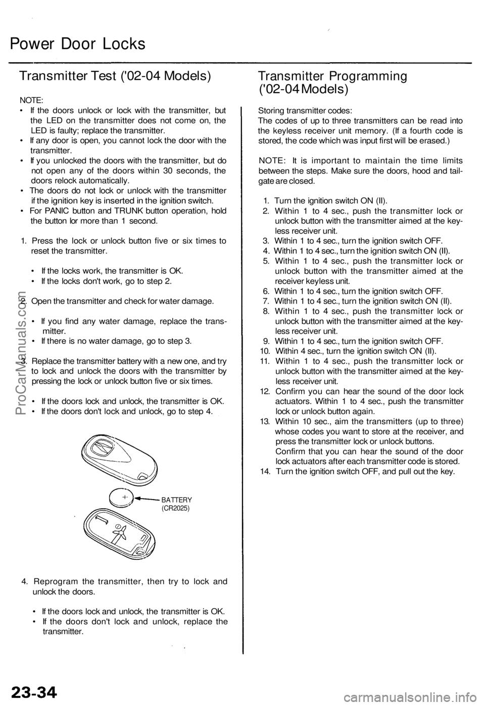
3 . Replac e th e transmitte r batter y wit h a ne w one , an d tr y
t o loc k an d unloc k th e door s wit h th e transmitte r b y
pressin g th e loc k o r unloc k butto n fiv e o r si x times .
• I f th e door s loc k an d unlock , th e transmitte r i s OK .
• I f th e door s don' t loc k an d unlock , g o to ste p 4 .
BATTER Y(CR2025)
4. Reprogra m th e transmitter , the n tr y t o loc k an d
unloc k th e doors .
• I f th e door s loc k an d unlock , th e transmitte r i s OK .
• I f th e door s don' t loc k an d unlock , replac e th e
transmitter .
Transmitte r Programmin g
('02-04 Models )
Storing transmitte r codes :
Th e code s o f u p t o thre e transmitter s ca n b e rea d int o
th e keyles s receive r uni t memory . (I f a fourt h cod e i s
stored , th e cod e whic h wa s inpu t firs t wil l b e erased. )
NOTE : I t i s importan t t o maintai n th e tim e limit s
betwee n th e steps . Mak e sur e th e doors , hoo d an d tail -
gat e ar e closed .
1 . Tur n th e ignitio n switc h O N (II) .
2 . Withi n 1 to 4 sec. , pus h th e transmitte r loc k o r
unloc k butto n wit h th e transmitte r aime d a t th e key -
les s receive r unit .
3 . Withi n 1 to 4 sec. , tur n th e ignitio n switc h OFF .
4. Withi n 1 to 4 sec. , tur n th e ignitio n switc h O N (II) .
5. Withi n 1 to 4 sec. , pus h th e transmitte r loc k o r
unloc k butto n with the transmitte r aime d a t th e
receive r keyles s unit .
6 . Withi n 1 to 4 sec. , tur n th e ignitio n switc h OFF .
7 . Withi n 1 to 4 sec. , tur n th e ignitio n switc h O N (II) .
8 . Withi n 1 to 4 sec. , pus h th e transmitte r loc k o r
unloc k butto n wit h th e transmitte r aime d a t th e key -
les s receive r unit .
9 . Withi n 1 to 4 sec. , tur n th e ignitio n switc h OFF .
10 . Withi n 4 sec. , tur n th e ignitio n switc h O N (II) .
11 . Withi n 1 to 4 sec. , pus h th e transmitte r loc k o r
unloc k butto n wit h th e transmitte r aime d a t th e key -
les s receive r unit .
12 . Confir m yo u ca n hea r th e soun d o f th e doo r loc k
actuators . Withi n 1 to 4 sec. , pus h th e transmitte r
loc k o r unloc k butto n again .
13 . Withi n 1 0 sec. , ai m th e transmitter s (u p t o three )
whos e code s yo u wan t t o stor e a t th e receiver , an d
pres s th e transmitte r loc k o r unloc k buttons .
Confir m tha t yo u can hea r th e soun d o f th e doo r
loc k actuator s afte r eac h transmitte r cod e is stored .
14 . Tur n th e ignitio n switc h OFF , an d pul l ou t th e key .
ProCarManuals.com
Page 34 of 1954
Power Windows
Component Location Index
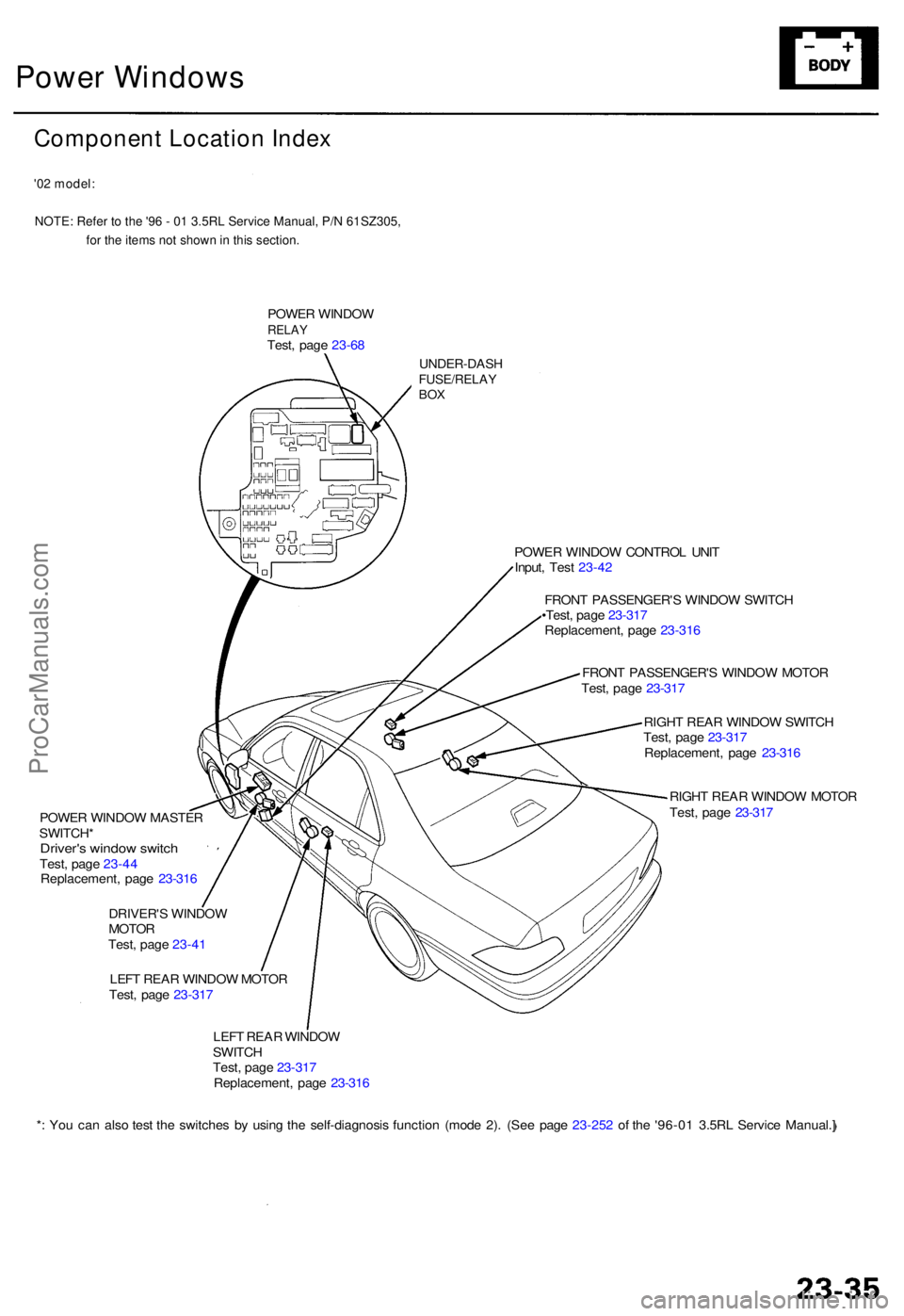
'02 model:NOTE: Refer to the '96 - 01 3.5RL Service Manual, P/N 61SZ305, for the items not shown in this section.
POWER WINDO WRELAYTest, pag e 23-6 8
UNDER-DAS HFUSE/RELAYBOX
POWE R WINDO W MASTE R
SWITCH *
Driver's windo w switc hTest, pag e 23-4 4
Replacement , pag e 23-31 6
DRIVER' S WINDO W
MOTO R
Test , pag e 23-4 1
LEF T REA R WINDO W MOTO R
Test , pag e 23-31 7 POWE
R WINDO W CONTRO L UNI T
Input , Tes t 23-4 2
FRON T PASSENGER' S WINDO W SWITC H
•Test , pag e 23-31 7
Replacement , pag e 23-31 6
FRON T PASSENGER' S WINDO W MOTO R
Test , pag e 23-31 7
RIGH T REA R WINDO W SWITC H
Test , pag e 23-31 7
Replacement , pag e 23-31 6
RIGH T REA R WINDO W MOTO R
Test , pag e 23-31 7
LEF T REA R WINDO W
SWITC H
Test , pag e 23-31 7
Replacement , pag e 23-31 6
* : Yo u ca n als o tes t th e switche s b y usin g th e self-diagnosi s functio n (mod e 2) . (Se e pag e 23-25 2 o f th e '96-0 1 3.5R L Servic e Manual. ]
ProCarManuals.com
Page 35 of 1954
Power Window s
Description s
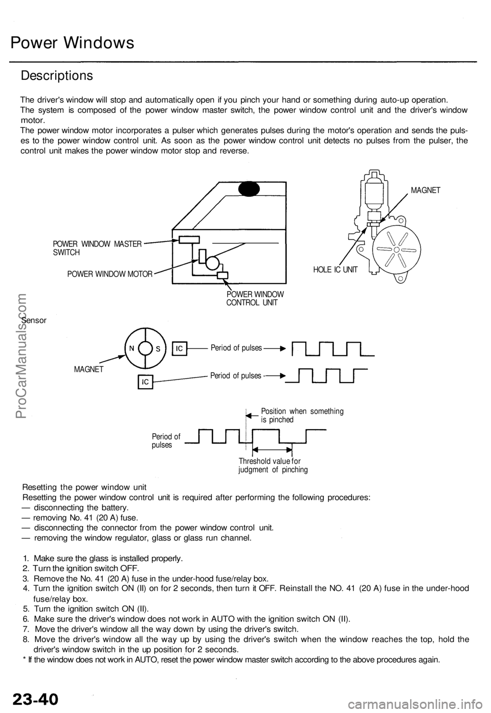
The driver' s windo w wil l sto p an d automaticall y ope n i f yo u pinc h you r han d o r somethin g durin g auto-u p operation .
Th e syste m is compose d o f th e powe r windo w maste r switch , th e powe r windo w contro l uni t an d th e driver' s windo w
motor.
The powe r windo w moto r incorporate s a pulse r whic h generate s pulse s durin g th e motor' s operatio n an d send s th e puls -
e s t o th e powe r windo w contro l unit . As soo n a s th e powe r windo w contro l uni t detect s n o pulse s fro m th e pulser , th e
contro l uni t make s th e powe r windo w moto r sto p an d reverse .
POWER WINDO W MASTE R
SWITC H
POWE R WINDO W MOTO R HOL
E IC UNI T MAGNE
T
POWE R WINDO W
CONTRO L UNI T
Senso r
MAGNE T
Period o f pulse s -
Perio d o f
pulse s Positio
n whe n somethin g
i s pinche d
Threshol d valu e fo r
judgmen t o f pinchin g
Resettin g th e powe r windo w uni t
Resettin g th e powe r windo w contro l uni t i s require d afte r performin g th e followin g procedures :
— disconnectin g th e battery .
— removin g No . 4 1 (2 0 A ) fuse .
— disconnectin g th e connecto r fro m th e powe r windo w contro l unit .
— removin g th e windo w regulator , glas s o r glas s ru n channel .
1. Mak e sur e th e glas s is installe d properly .
2. Tur n th e ignitio n switc h OFF .
3. Remov e th e No . 4 1 (2 0 A ) fus e in th e under-hoo d fuse/rela y box .
4 . Tur n th e ignitio n switc h O N (II ) o n fo r 2 seconds , the n tur n it OFF . Reinstal l th e NO . 4 1 (2 0 A ) fus e in th e under-hoo d
fuse/rela y box .
5 . Tur n th e ignitio n switc h O N (II) .
6 . Mak e sur e th e driver' s windo w doe s no t wor k in AUT O wit h th e ignitio n switc h O N (II) .
7 . Mov e th e driver' s windo w al l th e wa y dow n b y usin g th e driver' s switch .
8 . Mov e th e driver' s windo w al l th e wa y u p b y usin g th e driver' s switc h whe n th e windo w reache s th e top , hol d th e
driver' s windo w switc h in th e u p positio n fo r 2 seconds .
* I f th e windo w doe s no t wor k in AUTO , rese t th e powe r windo w maste r switc h accordin g to th e abov e procedure s again .
Period o f pulse s
ProCarManuals.com
Page 36 of 1954
Driver's Windo w Moto r Tes t ('0 2-04 Models )
Motor Test :
1 . Remov e th e driver' s doo r panel .
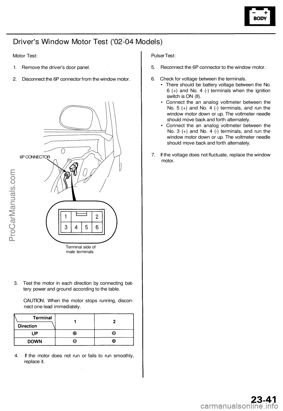
2 . Disconnec t th e 6 P connecto r fro m th e windo w motor .
6P CONNECTO R
Terminal sid e o f
mal e terminal s
3. Tes t th e moto r i n eac h directio n b y connectin g bat -
ter y powe r an d groun d accordin g to th e table .
CAUTION : Whe n th e moto r stop s running , discon -
nec t on e lea d immediately .
4 . I f th e moto r doe s no t ru n o r fail s t o ru n smoothly ,
replac e it . Pulse
r Test :
5 . Reconnec t th e 6 P connecto r t o th e windo w motor .
6 . Chec k fo r voltag e betwee n th e terminals .
• Ther e shoul d b e batter y voltag e betwee n th e No .
6 (+ ) an d No . 4 (- ) terminal s whe n th e ignitio n
switc h is O N (II) .
• Connec t th e a n analo g voltmete r betwee n th e
No . 5 (+ ) an d No . 4 (- ) terminals , an d ru n th e
windo w moto r dow n o r up . Th e voltmete r needl e
shoul d mov e bac k an d fort h alternately .
• Connec t th e a n analo g voltmete r betwee n th e
No . 3 (+ ) an d No . 4 (- ) terminals , an d ru n th e
windo w moto r dow n o r up . Th e voltmete r needl e
shoul d mov e bac k an d fort h alternately .
7 . I f th e voltag e doe s no t fluctuate , replac e th e windo w
motor.
ProCarManuals.com
Page 37 of 1954
Power Window s
Control Uni t Inpu t Tes t
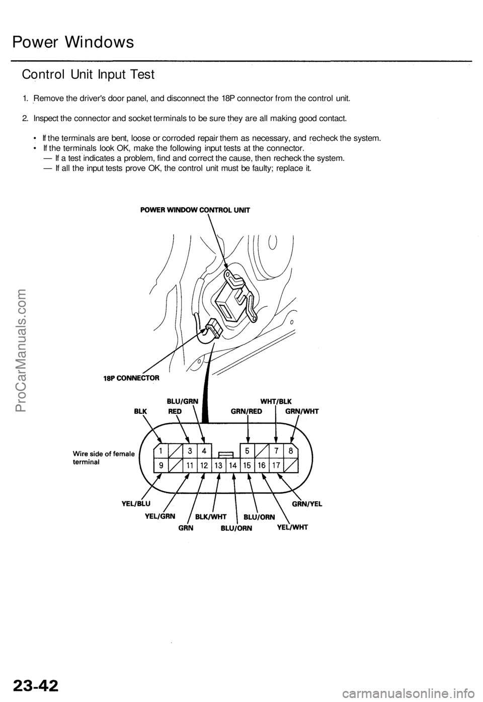
1. Remov e th e driver' s doo r panel , an d disconnec t th e 18 P connecto r fro m th e contro l unit .
2 . Inspec t th e connecto r an d socke t terminal s t o b e sur e the y ar e al l makin g goo d contact .
• I f th e terminal s ar e bent , loos e o r corrode d repai r the m a s necessary , an d rechec k th e system .
• I f th e terminal s loo k OK , mak e th e followin g inpu t test s a t th e connector .
— If a tes t indicate s a problem , fin d an d correc t th e cause , the n rechec k th e system .
— If al l th e inpu t test s prov e OK , th e contro l uni t mus t b e faulty ; replac e it .
ProCarManuals.com
Page 38 of 1954
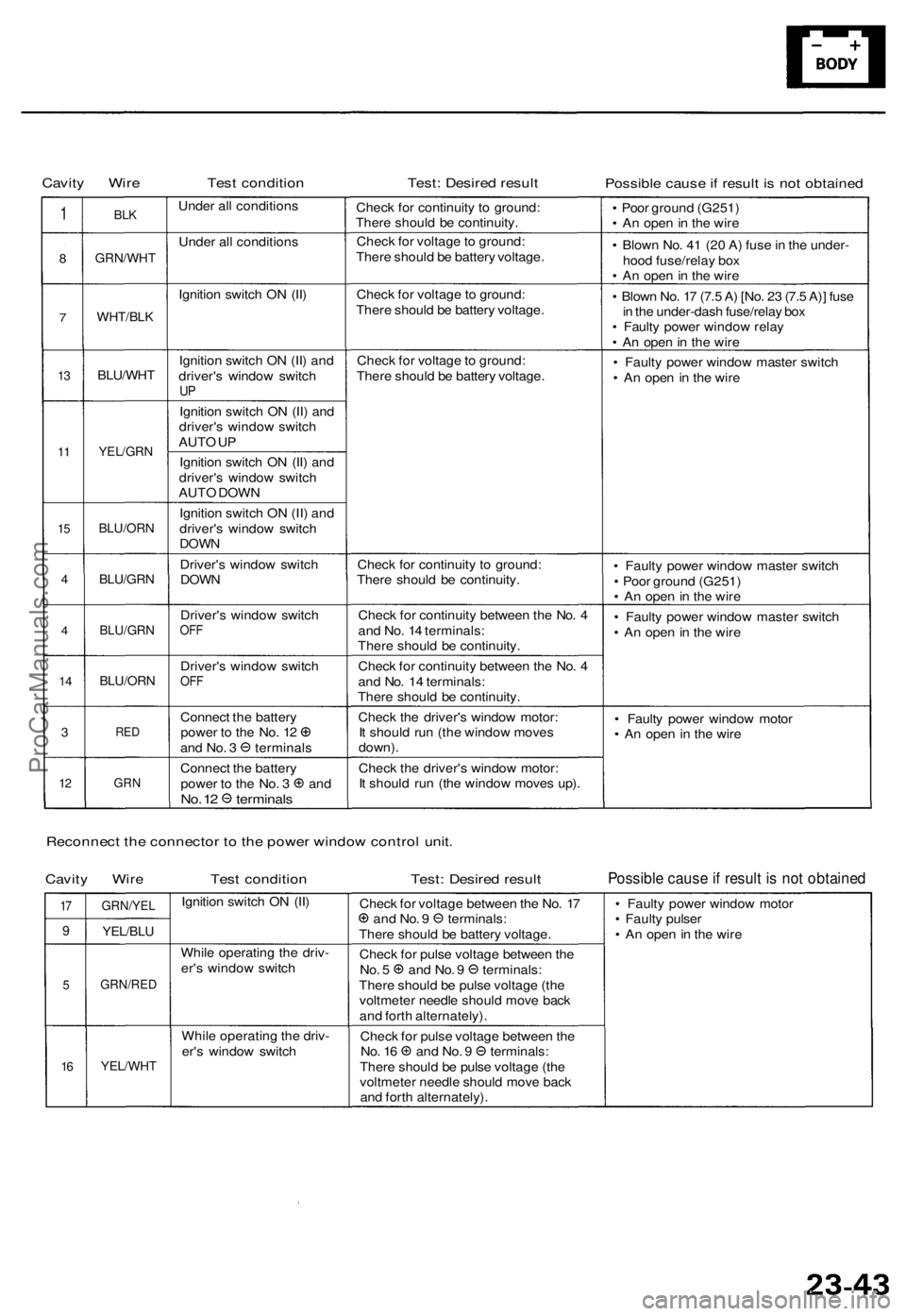
Cavity Wir eTest conditio nTest: Desire d resul tPossibl e caus e if resul t i s no t obtaine d
1
8
7
13
1 1
1 5
4
4
1 4
3
12
BL K
GRN/WH T
WHT/BLK
BLU/WH T
YEL/GRN
BLU/OR N
BLU/GRN
BLU/GR N
BLU/ORN
RED
GR N
Unde r al l condition s
Unde r al l condition s
Ignitio n switc h O N (II )
Ignitio n switc h O N (II ) an d
driver' s windo w switc h
UP
Ignitio n switc h O N (II ) an d
driver' s windo w switc h
AUT O U P
Ignitio n switc h O N (II ) an d
driver' s windo w switc h
AUT O DOW N
Ignitio n switc h O N (II ) an d
driver' s windo w switc h
DOWN
Driver' s windo w switc hDOWN
Driver' s windo w switc hOFF
Driver' s windo w switc hOFF
Connec t th e batter ypower t o th e No . 1 2an d No . 3 terminal s
Connec t th e batter y
power t o th e No . 3 an dNo. 1 2 terminal s
Check fo r continuit y t o ground :
Ther e shoul d b e continuity .
Chec k fo r voltag e to ground :
Ther e shoul d b e batter y voltage .
Chec k fo r voltag e to ground :
Ther e shoul d b e batter y voltage .
Chec k fo r voltag e to ground :
Ther e shoul d b e batter y voltage .
Chec k fo r continuit y t o ground :
Ther e shoul d b e continuity .
Chec k fo r continuit y betwee n th e No . 4
an d No . 1 4 terminals :
Ther e shoul d b e continuity .
Chec k fo r continuit y betwee n th e No . 4
an d No . 1 4 terminals :
Ther e shoul d b e continuity .
Chec k th e driver' s windo w motor :
I t shoul d ru n (th e windo w move s
down) .
Chec k th e driver' s windo w motor :
I t shoul d ru n (th e windo w move s up) . •
Poo r groun d (G251 )
• A n ope n in th e wir e
• Blow n No . 4 1 (2 0 A ) fus e in th e under -
hoo d fuse/rela y bo x
• A n ope n in th e wir e
• Blow n No . 1 7 (7. 5 A ) [No . 2 3 (7. 5 A) ] fus e
i n th e under-das h fuse/rela y bo x
• Fault y powe r windo w rela y
• A n ope n in th e wir e
• Fault y powe r windo w maste r switc h
• A n ope n in th e wire
• Fault y powe r windo w maste r switc h
• Poo r groun d (G251 )
• A n ope n in th e wir e
• Fault y powe r windo w maste r switc h
• A n ope n in th e wir e
• Fault y powe r windo w moto r
• A n ope n in th e wir e
Reconnec t th e connecto r t o th e powe r windo w contro l unit .
Cavit y Wir eTest conditio nTest: Desire d resul tPossibl e caus e if resul t i s no t obtaine d
17
9
5
16
GRN/YE L
YEL/BLU
GRN/RE D
YEL/WHT
Ignition switc h O N (II )
Whil e operatin g th e driv -
er' s windo w switc h
Whil e operatin g th e driv -
er' s windo w switc h Chec
k fo r voltag e betwee n th e No . 1 7
an d No . 9 terminals :
Ther e shoul d b e batter y voltage .
Chec k fo r puls e voltag e betwee n th e
No . 5 an d No . 9 terminals :
Ther e shoul d b e puls e voltag e (th e
voltmete r needl e shoul d mov e bac k
an d fort h alternately) .
Chec k fo r puls e voltag e betwee n th e
No . 1 6 an d No . 9 terminals :
Ther e shoul d b e puls e voltag e (th e
voltmete r needl e shoul d mov e bac k
an d fort h alternately) . •
Fault y powe r windo w moto r
• Fault y pulse r
• A n ope n in th e wir e
ProCarManuals.com
Page 39 of 1954
Power Windows
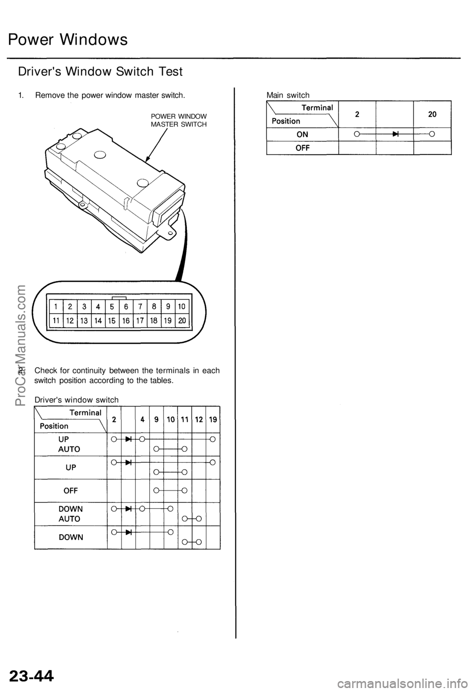
Driver's Window Switch Test
1. Remove the power window master switch.
POWER WINDOW
MASTER SWITCH
2. Check for continuity between the terminals in each
switch position according to the tables.
Driver's window switch
Main switchProCarManuals.com
Page 40 of 1954
Automatic Insid e Dimmin g Mirro r
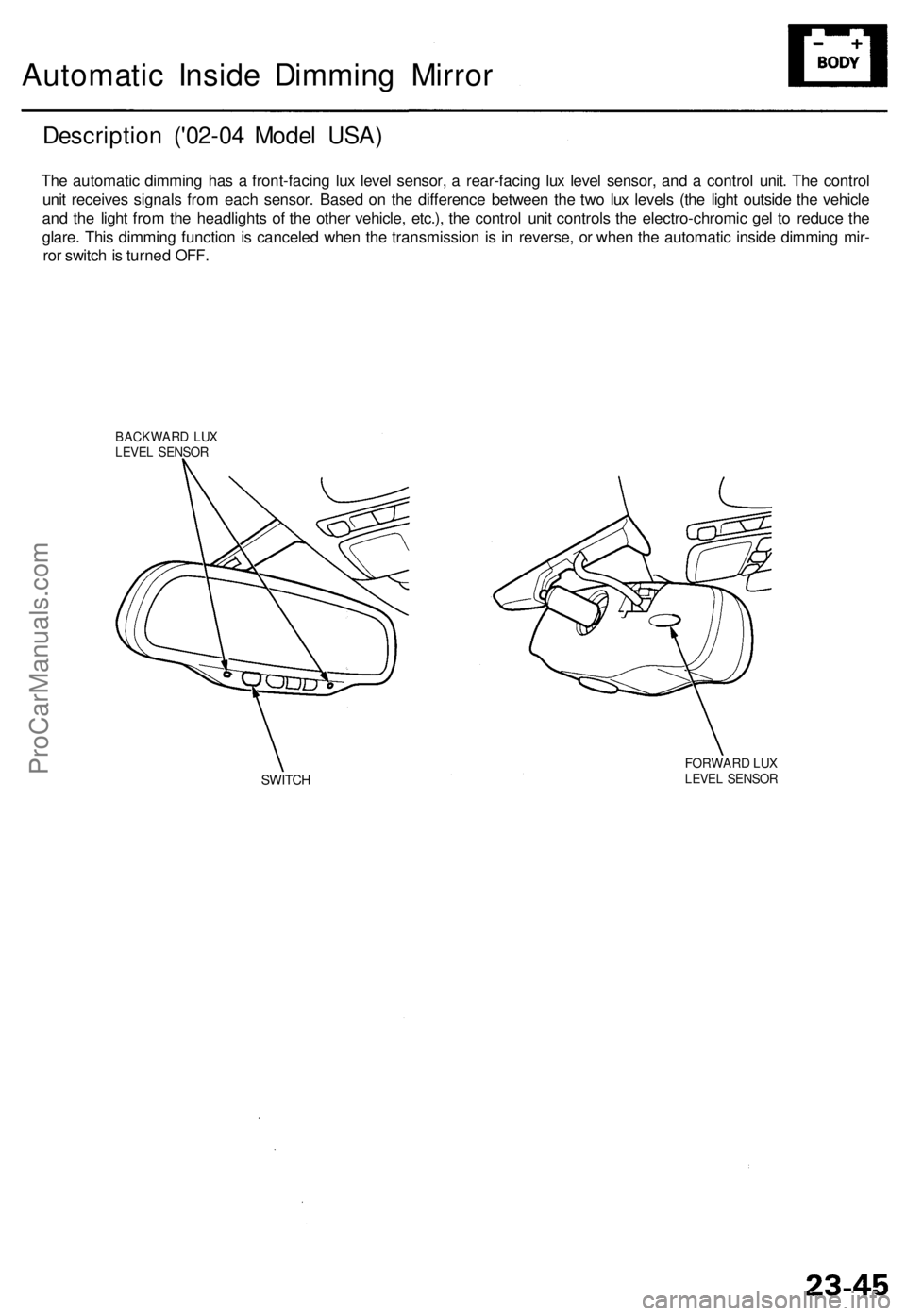
Descriptio n ('0 2-04 Mode l USA )
The automati c dimmin g ha s a front-facin g lu x leve l sensor , a rear-facin g lu x leve l sensor , an d a contro l unit . Th e contro l
uni t receive s signal s fro m eac h sensor . Base d o n th e differenc e betwee n th e tw o lu x level s (th e ligh t outsid e th e vehicl e
an d th e ligh t fro m th e headlight s o f th e othe r vehicle , etc.) , th e contro l uni t control s th e electro-chromi c ge l t o reduc e th e
glare . Thi s dimmin g functio n is cancele d whe n th e transmissio n i s i n reverse , o r whe n th e automati c insid e dimmin g mir -
ro r switc h is turne d OFF .
BACKWAR D LU XLEVE L SENSO R
SWITCHFORWAR D LU XLEVE L SENSO R
ProCarManuals.com