ACURA RL KA9 1996 Service Workshop Manual
Manufacturer: ACURA, Model Year: 1996, Model line: RL KA9, Model: ACURA RL KA9 1996Pages: 1954, PDF Size: 61.44 MB
Page 51 of 1954
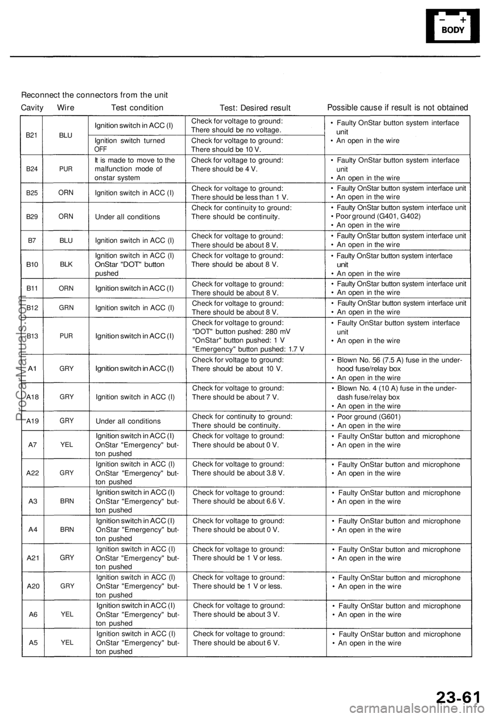
Reconnect the connectors from the unit
Cavity Wire Test condition
Test: Desired result
Possible cause if result is not obtained
B21
B24
B25
B29
B7
B10
B11
B12
B13
A1
A18
A19
A7
A22
A3
A4
A21
A20
A6
A5
BLU
PUR
ORN
ORN
BLU
BLK
ORN
GRN
PUR
GRY
GRY
GRY
YEL
GRY
BRN
BRN
GRY
GRY
YEL
YEL
Ignition switch in ACC (I)
Ignition switch turned
OFF
It is made to move to the
malfunction mode of
onstar system
Ignition switch in ACC (I)
Under all conditions
Ignition switch in ACC (I)
Ignition switch in ACC (I)
OnStar "DOT" button
pushed
Ignition switch in ACC (I)
Ignition switch in ACC (I)
Ignition switch in ACC (I)
Ignition switch in ACC (I)
Ignition switch in ACC (I)
Under all conditions
Ignition switch in ACC (I)
OnStar "Emergency" but-
ton pushed
Ignition switch in ACC (I)
OnStar "Emergency" but-
ton pushed
Ignition switch in ACC (I)
OnStar "Emergency" but-
ton pushed
Ignition switch in ACC (I)
OnStar "Emergency" but-
ton pushed
Ignition switch in ACC (I)
OnStar "Emergency" but-
ton pushed
Ignition switch in ACC (I)
OnStar "Emergency" but-
ton pushed
Ignition switch in ACC (I)
OnStar "Emergency" but-
ton pushed
Ignition switch in ACC (I)
OnStar "Emergency" but-
ton pushed
Check for voltage to ground:
There should be no voltage.
Check for voltage to ground:
There should be 10 V.
Check for voltage to ground:
There should be 4 V.
Check for voltage to ground:
There should be less than 1 V.
Check for continuity to ground:
There should be continuity.
Check for voltage to ground:
There should be about 8 V.
Check for voltage to ground:
There should be about 8 V.
Check for voltage to ground:
There should be about 8 V.
Check for voltage to ground:
There should be about 8 V.
Check for voltage to ground:
"DOT" button pushed: 280 mV
"OnStar" button pushed: 1 V
"Emergency" button pushed: 1.7 V
Check for voltage to ground:
There should be about 10 V.
Check for voltage to ground:
There should be about 7 V.
Check for continuity to ground:
There should be continuity.
Check for voltage to ground:
There should be about 0 V.
Check for voltage to ground:
There should be about 3.8 V.
Check for voltage to ground:
There should be about 6.6 V.
Check for voltage to ground:
There should be about 0 V.
Check for voltage to ground:
There should be 1 V or less.
Check for voltage to ground:
There should be 1 V or less.
Check for voltage to ground:
There should be about 3 V.
Check for voltage to ground:
There should be about 6 V.
• Faulty OnStar button system interface
unit
• An open in the wire
• Faulty OnStar button system interface
unit
• An open in the wire
• Faulty OnStar button system interface unit
• An open in the wire
• Faulty OnStar button system interface unit
• Poor ground (G401, G402)
• An open in the wire
• Faulty OnStar button system interface unit
• An open in the wire
• Faulty OnStar button system interface
unit
• An open in the wire
• Faulty OnStar button system interface unit
• An open in the wire
• Faulty OnStar button system interface unit
• An open in the wire
• Faulty OnStar button system interface
unit
• An open in the wire
• Blown No. 56 (7.5 A) fuse in the under-
hood fuse/relay box
• An open in the wire
• Blown No. 4 (10 A) fuse in the under-
dash fuse/relay box
• An open in the wire
• Poor ground (G601)
• An open in the wire
• Faulty OnStar button and microphone
• An open in the wire
• Faulty OnStar button and microphone
• An open in the wire
• Faulty OnStar button and microphone
• An open in the wire
• Faulty OnStar button and microphone
• An open in the wire
• Faulty OnStar button and microphone
• An open in the wire
• Faulty OnStar button and microphone
• An open in the wire
• Faulty OnStar button and microphone
• An open in the wire
• Faulty OnStar button and microphone
• An open in the wireProCarManuals.com
Page 52 of 1954
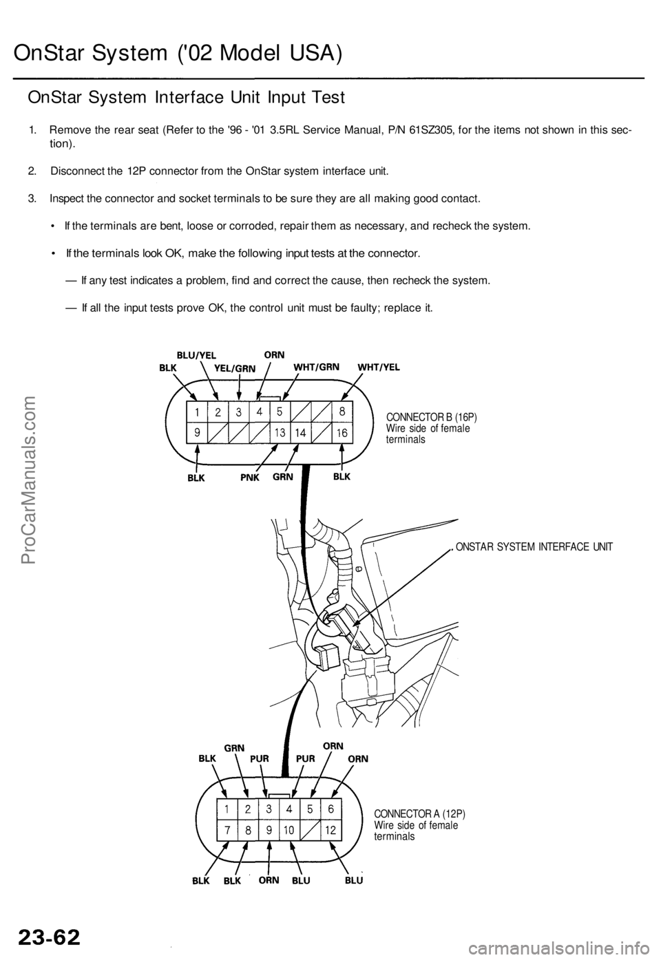
OnStar Syste m ('0 2 Mode l USA )
OnSta r Syste m Interfac e Uni t Inpu t Tes t
1. Remov e th e rea r sea t (Refe r t o th e '9 6 - '0 1 3.5R L Servic e Manual , P/ N 61SZ305 , fo r th e item s no t show n i n thi s sec -
tion) .
2. Disconnec t th e 12 P connecto r fro m th e OnSta r syste m interfac e unit .
3 . Inspec t th e connecto r an d socke t terminal s t o b e sur e the y ar e al l makin g goo d contact .
• I f th e terminal s ar e bent , loos e o r corroded , repai r the m a s necessary , an d rechec k th e system .
• I f th e terminal s loo k OK , mak e th e followin g inpu t test s a t th e connector .
— If an y tes t indicate s a problem , fin d an d correc t th e cause , the n rechec k th e system .
— If al l th e inpu t test s prov e OK , th e contro l uni t mus t b e faulty ; replac e it .
CONNECTO R B (16P )
Wir e sid e o f femal e
terminal s
CONNECTO R A (12P )
Wir e sid e o f femal e
terminal s
. ONSTA R SYSTE M INTERFAC E UNI T
ProCarManuals.com
Page 53 of 1954
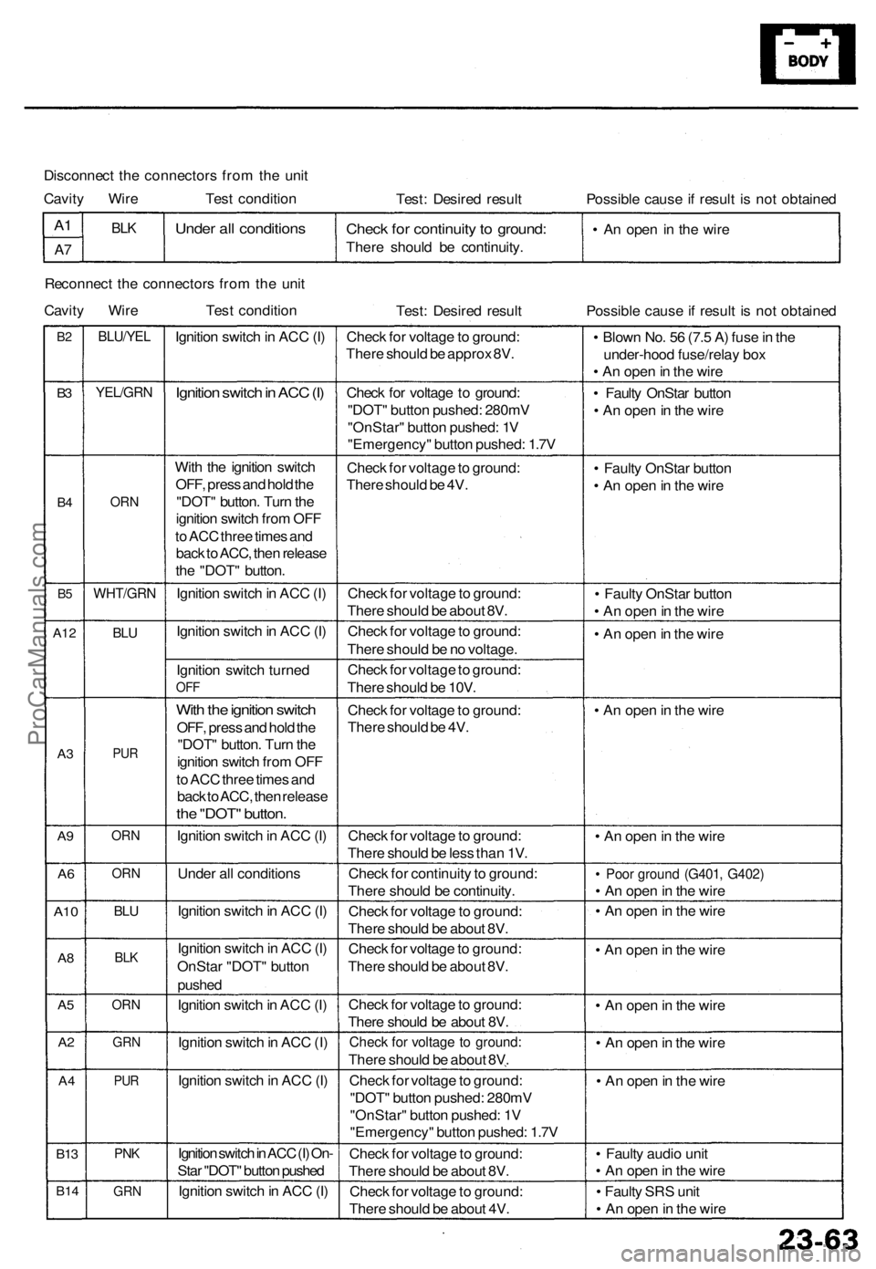
Disconnect the connectors from the unit
Cavity Wire Test condition
Test: Desired result
Possible cause if result is not obtained
A1
A7
BLK
Under all conditions
Check for continuity to ground:
There should be continuity.
• An open in the wire
Reconnect the connectors from the unit
Cavity Wire Test condition
Test: Desired result
Possible cause if result is not obtained
B2
B3
B4
B5
A12
A3
A9
A6
A10
A8
A5
A2
A4
B13
B14
BLU/YEL
YEL/GRN
ORN
WHT/GRN
BLU
PUR
ORN
ORN
BLU
BLK
ORN
GRN
PUR
PNK
GRN
Ignition switch in ACC (I)
Ignition switch in ACC (I)
With the ignition switch
OFF, press and hold the
"DOT" button. Turn the
ignition switch from OFF
to ACC three times and
back to ACC, then release
the "DOT" button.
Ignition switch in ACC (I)
Ignition switch in ACC (I)
Ignition switch turned
OFF
With the ignition switch
OFF, press and hold the
"DOT" button. Turn the
ignition switch from OFF
to ACC three times and
back to ACC, then release
the "DOT" button.
Ignition switch in ACC (I)
Under all conditions
Ignition switch in ACC (I)
Ignition switch in ACC (I)
OnStar "DOT" button
pushed
Ignition switch in ACC (I)
Ignition switch in ACC (I)
Ignition switch in ACC (I)
Ignition switch in ACC (I) On-
Star "DOT" button pushed
Ignition switch in ACC (I)
Check for voltage to ground:
There should be approx 8V.
Check for voltage to ground:
"DOT" button pushed: 280mV
"OnStar" button pushed: 1V
"Emergency" button pushed: 1.7V
Check for voltage to ground:
There should be 4V.
Check for voltage to ground:
There should be about 8V.
Check for voltage to ground:
There should be no voltage.
Check for voltage to ground:
There should be 10V.
Check for voltage to ground:
There should be 4V.
Check for voltage to ground:
There should be less than 1V.
Check for continuity to ground:
There should be continuity.
Check for voltage to ground:
There should be about 8V.
Check for voltage to ground:
There should be about 8V.
Check for voltage to ground:
There should be about 8V.
Check for voltage to ground:
There should be about 8V.
Check for voltage to ground:
"DOT" button pushed: 280mV
"OnStar" button pushed: 1V
"Emergency" button pushed: 1.7V
Check for voltage to ground:
There should be about 8V.
Check for voltage to ground:
There should be about 4V.
• Blown No. 56 (7.5 A) fuse in the
under-hood fuse/relay box
• An open in the wire
• Faulty OnStar button
• An open in the wire
• Faulty OnStar button
• An open in the wire
• Faulty OnStar button
• An open in the wire
• An open in the wire
• An open in the wire
• An open in the wire
• Poor ground (G401, G402)
• An open in the wire
• An open in the wire
• An open in the wire
• An open in the wire
• An open in the wire
• An open in the wire
• Faulty audio unit
• An open in the wire
• Faulty SRS unit
• An open in the wireProCarManuals.com
Page 54 of 1954
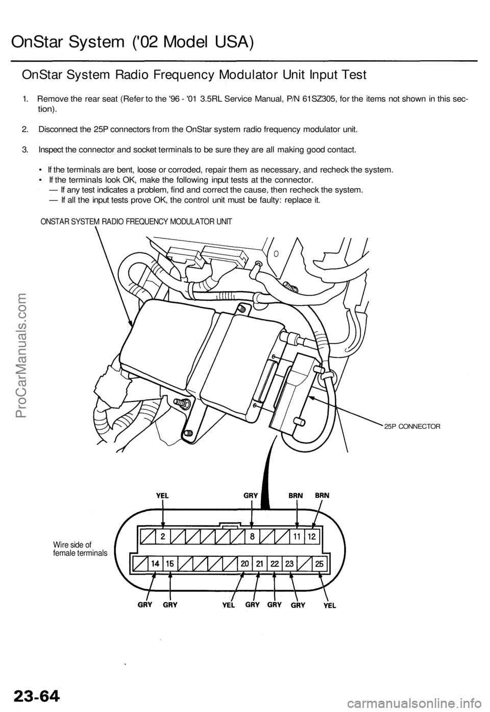
OnStar Syste m ('0 2 Mode l USA )
OnSta r Syste m Radi o Frequenc y Modulato r Uni t Inpu t Tes t
1. Remov e th e rea r sea t (Refe r t o th e '9 6 - '0 1 3.5R L Servic e Manual , P/ N 61SZ305 , fo r th e item s no t show n in thi s sec -
tion) .
2. Disconnec t th e 25 P connector s fro m th e OnSta r syste m radi o frequenc y modulato r unit .
3 . Inspec t th e connecto r an d socke t terminal s to b e sur e the y ar e al l makin g goo d contact .
• I f th e terminal s ar e bent , loos e o r corroded , repai r the m a s necessary , an d rechec k th e system .
• I f th e terminal s loo k OK , mak e th e followin g inpu t test s a t th e connector .
— If an y tes t indicate s a problem , fin d an d correc t th e cause , the n rechec k th e system .
— If al l th e inpu t test s prov e OK , th e contro l uni t mus t b e faulty : replac e it .
ONSTA R SYSTE M RADI O FREQUENC Y MODULATO R UNI T
Wire sid e o ffemal e terminal s
25P CONNECTO R
ProCarManuals.com
Page 55 of 1954
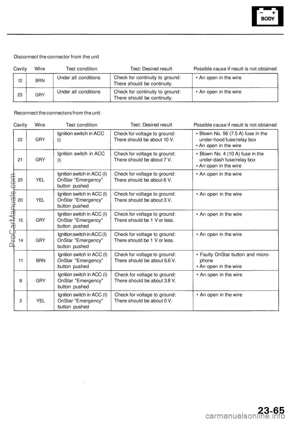
Disconnect the connector from the unit
Cavity Wire Test condition
Test: Desired result
Possible cause if result is not obtained
12
23
BRN
GRY
Under all conditions
Under all conditions
Check for continuity to ground:
There should be continuity.
Check for continuity to ground:
There should be continuity.
• An open in the wire
• An open in the wire
Reconnect the connectors from the unit
Cavity Wire Test condition
Test: Desired result
Possible cause if result is not obtained
22
21
25
20
15
14
11
8
2
GRY
GRY
YEL
YEL
GRY
GRY
BRN
GRY
YEL
Ignition switch in ACC
(I)
Ignition switch in ACC
(I)
Ignition switch in ACC (I)
OnStar "Emergency"
button pushed
Ignition switch in ACC (I)
OnStar "Emergency"
button pushed
Ignition switch in ACC (I)
OnStar "Emergency"
button pushed
Ignition switch in ACC (I)
OnStar "Emergency"
button pushed
Ignition switch in ACC (I)
OnStar "Emergency"
button pushed
Ignition switch in ACC (I)
OnStar "Emergency"
button pushed
Ignition switch in ACC (I)
OnStar "Emergency"
button pushed
Check for voltage to ground:
There should be about 10 V.
Check for voltage to ground:
There should be about 7 V.
Check for voltage to ground:
There should be about 6 V.
Check for voltage to ground:
There should be about 3 V.
Check for voltage to ground:
There should be 1 V or less.
Check for voltage to ground:
There should be 1 V or less.
Check for voltage to ground:
There should be about 6.6 V.
Check for voltage to ground:
There should be about 3.8 V.
Check for voltage to ground:
There should be about 0 V.
• Blown No. 56 (7.5 A) fuse in the
under-hood fuse/relay box
• An open in the wire
• Blown No. 4 (10 A) fuse in the
under-dash fuse/relay box
• An open in the wire
• An open in the wire
• An open in the wire
• An open in the wire
• An open in the wire
• Faulty OnStar button and micro-
phone
• An open in the wire
• An open in the wire
• An open in the wireProCarManuals.com
Page 56 of 1954
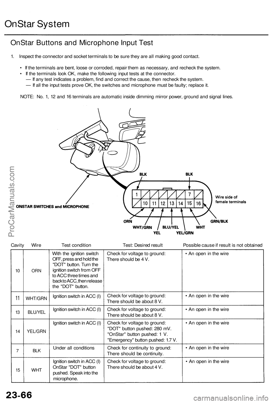
OnStar Syste m
OnSta r Button s an d Microphon e Inpu t Tes t
1. Inspec t th e connecto r an d socke t terminal s t o b e sur e the y ar e al l makin g goo d contact .
• I f th e terminal s ar e bent , loos e o r corroded , repai r the m a s necessary , an d rechec k th e system .
• I f th e terminal s loo k OK , mak e th e followin g inpu t test s a t th e connector .
— If an y tes t indicate s a problem , fin d an d correc t th e cause , the n rechec k th e system .
— If al l th e inpu t test s prov e OK , th e switche s an d microphon e mus t b e faulty ; replac e it .
NOTE : No . 1 , 1 2 an d 1 6 terminal s ar e automati c insid e dimmin g mirro r power , groun d an d signa l lines .
Cavit y Wir e Test conditio n Test: Desire d resul t Possible caus e if resul t i s no t obtaine d
10
1 1
13
1 4
7
15
OR N
WHT/GR N
BLU/YEL
YEL/GR N
BLK
WH T
With th e ignitio n switc h
OFF , pres s an d hol d th e
"DOT " button . Tur n th e
ignitio n switc h fro m OF F
t o AC C thre e time s an d
bac k to ACC , the n releas e
th e "DOT " button .
Ignitio n switc h in AC C (I )
Ignitio n switc h in AC C (I)
Ignitio n switc h in AC C (I )
Unde r al l condition s
Ignitio n switc h in AC C (I)
OnSta r "DOT " butto n
pushed . Spea k int o th e
microphone . Chec
k fo r voltag e to ground :
Ther e shoul d b e 4 V .
Chec k fo r voltag e to ground :
Ther e shoul d b e abou t 8 V .
Chec k fo r voltag e to ground :
Ther e shoul d b e abou t 8 V .
Chec k fo r voltag e to ground :
"DOT " butto n pushed : 28 0 mV .
"OnStar " butto n pushed : 1 V .
"Emergency " butto n pushed : 1. 7 V .
Chec k fo r continuit y t o ground :
Ther e shoul d b e continuity .
Chec k fo r voltag e to ground :
Ther e shoul d b e abou t 4 V . •
A n ope n in th e wir e
• A n ope n in th e wir e
• A n ope n in th e wir e
• A n ope n in th e wir e
• A n ope n in th e wir e
• A n ope n in th e wir e
ProCarManuals.com
Page 57 of 1954
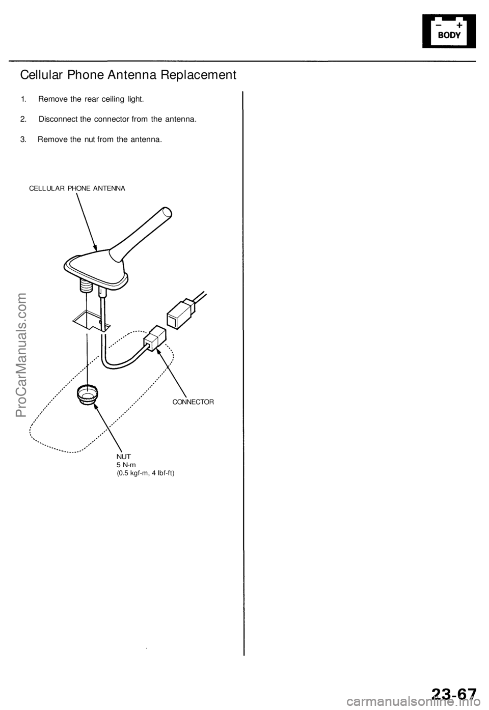
Cellular Phon e Antenn a Replacemen t
1. Remov e th e rea r ceilin g light .
2 . Disconnec t th e connecto r fro m th e antenna .
3 . Remov e th e nu t fro m th e antenna .
CELLULA R PHON E ANTENN A
CONNECTOR
NUT5 N- m(0.5 kgf-m , 4 Ibf-ft )
ProCarManuals.com
Page 58 of 1954
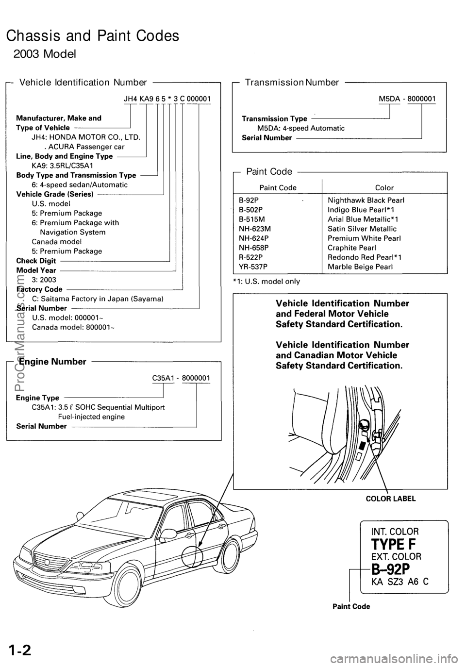
Chassis and Paint Codes
2003 Model
- Vehicle Identification Number
Transmission Number
Paint CodeProCarManuals.com
Page 59 of 1954

Emission Group Identification
(2003 model)
Under-hood Emissions Control Label
Engine and Evaporative FamiliesProCarManuals.com
Page 60 of 1954

Parts Marking
To deter vehicle theft, certain major components are marked with the vehicle identification number (VIN). Original
parts have self-adhesive labels. Replacement body parts have generic self-adhesive labels. The original engine or
transmission VIN plate is transferred to a replacement engine or transmission and attached with break-off bolts.
NOTE: Be careful not to damage the parts marking labels during body repair. Mask the labels before repairing the part.ProCarManuals.com