ACURA RL KA9 1996 Service Repair Manual
Manufacturer: ACURA, Model Year: 1996, Model line: RL KA9, Model: ACURA RL KA9 1996Pages: 1954, PDF Size: 61.44 MB
Page 551 of 1954
Troubleshooting
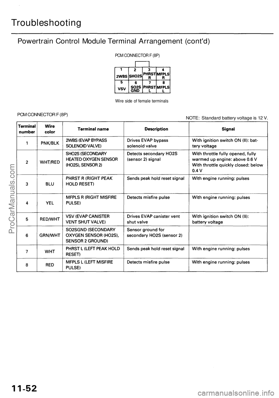
Powertrain Contro l Modul e Termina l Arrangemen t (cont'd )
PCM CONNECTO R F (8P )
Wir e sid e o f femal e terminal s
NOTE: Standar d batter y voltag e is 1 2 V .
PC
M CONNECTO R F (8P )
ProCarManuals.com
Page 552 of 1954
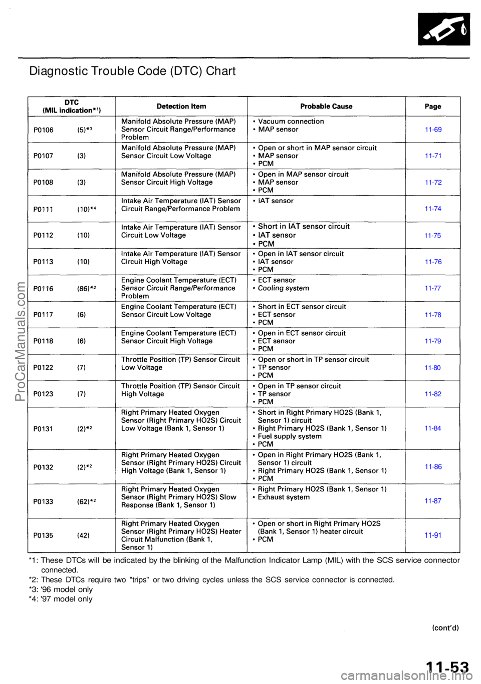
Diagnostic Troubl e Cod e (DTC ) Char t
*1: Thes e DTC s wil l b e indicate d b y th e blinkin g o f th e Malfunctio n Indicato r Lam p (MIL ) wit h th e SC S servic e connecto r
connected .
*2 : Thes e DTC s requir e tw o "trips " o r tw o drivin g cycle s unles s th e SC S servic e connecto r i s connected .
*3: '9 6 mode l onl y
*4: '9 7 mode l onl y
11-9 1
11-87
11-8 6
11-8 4
11-8
2
11-8
0
11-7
9
11-7
8
11-7
7
11-7
6
11-7
5
11-7
4
11-7 2
11-7 1
11-69
ProCarManuals.com
Page 553 of 1954
Troubleshooting
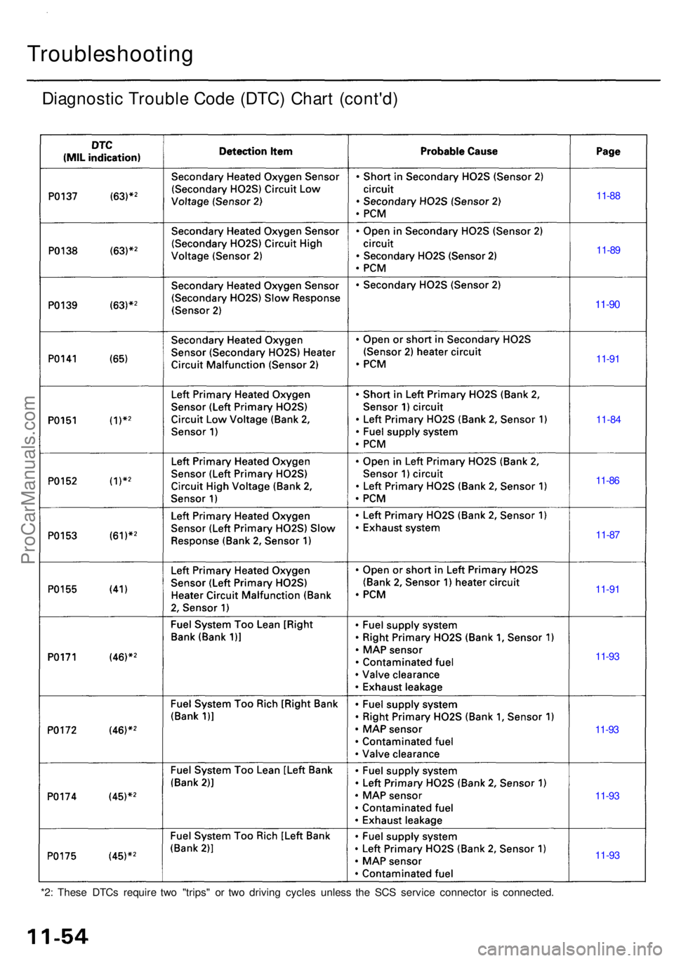
Diagnostic Troubl e Cod e (DTC ) Char t (cont'd )
11-88
11-8 9
11-90
11-91
11-8 4
11-8 6
11-8 7
11-9 1
11-9 3
11-9 3
11-9 3
11-9 3
*2: Thes e DTC s requir e tw o "trips " o r tw o drivin g cycle s unles s th e SC S servic e connecto r i s connected .
ProCarManuals.com
Page 554 of 1954
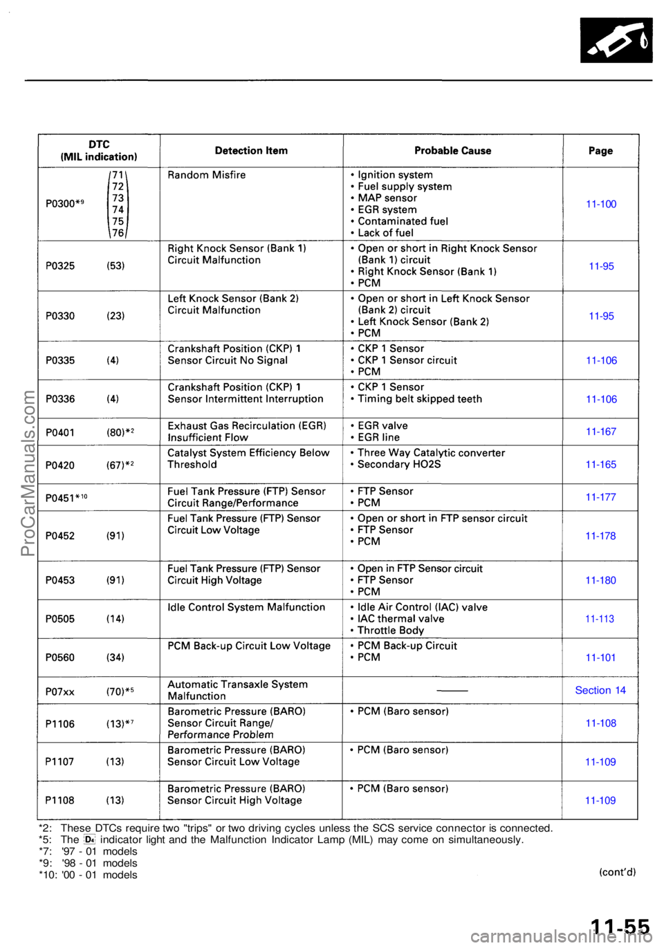
*2: Thes e DTC s requir e tw o "trips " o r tw o drivin g cycle s unles s th e SC S servic e connecto r i s connected .*5: Th e indicato r ligh t an d th e Malfunctio n Indicato r Lam p (MIL ) ma y com e o n simultaneously .
*7 : '9 7 - 0 1 model s
*9 : '9 8 - 0 1 model s
*10 : '0 0 - 0 1 model s
11-109
11-109
11-10 8
Sectio n 1 4
11-10 1
11-113
11-180
11-178
11-177
11-100
11-95
11-95
11-10 6
11-10 6
11-167
11-16 5
ProCarManuals.com
Page 555 of 1954
Troubleshooting
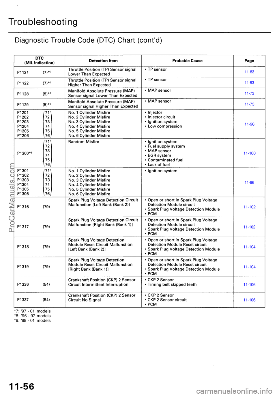
Diagnostic Troubl e Cod e (DTC ) Char t (cont'd )
11-83
11-8 3
11-7 3
11-7 3
11-96
11-10 0
11-96
11-10 2
11-10 2
11-104
11-10 4
11-106
11-10 6
*7: '9 7 - 0 1 model s
*8 : '9 6 - 9 7 model s
*9 : '9 8 - 0 1 model s
ProCarManuals.com
Page 556 of 1954
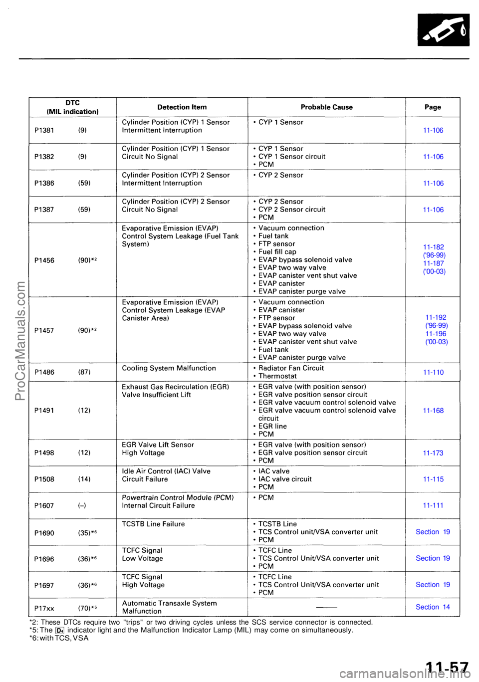
11-106
11-10 6
11-10 6
11-10 6
11-18 2
11-11 0
11-16 8
11-17 3
11-11 5
11-11 1
Sectio n 1 9
Sectio n 1 9
Sectio n 1 9
Sectio n 1 4
*2 : Thes e DTC s requir e tw o "trips " o r tw o drivin g cycle s unles s th e SC S servic e connecto r i s connected .
*5: Th e indicato r ligh t an d th e Malfunctio n Indicato r Lam p (MIL ) ma y com e o n simultaneously .*6: wit h TCS , VS A
11-18 7
('00-03) (' 96 -99 )
11-1 92
11-1 96
('00-03)
('96-99)
ProCarManuals.com
Page 557 of 1954
Troubleshooting
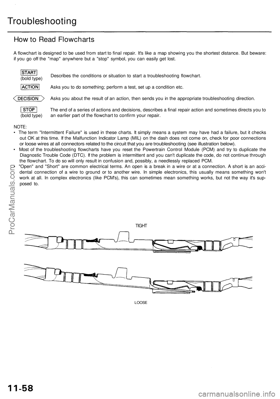
How to Read Flowcharts
A flowchart is designed to be used from start to final repair. It's like a map showing you the shortest distance. But beware:
if you go off the "map" anywhere but a "stop" symbol, you can easily get lost.
Describes the conditions or situation to start a troubleshooting flowchart.
Asks you to do something; perform a test, set up a condition etc.
Asks you about the result of an action, then sends you in the appropriate troubleshooting direction.
(bold type)
The end of a series of actions and decisions, describes a final repair action and sometimes directs you to
an earlier part of the flowchart to confirm your repair.
NOTE:
• The term "Intermittent Failure" is used in these charts. It simply means a system may have had a failure, but it checks
out OK at this time. If the Malfunction Indicator Lamp (MIL) on the dash does not come on, check for poor connections
or loose wires at all connectors related to the circuit that you are troubleshooting (see illustration below).
• Most of the troubleshooting flowcharts have you reset the Powertrain Control Module (PCM) and try to duplicate the
Diagnostic Trouble Code (DTC). If the problem is intermittent and you can't duplicate the code, do not continue through
the flowchart. To do so will only result in confusion and, possibly, a needlessly replaced PCM.
• "Open" and "Short" are common electrical terms. An open is a break in a wire or at a connection. A short is an acci-
dental connection of a wire to ground or to another wire. In simple electronics, this usually means something won't
work at all. In complex electronics (like PCM's), this can sometimes mean something works, but not the way it's sup-
posed to.
TIGHT
LOOSE
(bold type)ProCarManuals.com
Page 558 of 1954
PGM-FI Syste m
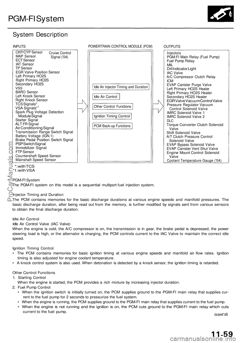
System Descriptio n
INPUTSPOWERTRAI N CONTRO L MODUL E (PCM )OUTPUT S
CKP/CYP Senso r
Cruise
Control
Signal ('04)MA P Senso rECT Senso rIAT Senso rTP Senso rEGR Valv e Positio n Senso rLeft Primar y HO2 SRight Primar y HO2 SSecondar y HO2 SVSSBAR O Senso rLeft Knoc k Senso rRight Knoc k Senso rTCS Signals *VSA Signals*1
Spar k Plu g Voltag e Detectio nModule Signa lStarte r Signa lALT F R Signa lAir Conditionin g Signa lTransmissio n Rang e Switc h Signa lBattery Voltag e (IGN.1 )Brake Peda l Positio n Switc h Signa lPSP Switc h Signa lImmobilize r Signa lFTP Senso rCountershaf t Spee d Senso rMainshaf t Spee d Senso r
Idle Ai r Injecto r Timin g an d Duratio n
Other Contro l Function s
Ignition Timin g Contro l
PCM Back-u p Function s
InjectorsPGM-FI Mai n Rela y (Fue l Pump )Fuel Pum p Rela yMILD4 Indicato r Ligh tIAC Valv eA/C Compresso r Clutc h Rela yICMEVA P Caniste r Purg e Valv eLeft Primar y HO2 S Heate rRight Primar y HO2 S Heate rSecondar y HO2 S Heate rEGR Valv e Vacuu m Contro l Valv ePressur e Regulato r Vacuu mControl Solenoi d Valv eIMRC Solenoi d Valv e 1IMR C Solenoi d Valv e 2DL CTorqu e Converte r Clutc h Solenoi dValveShift Solenoi d Valv eA/T Clutc h Pressur e Contro lSolenoid Valv eEVAP Bypas s Solenoi d Valv eEVAP Caniste r Ven t Shu t Valv eEngin e Moun t Contro l Solenoi dValve
PGM-F I Syste m
Th e PGM-F I syste m o n thi s mode l i s a sequentia l multipor t fue l injectio n system .
Injecto r Timin g an d Duratio n
Th e PC M contain s memorie s fo r th e basi c discharg e duration s a t variou s engin e speed s an d manifol d pressures . Th e
basi c discharg e duration , afte r bein g rea d ou t fro m th e memory , i s furthe r modifie d b y signal s sen t fro m variou s sensor s
t o obtai n th e fina l discharg e duration .
Idl e Ai r Contro l
Idl e Ai r Contro l Valv e (IA C Valve )
Whe n th e engin e i s cold , th e A/ C compresso r i s on , th e transmissio n i s i n gear , th e brak e peda l i s depressed , th e powe r
steerin g loa d i s high , o r th e alternato r i s charging , th e PC M control s curren t t o th e IA C Valv e t o maintai n th e correc t idl e
speed .
Ignition Timin g Contro l
• Th e PC M contain s memorie s fo r basi c ignitio n timin g a t variou s engin e speed s an d manifol d ai r flo w rates . Ignitio n
timin g i s als o adjuste d fo r engin e coolan t temperature .
• A knoc k contro l syste m is als o used . Whe n detonatio n i s detecte d b y a knoc k sensor , th e ignitio n timin g is retarded .
Othe r Contro l Function s
1 . Startin g Contro l
Whe n th e engin e is started , th e PC M provide s a ric h mixtur e b y increasin g injecto r duration .
2 . Fue l Pum p Contro l
• Whe n th e ignitio n switc h i s initiall y turne d on , th e PC M supplie s groun d t o th e PGM-F I mai n rela y tha t supplie s cur -
ren t t o th e fue l pum p fo r 2 second s t o pressuriz e th e fue l system .
• Whe n th e engin e is running , th e PC M supplie s groun d to th e PGM-F I mai n rela y tha t supplie s current to th e fue l pump .
• Whe n th e engin e is no t runnin g an d th e ignitio n i s on , th e PC M cut s groun d t o th e PGM-F I mai n rela y whic h cut s
curren t t o th e fue l pump .
*: wit h TC S*1: wit h VS A
Idle Ai r Contro l
Coolant Temperature Gauge ('04)
ProCarManuals.com
Page 559 of 1954
PGM-FI Syste m
System Descriptio n (cont'd )
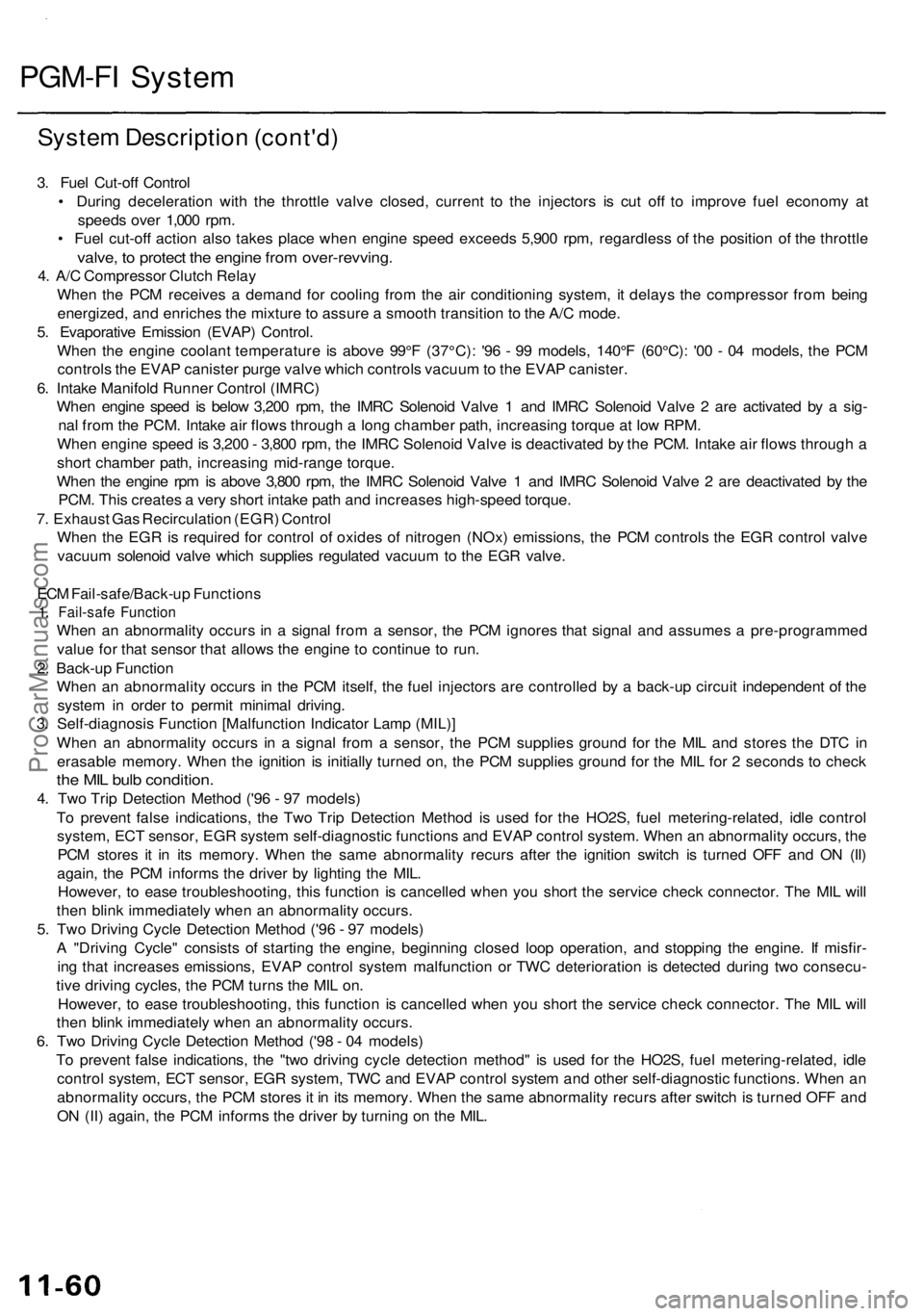
3. Fue l Cut-of f Contro l
• Durin g deceleratio n wit h th e throttl e valv e closed , curren t t o th e injector s i s cu t of f t o improv e fue l econom y a t
speed s ove r 1,00 0 rpm .
• Fue l cut-of f actio n als o take s plac e whe n engin e spee d exceed s 5,90 0 rpm , regardles s o f th e positio n o f th e throttl e
valve, t o protec t th e engin e fro m over-revving .
4. A/ C Compresso r Clutc h Rela y
Whe n th e PC M receive s a deman d fo r coolin g fro m th e ai r conditionin g system , i t delay s th e compresso r fro m bein g
energized , an d enriche s th e mixtur e to assur e a smoot h transitio n t o th e A/ C mode .
5 . Evaporativ e Emissio n (EVAP ) Control .
Whe n th e engin e coolan t temperatur e i s abov e 99° F (37°C) : '9 6 - 9 9 models , 140° F (60°C) : '0 0 - 0 4 models , th e PC M
control s th e EVA P caniste r purg e valv e whic h control s vacuu m to th e EVA P canister .
6 . Intak e Manifol d Runne r Contro l (IMRC )
Whe n engin e spee d i s belo w 3,20 0 rpm , th e IMR C Solenoi d Valv e 1 an d IMR C Solenoi d Valv e 2 ar e activate d b y a sig -
na l fro m th e PCM . Intak e ai r flow s throug h a lon g chambe r path , increasin g torqu e a t lo w RPM .
Whe n engin e spee d is 3,20 0 - 3,80 0 rpm , th e IMR C Solenoi d Valv e is deactivate d b y th e PCM . Intak e ai r flow s throug h a
shor t chambe r path , increasin g mid-rang e torque .
Whe n th e engin e rp m is abov e 3,80 0 rpm , th e IMR C Solenoi d Valv e 1 an d IMR C Solenoi d Valv e 2 ar e deactivate d b y th e
PCM . Thi s create s a ver y shor t intak e pat h an d increase s high-spee d torque .
7 . Exhaus t Ga s Recirculatio n (EGR ) Contro l
Whe n th e EG R is require d fo r contro l o f oxide s o f nitroge n (NOx ) emissions , th e PC M control s th e EG R contro l valv e
vacuu m solenoi d valv e whic h supplie s regulate d vacuu m to th e EG R valve .
EC M Fail-safe/Back-u p Function s
1. Fail-saf e Functio n
When a n abnormalit y occur s i n a signa l fro m a sensor , th e PC M ignore s tha t signa l an d assume s a pre-programme d
valu e fo r tha t senso r tha t allow s th e engine to continu e t o run .
2 . Back-u p Functio n
Whe n a n abnormalit y occur s i n th e PC M itself , th e fue l injector s ar e controlle d b y a back-u p circui t independen t o f th e
syste m in orde r t o permi t minima l driving .
3 . Self-diagnosi s Functio n [Malfunctio n Indicato r Lam p (MIL) ]
Whe n a n abnormalit y occur s i n a signa l fro m a sensor , th e PC M supplie s groun d fo r th e MI L an d store s th e DT C in
erasabl e memory . Whe n th e ignitio n i s initiall y turne d on , th e PC M supplie s groun d fo r th e MI L fo r 2 second s t o chec k
the MI L bul b condition .
4. Tw o Tri p Detectio n Metho d ('9 6 - 9 7 models )
T o preven t fals e indications , th e Tw o Tri p Detectio n Metho d i s use d fo r th e HO2S , fue l metering-related , idl e contro l
system , EC T sensor , EG R syste m self-diagnosti c function s an d EVA P contro l system . Whe n a n abnormalit y occurs , th e
PC M store s i t i n it s memory . Whe n th e sam e abnormalit y recur s afte r th e ignitio n switc h i s turne d OF F an d O N (II )
again , th e PC M inform s th e drive r b y lightin g th e MIL .
However , t o eas e troubleshooting , thi s functio n i s cancelle d whe n yo u shor t th e servic e chec k connector . Th e MI L wil l
the n blin k immediatel y whe n a n abnormalit y occurs .
5 . Tw o Drivin g Cycl e Detectio n Metho d ('9 6 - 9 7 models )
A "Drivin g Cycle " consist s o f startin g th e engine , beginnin g close d loo p operation , an d stoppin g th e engine . I f misfir -
in g tha t increase s emissions , EVA P contro l syste m malfunctio n o r TW C deterioratio n i s detecte d durin g tw o consecu -
tiv e drivin g cycles , th e PC M turn s th e MI L on .
However , t o eas e troubleshooting , thi s functio n i s cancelle d whe n yo u shor t th e servic e chec k connector . Th e MI L wil l
the n blin k immediatel y whe n a n abnormalit y occurs .
6 . Tw o Drivin g Cycl e Detectio n Metho d ('9 8 - 0 4 models )
T o preven t fals e indications , th e "tw o drivin g cycl e detectio n method " i s use d fo r th e HO2S , fue l metering-related , idl e
contro l system , EC T sensor , EG R system , TW C an d EVA P contro l syste m an d othe r self-diagnosti c functions . Whe n a n
abnormalit y occurs , th e PC M store s it i n it s memory . Whe n th e sam e abnormalit y recur s afte r switc h is turne d OF F an d
O N (II ) again , th e PC M inform s th e drive r b y turnin g o n th e MIL .
ProCarManuals.com
Page 560 of 1954
How to Set Readiness Codes
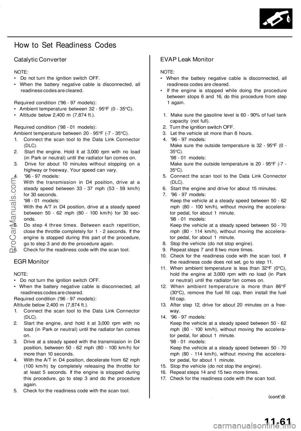
Catalytic Converter
NOTE:
• Do not turn the ignition switch OFF.
• When the battery negative cable is disconnected, all
readiness codes are cleared.
Required condition ('96 - 97 models):
• Ambient temperature between 32 - 95°F (0 - 35°C).
• Altitude below 2,400 m (7,874 ft.).
Required condition ('98 - 01 models):
Ambient temperature between 20 - 95°F (-7 - 35°C).
1. Connect the scan tool to the Data Link Connector
(DLC).
2. Start the engine. Hold it at 3,000 rpm with no load
(in Park or neutral) until the radiator fan comes on.
3. Drive for about 10 minutes without stopping on a
highway or freeway. Your speed can vary.
4. '96 - 97 models:
With the transmission in D4 position, drive at a
steady speed between 33 - 37 mph (53 - 59 km/h)
for 30 seconds.
'98 - 01 models:
With the A/T in D4 position, drive at a steady speed
between 50 - 62 mph (80 - 100 km/h) for 30 sec-
onds.
5. Do step 4 three times. Between each repetition,
close the throttle completely for 1 - 2 seconds. If the
engine is stopped during this part of the procedure,
go to step 3 and do the procedure again.
6. Check for the readiness code with the scan tool.
EGR Monitor
NOTE:
• Do not turn the ignition switch OFF.
• When the battery negative cable is disconnected, all
readiness codes are cleared.
Required condition ('96 - 97 models):
Altitude below 2,400 m (7,874 ft.).
1. Connect the scan tool to the Data Link Connector
(DLC).
2. Start the engine, and hold it at 3,000 rpm with no
load (in Park or neutral) until the radiator fan comes
on.
3. Drive at a steady speed with the transmission in D4
position, between 50 - 62 mph (80 - 100 km/h) for
more than 10 seconds.
4. With the A/T in D4 position, decelerate from 62 mph
(100 km/h) by completely releasing the throttle for
at least 5 seconds. If the engine is stopped during
this procedure, go to step 3 and do the procedure
again.
5. Check for the readiness code with the scan tool.
EVAP Leak Monitor
NOTE:
• When the battery negative cable is disconnected, all
readiness codes are cleared.
• If the engine is stopped while doing the procedure
between stops 6 and 16, do this procedure from step
1 again.
1. Make sure the gasoline level is 60 - 90% of fuel tank
capacity (not full).
2. Turn the ignition switch OFF.
3. Let the vehicle sit more than 8 hours.
4. '96 - 97 models:
Make sure the outside temperature is 32 - 95°F (0 -
35°C).
'98 - 01 models:
Make sure the outside temperature is 20 - 95°F (-7 -
35°C).
5. Connect the scan tool to the Data Link Connector
(DLC).
6. Start the engine and drive for about 15 minutes.
7. '96 - 97 models:
Keep the vehicle at a steady speed between 50 - 62
mph (80 - 100 km/h), without moving the accelera-
tor pedal, for about 1 minute.
'98 - 01 models:
Keep the vehicle at a steady speed between 50 - 70
mph (80 - 114 km/h), without moving the accelera-
tor pedal, for about 1 minute.
8. Stop the vehicle (do not stop engine).
9. Repeat steps 7 and 8 two more times.
10. Check for the readiness code with the scan tool. If
the readiness code does not set, go to step 11.
11. When ambient temperature is less than 32°F (0°C),
hold the engine at 3,000 rpm with no load (in Park
or neutral) until the radiator fan comes on.
12. When ambient temperature is more than 86°F
(30°C), remove the fuel fill cap, then install the fuel
fill cap.
13. After step 12, drive for about 20 minutes on a free-
way.
14. '96 - 97 models:
Keep the vehicle at a steady speed between 50 - 62
mph (80 - 100 km/h), without moving the accelera-
tor pedal, for about 1 minute.
'98 - 01 models:
Keep the vehicle at a steady speed between 50 - 70
mph (80 - 114 km/h), without moving the accelera-
tor pedal, for about 1 minute.
15. Stop the vehicle (do not stop the engine).
16. Repeat steps 14 and 15 two more times.
17. Check for the readiness code with the scan tool.ProCarManuals.com