ACURA RL KA9 1996 Service Repair Manual
Manufacturer: ACURA, Model Year: 1996, Model line: RL KA9, Model: ACURA RL KA9 1996Pages: 1954, PDF Size: 61.44 MB
Page 721 of 1954
Description
Power Flo w (cont'd )
Position
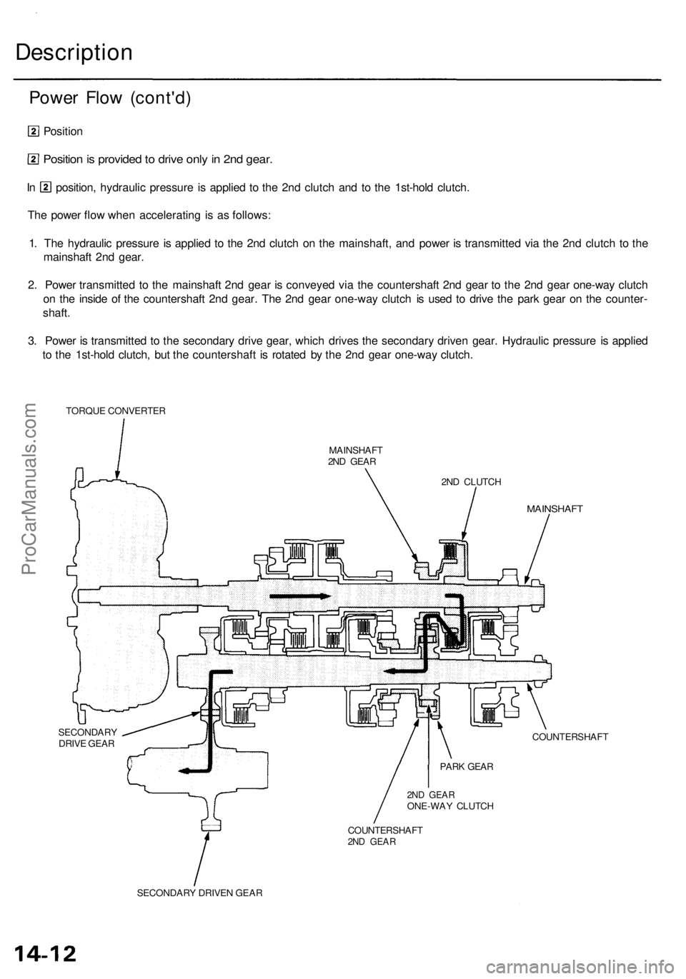
Position is provide d to driv e onl y in 2n d gear .
In position , hydrauli c pressur e i s applie d t o th e 2n d clutc h an d t o th e 1st-hol d clutch .
Th e powe r flo w whe n acceleratin g i s a s follows :
1 . Th e hydrauli c pressur e is applie d t o th e 2n d clutc h o n th e mainshaft , an d powe r i s transmitte d vi a th e 2n d clutc h t o th e
mainshaf t 2n d gear .
2 . Powe r transmitte d t o th e mainshaf t 2n d gea r i s conveye d vi a th e countershaf t 2n d gea r t o th e 2n d gea r one-wa y clutc h
o n th e insid e o f th e countershaf t 2n d gear . Th e 2n d gea r one-wa y clutc h i s use d t o driv e th e par k gea r o n th e counter -
shaft .
3 . Powe r i s transmitte d t o th e secondar y driv e gear , whic h drive s th e secondar y drive n gear . Hydrauli c pressur e i s applie d
t o th e 1st-hol d clutch , bu t th e countershaf t i s rotate d b y th e 2n d gea r one-wa y clutch .
TORQU E CONVERTE R
MAINSHAFT
2N D GEA R
2ND CLUTC H
MAINSHAF T
SECONDAR YDRIVE GEA R COUNTERSHAF
T
2ND GEA RONE-WA Y CLUTC H
COUNTERSHAF T
2ND GEA R
SECONDAR Y DRIVE N GEA R PAR
K GEA R
ProCarManuals.com
Page 722 of 1954
Position
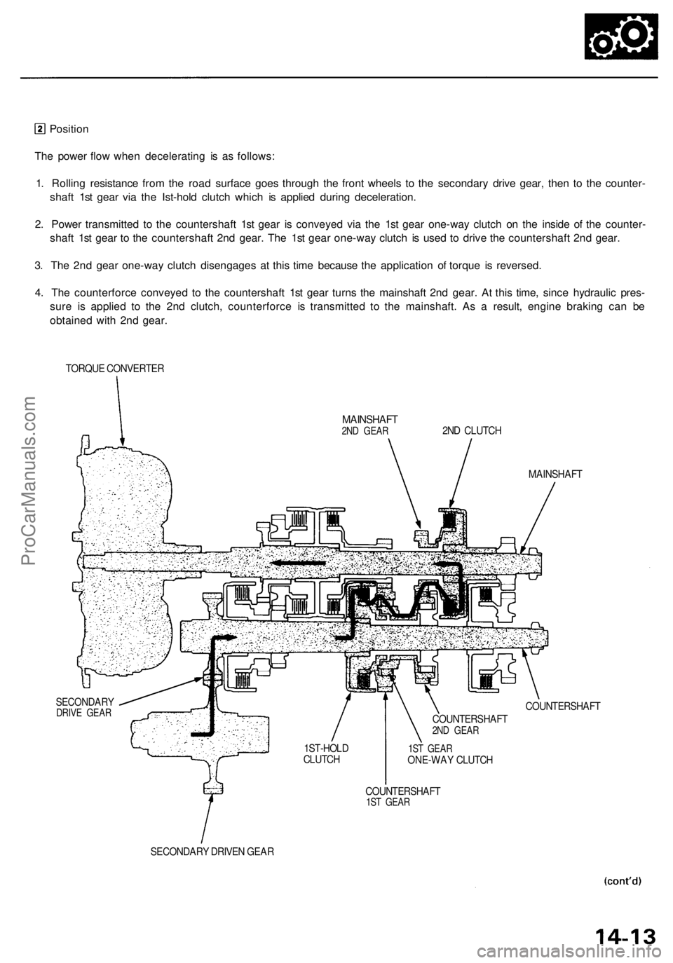
The power flow when decelerating is as follows:
1. Rolling resistance from the road surface goes through the front wheels to the secondary drive gear, then to the counter-
shaft 1st gear via the Ist-hold clutch which is applied during deceleration.
2. Power transmitted to the countershaft 1st gear is conveyed via the 1st gear one-way clutch on the inside of the counter-
shaft 1st gear to the countershaft 2nd gear. The 1st gear one-way clutch is used to drive the countershaft 2nd gear.
3. The 2nd gear one-way clutch disengages at this time because the application of torque is reversed.
4. The counterforce conveyed to the countershaft 1st gear turns the mainshaft 2nd gear. At this time, since hydraulic pres-
sure is applied to the 2nd clutch, counterforce is transmitted to the mainshaft. As a result, engine braking can be
obtained with 2nd gear.
TORQUE CONVERTER
MAINSHAFT
2ND GEAR
2ND CLUTCH
MAINSHAFT
SECONDARY
DRIVE GEAR
COUNTERSHAFT
1ST GEAR
ONE-WAY CLUTCH
COUNTERSHAFT
1ST GEAR
SECONDARY DRIVEN GEAR
1ST-HOLD
CLUTCH
COUNTERSHAFT
2ND GEARProCarManuals.com
Page 723 of 1954
Description
Power Flo w (cont'd )
In o r position , th e optimu m gea r i s automaticall y selecte d fro m 1st , 2nd , 3rd , an d 4t h gears , accordin g t o condition s
suc h a s th e balanc e betwee n throttl e openin g (engin e load ) an d vehicl e speed .
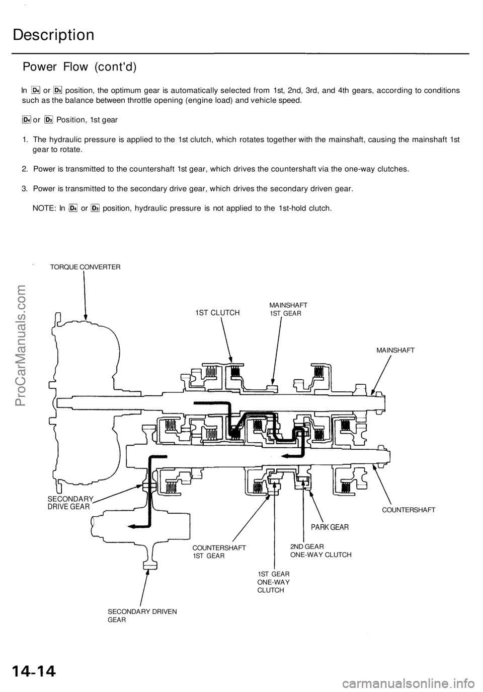
or Position , 1s t gea r
1 . Th e hydrauli c pressur e i s applie d t o th e 1s t clutch , whic h rotate s togethe r wit h th e mainshaft , causin g th e mainshaf t 1s t
gea r t o rotate .
2 . Powe r i s transmitte d t o th e countershaf t 1s t gear , whic h drive s th e countershaf t vi a th e one-wa y clutches .
3 . Powe r i s transmitte d t o th e secondar y driv e gear , whic h drive s th e secondar y drive n gear .
NOTE : I n o r position , hydrauli c pressur e i s no t applie d t o th e 1st-hol d clutch .
TORQU E CONVERTE R
MAINSHAFT
1ST GEA R
2ND GEA R
ONE-WA Y CLUTC H
1ST GEA RONE-WA Y
CLUTC H MAINSHAF
T
COUNTERSHAF T
SECONDAR Y DRIVE N
GEAR
COUNTERSHAF T1ST GEA R
PARK GEAR
SECONDARYDRIVE GEAR
1ST CLUTCH
ProCarManuals.com
Page 724 of 1954
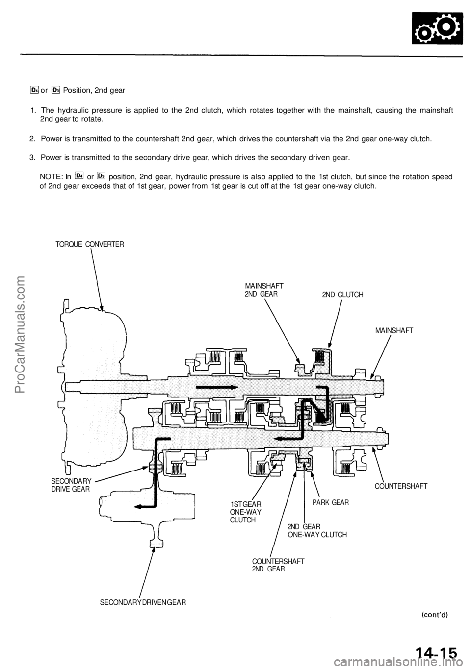
or Position, 2nd gear
1. The hydraulic pressure is applied to the 2nd clutch, which rotates together with the mainshaft, causing the mainshaft
2nd gear to rotate.
2. Power is transmitted to the countershaft 2nd gear, which drives the countershaft via the 2nd gear one-way clutch.
3. Power is transmitted to the secondary drive gear, which drives the secondary driven gear.
NOTE: In or position, 2nd gear, hydraulic pressure is also applied to the 1st clutch, but since the rotation speed
of 2nd gear exceeds that of 1st gear, power from 1st gear is cut off at the 1st gear one-way clutch.
TORQUE CONVERTER
SECONDARY
DRIVE GEAR
MAINSHAFT
2ND GEAR
2ND CLUTCH
MAINSHAFT
COUNTERSHAFT
2ND GEAR
ONE-WAY CLUTCH
COUNTERSHAFT
2ND GEAR
SECONDARY DRIVEN GEAR
1ST GEAR
ONE-WAY
CLUTCH
PARK GEARProCarManuals.com
Page 725 of 1954
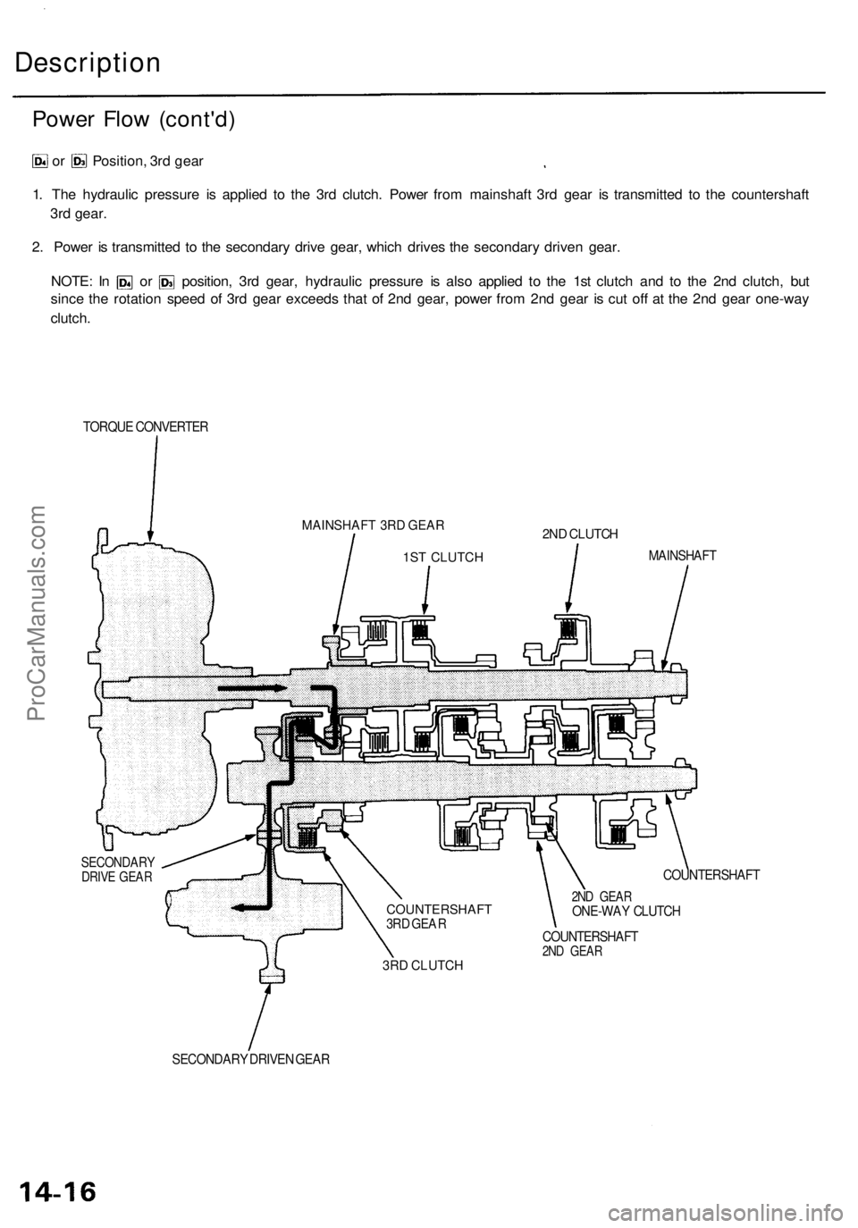
Power Flo w (cont'd )
or Position , 3r d gea r
1 . Th e hydrauli c pressur e i s applie d t o th e 3r d clutch . Powe r fro m mainshaf t 3r d gea r i s transmitte d t o th e countershaf t
3r d gear .
2 . Powe r i s transmitte d t o th e secondar y driv e gear , whic h drive s th e secondar y drive n gear .
NOTE : I n o r position , 3r d gear , hydrauli c pressur e i s als o applie d t o th e 1s t clutc h an d t o th e 2n d clutch , bu t
sinc e th e rotatio n spee d o f 3r d gea r exceed s tha t o f 2n d gear , powe r fro m 2n d gea r i s cu t of f a t th e 2n d gea r one-wa y
clutch .
TORQU E CONVERTE R
SECONDAR YDRIVE GEA RCOUNTERSHAF T
2ND GEA RONE-WA Y CLUTC H
COUNTERSHAF T
2ND GEA R
SECONDAR Y DRIVE N GEA R
3RD CLUTCH
COUNTERSHAFT3RD GEA R MAINSHAFT
2ND CLUTCH
1ST
CLUTCH
MAINSHAFT 3RD GEAR
Description
ProCarManuals.com
Page 726 of 1954
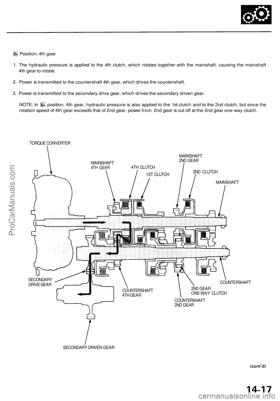
Position, 4th gear
1. The hydraulic pressure is applied to the 4th clutch, which rotates together with the mainshaft, causing the mainshaft
4th gear to rotate.
2. Power is transmitted to the countershaft 4th gear, which drives the countershaft.
3. Power is transmitted to the secondary drive gear, which drives the secondary driven gear.
NOTE: In position, 4th gear, hydraulic pressure is also applied to the 1st clutch and to the 2nd clutch, but since the
rotation speed of 4th gear exceeds that of 2nd gear, power from 2nd gear is cut off at the 2nd gear one-way clutch.
TORQUE CONVERTER
MAINSHAFT
4TH GEAR
MAINSHAFT
2ND GEAR
SECONDARY
DRIVE GEAR
COUNTERSHAFT
2ND GEAR
SECONDARY DRIVEN GEAR
COUNTERSHAFT
4TH GEAR
2ND GEAR
ONE-WAY CLUTCH
COUNTERSHAFT
MAINSHAFT
2ND CLUTCH
4TH CLUTCH
1ST CLUTCHProCarManuals.com
Page 727 of 1954
Description
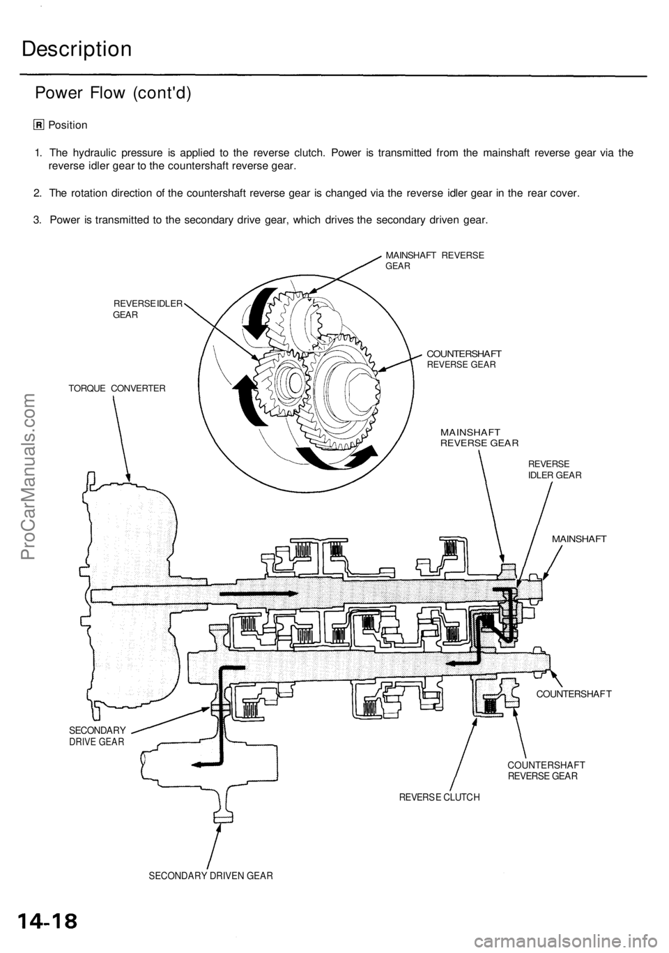
Power Flo w (cont'd )
Position
1 . Th e hydrauli c pressur e i s applie d t o th e revers e clutch . Powe r i s transmitte d fro m th e mainshaf t revers e gea r vi a th e
revers e idle r gea r t o th e countershaf t revers e gear .
2 . Th e rotatio n directio n o f th e countershaf t revers e gea r i s change d vi a th e revers e idle r gea r i n th e rea r cover .
3 . Powe r i s transmitte d t o th e secondar y driv e gear , whic h drive s th e secondar y drive n gear .
REVERS E IDLE R
GEA R MAINSHAF
T REVERS E
GEAR
COUNTERSHAF TREVERSE GEA R
TORQU E CONVERTE R
REVERSEIDLER GEA R
MAINSHAF T
COUNTERSHAF T
SECONDARYDRIVE GEAR
COUNTERSHAFTREVERSE GEAR
REVERS E CLUTC H
SECONDARY DRIVEN GEAR
MAINSHAF T
REVERSE GEAR
ProCarManuals.com
Page 728 of 1954
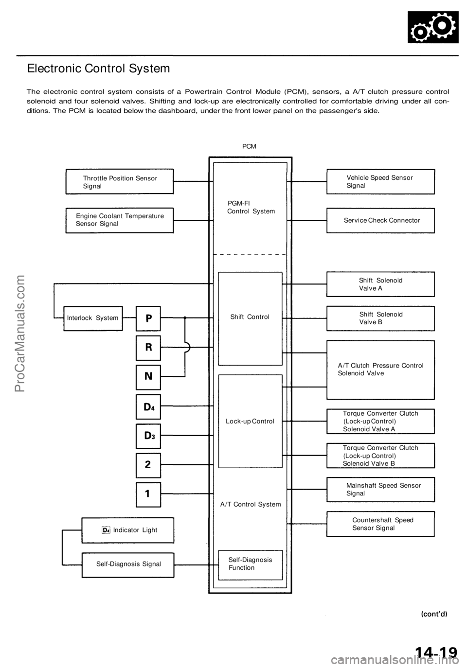
Electronic Control System
The electronic control system consists of a Powertrain Control Module (PCM), sensors, a A/T clutch pressure control
solenoid and four solenoid valves. Shifting and lock-up are electronically controlled for comfortable driving under all con-
ditions. The PCM is located below the dashboard, under the front lower panel on the passenger's side.
PCM
Throttle Position Sensor
Signal
Engine Coolant Temperature
Sensor Signal
Indicator Light
Self-Diagnosis Signal
PGM-FI
Control System
Shift Control
Lock-up Control
A/T Control System
Self-Diagnosis
Function
Vehicle Speed Sensor
Signal
Service Check Connector
Shift Solenoid
Valve A
Shift Solenoid
Valve B
A/T Clutch Pressure Control
Solenoid Valve
Torque Converter Clutch
(Lock-up Control)
Solenoid Valve A
Torque Converter Clutch
(Lock-up Control)
Solenoid Valve B
Mainshaft Speed Sensor
Signal
Countershaft Speed
Sensor Signal
Interlock SystemProCarManuals.com
Page 729 of 1954
Description
Electronic Contro l Syste m (cont'd )
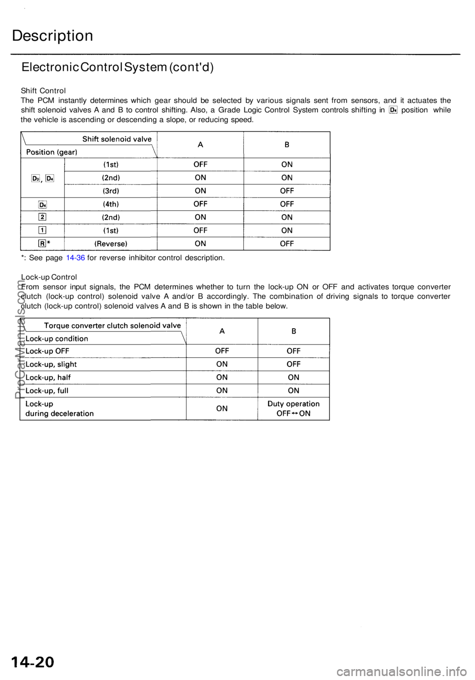
Shift Contro l
Th e PC M instantl y determine s whic h gea r shoul d b e selecte d b y variou s signal s sen t fro m sensors , an d i t actuate s th e
shif t solenoi d valve s A an d B to contro l shifting . Also , a Grad e Logi c Contro l Syste m control s shiftin g i n positio n whil e
th e vehicl e is ascendin g o r descendin g a slope , o r reducin g speed .
* : Se e pag e 14-3 6 fo r revers e inhibito r contro l description .
Lock-u p Contro l
Fro m senso r inpu t signals , th e PC M determine s whethe r t o tur n th e lock-u p O N o r OF F an d activate s torqu e converte r
clutc h (lock-u p control ) solenoi d valv e A and/o r B accordingly . Th e combinatio n o f drivin g signal s t o torqu e converte r
clutc h (lock-u p control ) solenoi d valve s A an d B is show n in th e tabl e below .
ProCarManuals.com
Page 730 of 1954

Grade Logic Control System
How it works:
The PCM compares actual driving conditions with driving conditions memorized in the PCM, based on the input from the
vehicle speed sensor, throttle position sensor, engine coolant temperature sensor, barometric pressure sensor, brake
pedal position switch signal and shift lever position signal, to control shifting while a vehicle is ascending or descending a
slope.ProCarManuals.com