ACURA RL KA9 1996 Service Repair Manual
Manufacturer: ACURA, Model Year: 1996, Model line: RL KA9, Model: ACURA RL KA9 1996Pages: 1954, PDF Size: 61.44 MB
Page 761 of 1954
Troubleshooting Procedure s
(cont'd)
SRS component s ar e locate d i n thi s area . Revie w th e SR S componen t locations , precautions , an d procedure s i n th e SR S
( sectio n 24 ) befor e performin g repair s o r service .
1. Remov e th e righ t doo r sil l moldin g (se e sectio n 20 ).
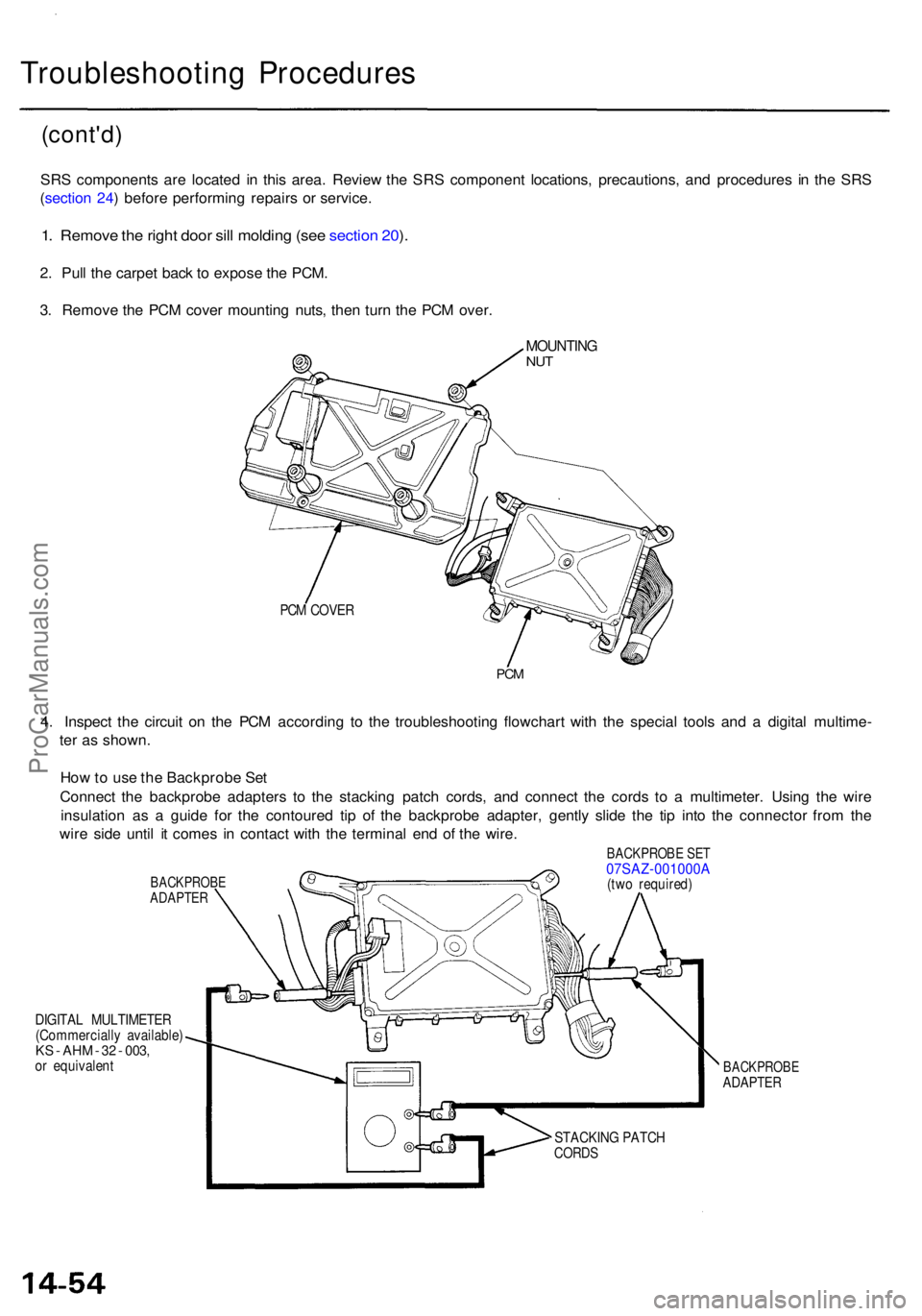
2 . Pul l th e carpe t bac k t o expos e th e PCM .
3 . Remov e th e PC M cove r mountin g nuts , the n tur n th e PC M over .
PCM COVE R
PCM
4. Inspec t th e circui t o n th e PC M accordin g t o th e troubleshootin g flowchar t wit h th e specia l tool s an d a digita l multime -
te r a s shown .
Ho w to us e th e Backprob e Se t
Connec t th e backprob e adapter s t o th e stackin g patc h cords , an d connec t th e cord s t o a multimeter . Usin g th e wir e
insulatio n a s a guid e fo r th e contoure d ti p o f th e backprob e adapter , gentl y slid e th e ti p int o th e connecto r fro m th e
wir e sid e unti l i t come s i n contac t wit h th e termina l en d o f th e wire .
BACKPROB EADAPTER
DIGITAL MULTIMETE R
(Commerciall y available )
KS - AH M - 3 2 - 003 ,or equivalen t
BACKPROB E SE T07SAZ-001000 A(two required )
BACKPROB EADAPTER
STACKIN G PATC HCORDS
MOUNTIN GNUT
ProCarManuals.com
Page 762 of 1954
PCM Rese t Procedur e
1 . Mak e sur e yo u hav e th e anti-thef t cod e fo r th e radio , the n writ e dow n th e frequencie s fo r th e radio' s prese t buttons .
2 . Tur n th e ignitio n switc h OFF .
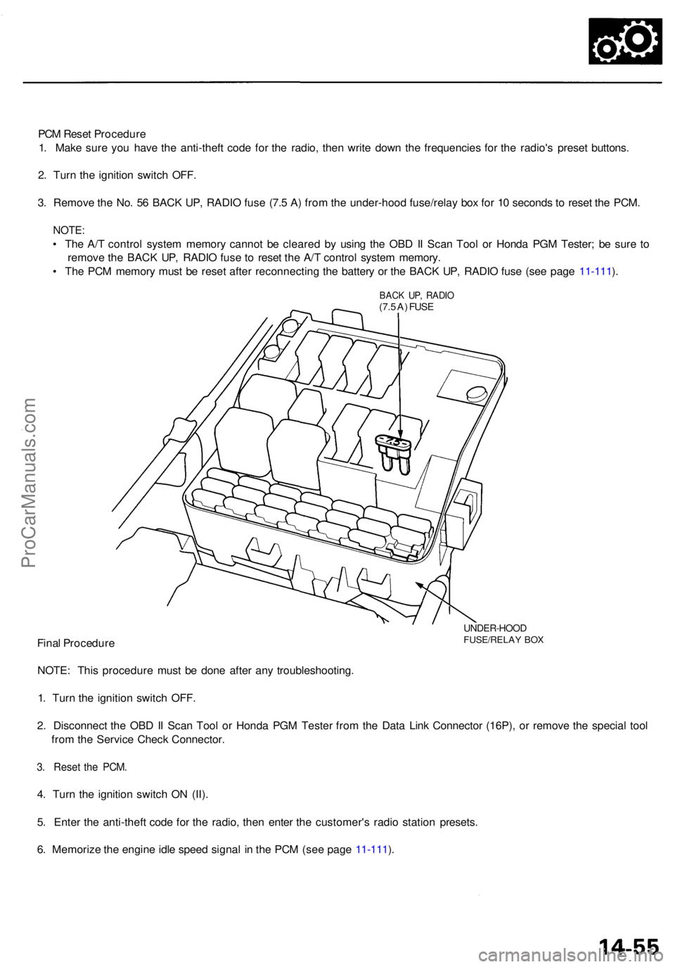
3 . Remov e th e No . 5 6 BAC K UP , RADI O fus e (7. 5 A ) fro m th e under-hoo d fuse/rela y bo x fo r 1 0 second s t o rese t th e PCM .
NOTE :
• Th e A/ T contro l syste m memor y canno t b e cleare d b y usin g th e OB D II Sca n Too l o r Hond a PG M Tester ; b e sur e t o
remov e th e BAC K UP , RADI O fus e t o rese t th e A/ T contro l syste m memory .
• Th e PC M memor y mus t b e rese t afte r reconnectin g th e batter y o r th e BAC K UP , RADI O fus e (se e pag e 11-111 ).
BAC K UP , RADI O(7.5 A ) FUS E
UNDER-HOO DFUSE/RELAY BO XFina l Procedur e
NOTE : Thi s procedur e mus t b e don e afte r an y troubleshooting .
1 . Tur n th e ignitio n switc h OFF .
2 . Disconnec t th e OB D II Sca n Too l o r Hond a PG M Teste r fro m th e Dat a Lin k Connecto r (16P) , o r remov e th e specia l too l
fro m th e Servic e Chec k Connector .
3. Rese t th e PCM .
4. Tur n th e ignitio n switc h O N (II) .
5 . Ente r th e anti-thef t cod e fo r th e radio , the n ente r th e customer' s radi o statio n presets .
6 . Memoriz e th e engin e idl e spee d signa l i n th e PC M (se e pag e 11-111 ).
ProCarManuals.com
Page 763 of 1954
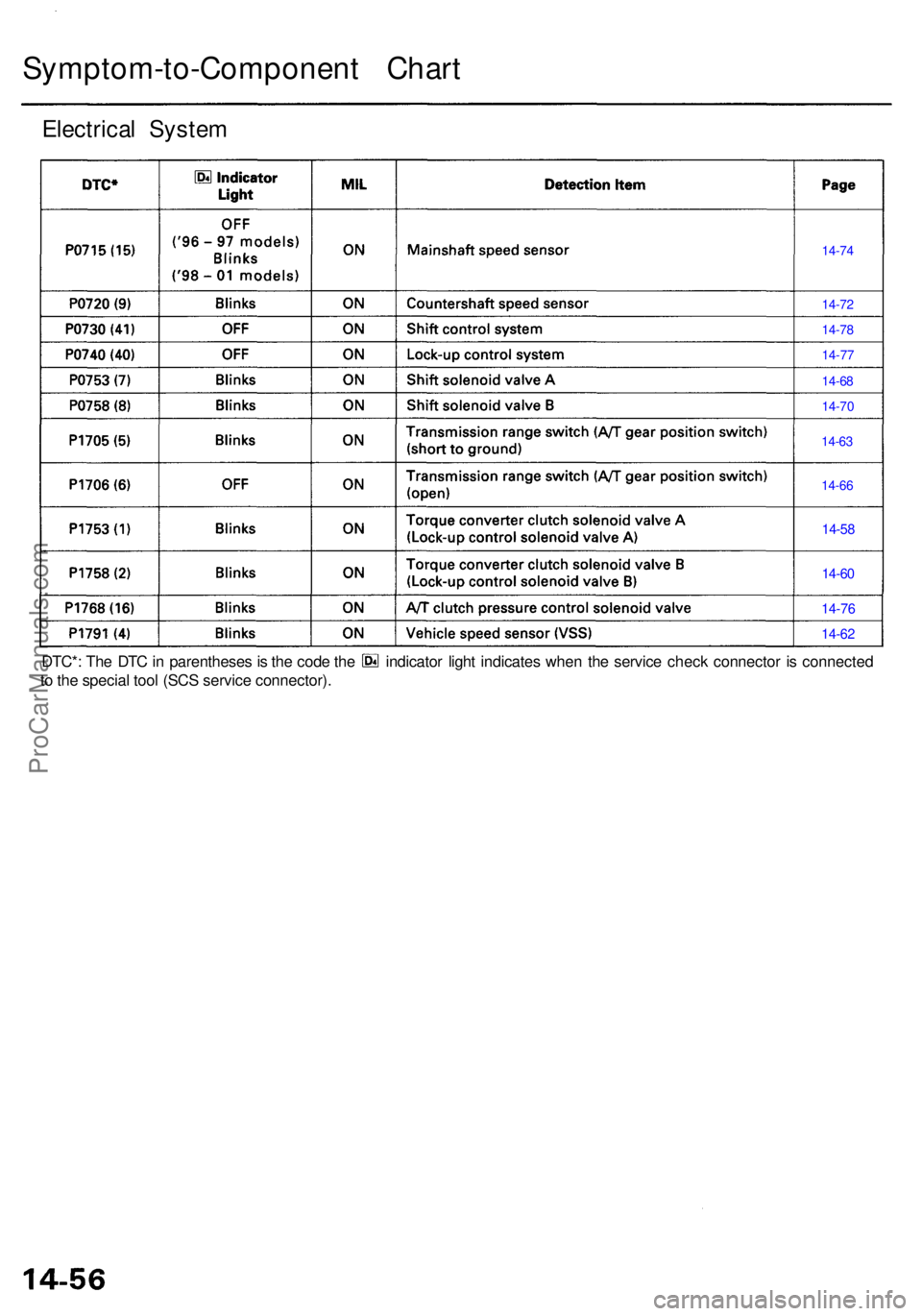
Symptom-to-Component Char t
Electrica l Syste m
14-74
14-7 2
14-7 8
14-7 7
14-68
14-7 0
14-6 3
14-6 6
14-58
14-6 0
14-7 6
14-6 2
DTC* : Th e DT C in parenthese s is th e cod e th e indicato r ligh t indicate s whe n th e servic e chec k connecto r i s connecte d
t o th e specia l too l (SC S servic e connector) .
ProCarManuals.com
Page 764 of 1954
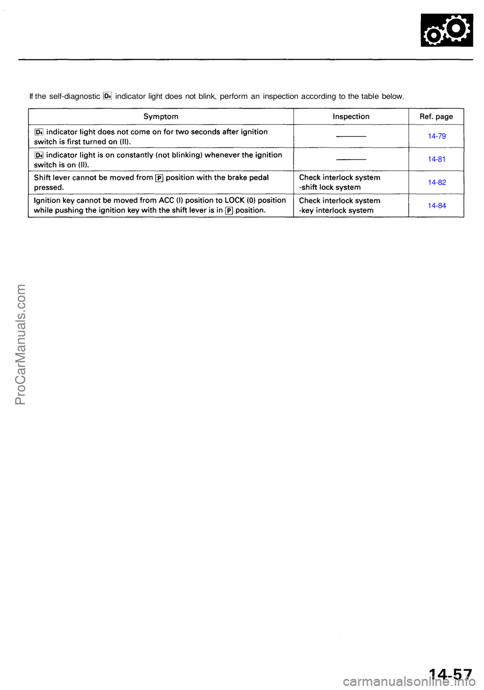
If th e self-diagnosti c indicato r ligh t doe s no t blink , perfor m a n inspectio n accordin g t o th e tabl e below .
14-79
14-8 1
14-82
14-84
ProCarManuals.com
Page 765 of 1954
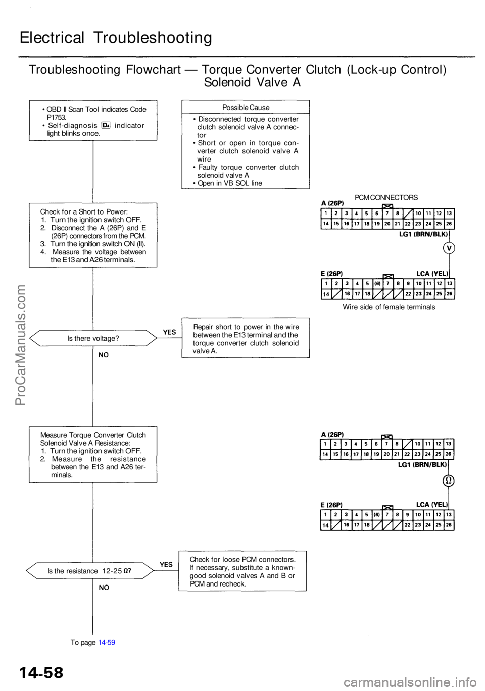
Electrical Troubleshootin g
Troubleshooting Flowchar t — Torqu e Converte r Clutc h (Lock-u p Control )
Solenoi d Valv e A
• OB D II Sca n Too l indicate s Cod eP1753 .• Self-diagnosi s indicato rlight blink s once .
Chec k fo r a Shor t t o Power :1. Tur n th e ignitio n switc h OFF .2. Disconnec t th e A (26P ) an d E
(26P ) connector s fro m th e PCM .
3. Tur n th e ignitio n switc h O N (II) .4. Measur e th e voltag e betwee nthe E1 3 an d A2 6 terminals .
Is ther e voltage ?
Measur e Torqu e Converte r Clutc h
Solenoi d Valv e A Resistance :
1. Tur n th e ignitio n switc h OFF .2. Measur e th e resistanc e
betwee n th e E1 3 an d A2 6 ter -
minals .
Is th e resistanc e 12-2 5
T o pag e 14-5 9 Possibl
e Caus e
• Disconnecte d torqu e converte r
clutc h solenoi d valv e A connec -
tor• Shor t o r ope n i n torqu e con -
verte r clutc h solenoi d valv e A
wir e
• Fault y torqu e converte r clutc h
solenoi d valv e A
• Ope n in V B SO L lin e
Repai r shor t t o powe r i n th e wir e
betwee n th e E1 3 termina l an d th etorqu e converte r clutc h solenoi d
valv e A .
Chec k fo r loos e PC M connectors .
I f necessary , substitut e a known -
goo d solenoi d valve s A an d B or
PC M an d recheck . PC
M CONNECTOR S
Wir e sid e o f femal e terminal s
ProCarManuals.com
Page 766 of 1954
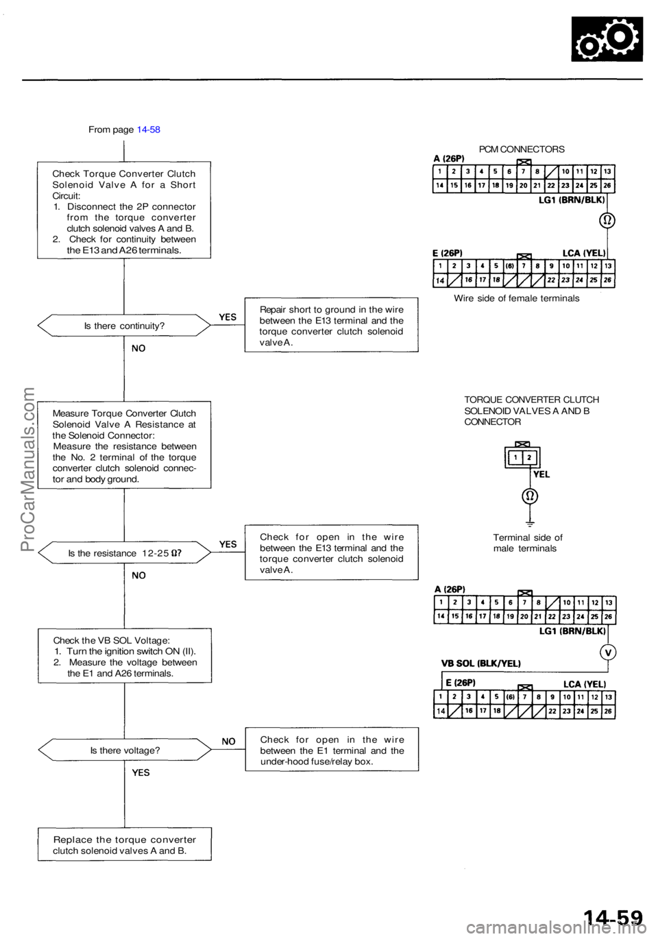
From pag e 14-5 8
Chec k Torqu e Converte r Clutc h
Solenoi d Valv e A fo r a Shor t
Circuit :
1 . Disconnec t th e 2 P connecto r
fro m th e torqu e converte r
clutc h solenoi d valve s A an d B .
2 . Chec k fo r continuit y betwee n
the E1 3 an d A2 6 terminals .
Is ther e continuity ?
Measur e Torqu e Converte r Clutc h
Solenoi d Valv e A Resistanc e a t
th e Solenoi d Connector :
Measur e th e resistanc e betwee n
th e No . 2 termina l o f th e torqu e
converte r clutc h solenoi d connec -
tor an d bod y ground .
Is th e resistanc e 12-2 5
Chec k th e V B SO L Voltage :
1. Tur n th e ignitio n switc h O N (II) .2. Measur e th e voltag e betwee n
th e E 1 an d A2 6 terminals .
I s ther e voltage ?
Replace th e torqu e converte rclutch solenoi d valve s A an d B . Repai
r shor t t o groun d in th e wir e
betwee n th e E1 3 termina l an d th e
torqu e converte r clutc h solenoi d
valv e A .
Chec k fo r ope n i n th e wir e
betwee n th e E1 3 termina l an d th e
torqu e converte r clutc h solenoi d
valv e A .
Chec k fo r ope n i n th e wir e
betwee n th e E 1 termina l an d th e
under-hoo d fuse/rela y box .
PCM CONNECTOR S
Wire sid e o f femal e terminal s
Termina l sid e o f
mal e terminal s
TORQUE CONVERTE R CLUTC HSOLENOI D VALVE S A AN D BCONNECTO R
ProCarManuals.com
Page 767 of 1954
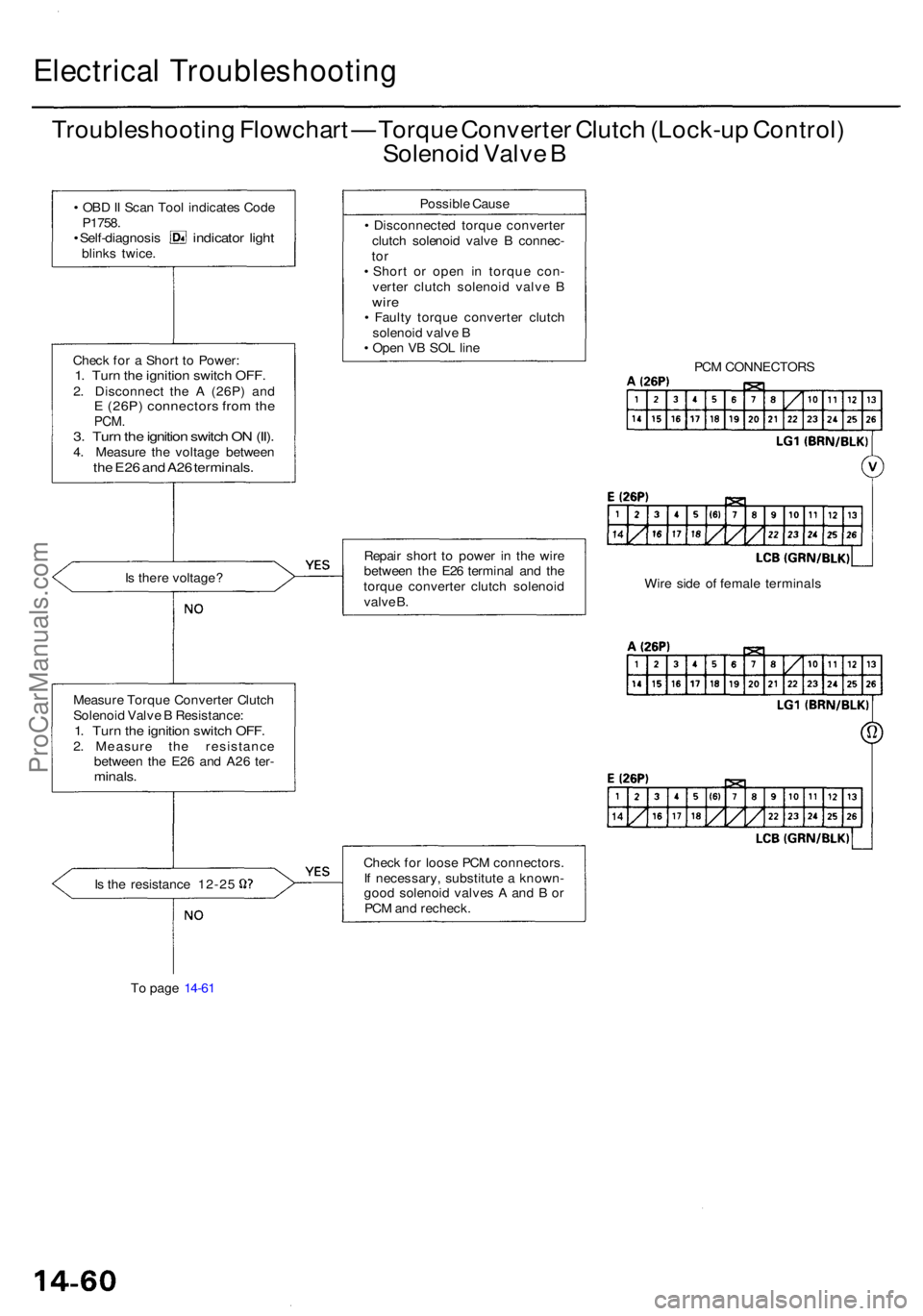
Electrical Troubleshootin g
Troubleshooting Flowchar t — Torqu e Converte r Clutc h (Lock-u p Control )
Solenoi d Valv e B
• OB D II Sca n Too l indicate s Cod e
P1758 .
• Self-diagnosi s indicator ligh tblink s twice .
Chec k fo r a Shor t t o Power :
1. Tur n th e ignitio n switc h OFF .2. Disconnec t th e A (26P ) an dE (26P ) connector s fro m th ePCM .3. Tur n th e ignitio n switc h O N (II) .4. Measur e th e voltag e betwee nthe E2 6 an d A2 6 terminals .
Is ther e voltage ?
Measur e Torqu e Converte r Clutc h
Solenoi d Valv e B Resistance :
1. Tur n th e ignitio n switc h OFF .2. Measur e th e resistanc e
betwee n th e E2 6 an d A2 6 ter -
minals .
Is th e resistanc e 12-2 5
T o pag e 14-6 1 Possibl
e Caus e
• Disconnecte d torqu e converte r
clutc h solenoi d valv e B connec -
tor• Shor t o r ope n i n torqu e con -
verte r clutc h solenoi d valv e B
wir e• Fault y torqu e converte r clutc h
solenoi d valv e B
• Ope n V B SO L lin e
Repai r shor t t o powe r i n th e wir e
betwee n th e E2 6 termina l an d th e
torqu e converte r clutc h solenoi d
valv e B .
Chec k fo r loos e PC M connectors .
I f necessary , substitut e a known -
goo d solenoi d valve s A an d B or
PC M an d recheck . PC
M CONNECTOR S
Wir e sid e o f femal e terminal s
ProCarManuals.com
Page 768 of 1954
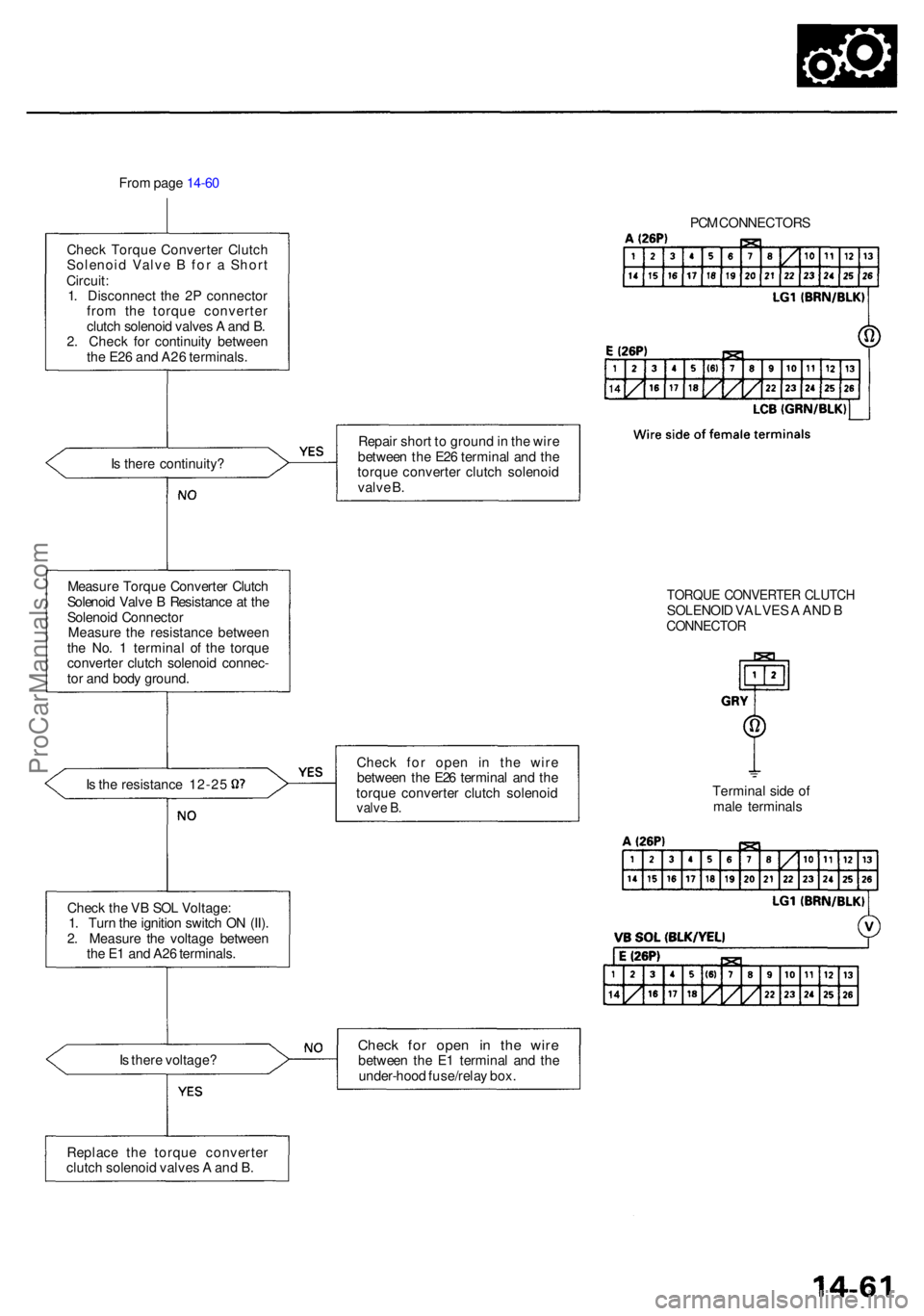
From pag e 14-6 0
Chec k Torqu e Converte r Clutc h
Solenoi d Valv e B fo r a Shor t
Circuit :
1 . Disconnec t th e 2 P connecto r
fro m th e torqu e converte r
clutc h solenoi d valve s A an d B .
2 . Chec k fo r continuit y betwee n
th e E2 6 an d A2 6 terminals .
I s ther e continuity ?
Measur e Torqu e Converte r Clutc h
Solenoi d Valv e B Resistanc e a t th e
Solenoi d Connecto r
Measur e th e resistanc e betwee n
th e No . 1 termina l o f th e torqu e
converte r clutc h solenoi d connec -
to r an d bod y ground .
Is th e resistanc e 12-2 5
Chec k th e V B SO L Voltage :
1 . Tur n th e ignitio n switc h O N (II) .
2 . Measur e th e voltag e betwee n
th e E 1 an d A2 6 terminals .
I s ther e voltage ? PC
M CONNECTOR S
Repai r shor t t o groun d in th e wir e
betwee n th e E2 6 termina l an d th e
torqu e converte r clutc h solenoi d
valv e B .
Chec k fo r ope n i n th e wir e
betwee n th e E2 6 termina l an d th e
torqu e converte r clutc h solenoi d
valve B .
Chec k fo r ope n i n th e wir ebetwee n th e E 1 termina l an d th e
under-hoo d fuse/rela y box .
TORQU E CONVERTE R CLUTC HSOLENOI D VALVE S A AN D BCONNECTO R
Terminal sid e o f
mal e terminal s
Replac e th e torqu e converte r
clutc h solenoi d valve s A an d B .
ProCarManuals.com
Page 769 of 1954
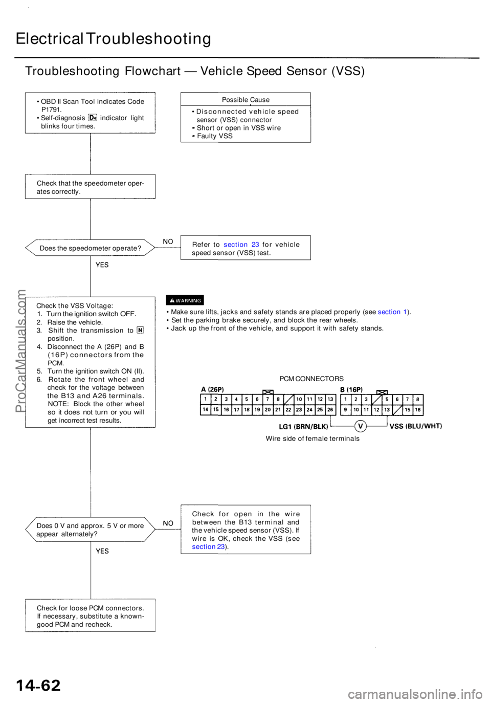
Electrical Troubleshootin g
Troubleshooting Flowchar t — Vehicl e Spee d Senso r (VSS )
• OB D II Sca n Too l indicate s Cod eP1791 .• Self-diagnosi s indicato r ligh t
blink s fou r times .
Possibl e Caus e
• Disconnecte d vehicl e spee dsensor (VSS ) connecto r• Shor t o r ope n in VS S wir e
• Fault y VS S
Chec k tha t th e speedomete r oper -
ate s correctly .
Doe s th e speedomete r operate ? Refe
r t o sectio n 2 3 fo r vehicl e
spee d senso r (VSS ) test .
Chec k th e VS S Voltage :
1. Tur n th e ignitio n switc h OFF .2. Rais e th e vehicle .3. Shif t th e transmissio n t o
position .
4 . Disconnec t th e A (26P ) an d B
(16P ) connector s fro m th ePCM .5. Tur n th e ignitio n switc h O N (II) .
6 . Rotat e th e fron t whee l an d
chec k fo r th e voltag e betwee n
the B1 3 an d A2 6 terminals .NOTE: Bloc k th e othe r whee lso i t doe s no t tur n o r yo u wil lget incorrec t tes t results . •
Mak e sur e lifts , jack s an d safet y stand s ar e place d properl y (se e sectio n 1 ).
• Se t th e parkin g brak e securely , an d bloc k th e rea r wheels .
• Jac k u p th e fron t o f th e vehicle , an d suppor t i t wit h safet y stands .
Doe s 0 V and approx . 5 V or mor e
appea r alternately ? Chec
k fo r ope n i n th e wir e
betwee n th e B1 3 termina l an d
th e vehicl e spee d senso r (VSS) . I f
wir e i s OK , chec k th e VS S (se e
sectio n 23 ).
Chec k fo r loos e PC M connectors .
I f necessary , substitut e a known -
goo d PC M an d recheck . PC
M CONNECTOR S
Wir e sid e o f femal e terminal s
ProCarManuals.com
Page 770 of 1954
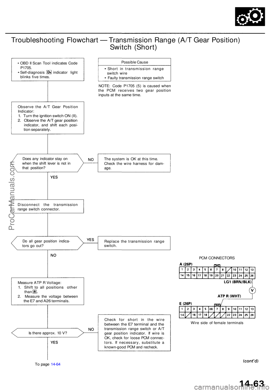
Troubleshooting Flowchar t — Transmissio n Rang e (A/ T Gea r Position )
Switc h (Short )
• OB D II Sca n Too l indicate s Cod eP1705 .• Self-diagnosi s indicato r ligh t
blink s fiv e times . Possibl
e Caus e
• Shor t i n transmissio n rang e
switc h wir e
• Fault y transmissio n rang e switc h
NOTE : Cod e P170 5 (5 ) i s cause d whe n
th e PC M receive s tw o gea r positio n
inputs a t th e sam e time .
Observ e th e A/ T Gea r Positio n
Indicator :
1. Tur n th e ignitio n switc h O N (II) .2. Observ e th e A/ T gea r positio nindicator , an d shif t eac h posi -tion separately .
Does an y indicato r sta y o n
whe n th e shif t leve r i s no t i n
tha t position ? Th
e syste m is O K a t thi s time .
Chec k th e wir e harnes s fo r dam -
age.
Disconnec t th e transmissio n
rang e switc h connector .
D o al l gea r positio n indica -
tor s g o out ? Replac
e th e transmissio n rang e
switch .
PCM CONNECTOR S
Measur e AT P R Voltage :
1. Shif t t o al l position s othe rthan
2 . Measur e th e voltag e betwee n
the E 7 an d A2 6 terminals .
Is ther e approx . 1 0 V ?
To pag e 14-6 4
Chec k fo r shor t i n th e wir ebetwee n th e E 7 termina l an d th etransmissio n rang e switc h o r A/ T
gea r positio n indicator . I f wir e i s
OK , chec k fo r loos e PC M connec -
tors . I f necessary , substitut e a
known-goo d PC M an d recheck . Wir
e sid e o f femal e terminal s
ProCarManuals.com