ACURA RL KA9 1996 Service Repair Manual
Manufacturer: ACURA, Model Year: 1996, Model line: RL KA9, Model: ACURA RL KA9 1996Pages: 1954, PDF Size: 61.44 MB
Page 841 of 1954
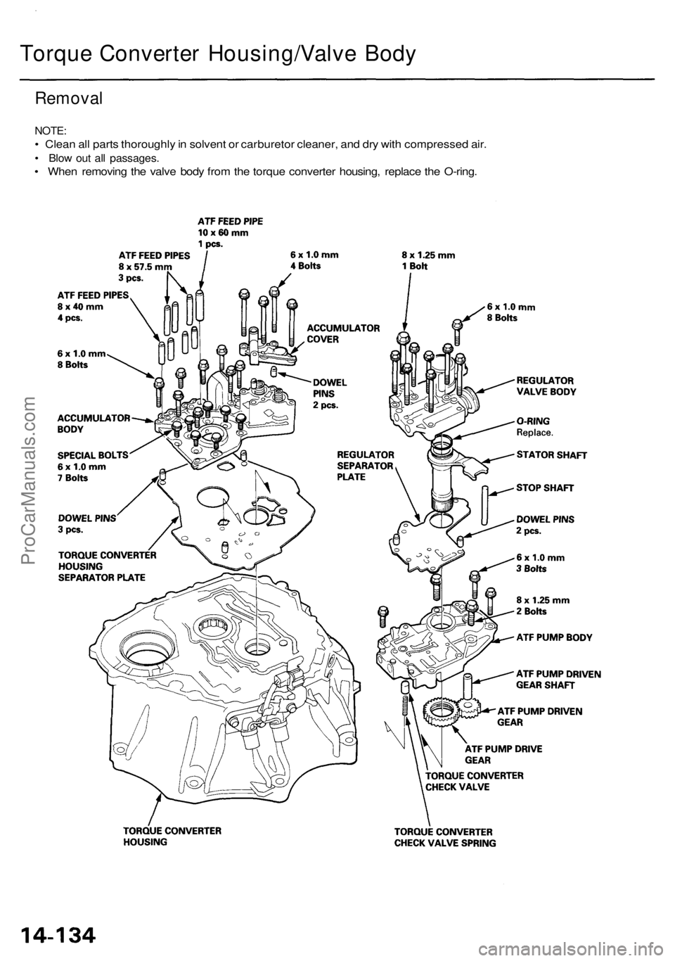
Torque Converter Housing/Valve Body
Removal
NOTE:
• Clean all parts thoroughly in solvent or carburetor cleaner, and dry with compressed air.
• Blow out all passages.
• When removing the valve body from the torque converter housing, replace the O-ring.ProCarManuals.com
Page 842 of 1954
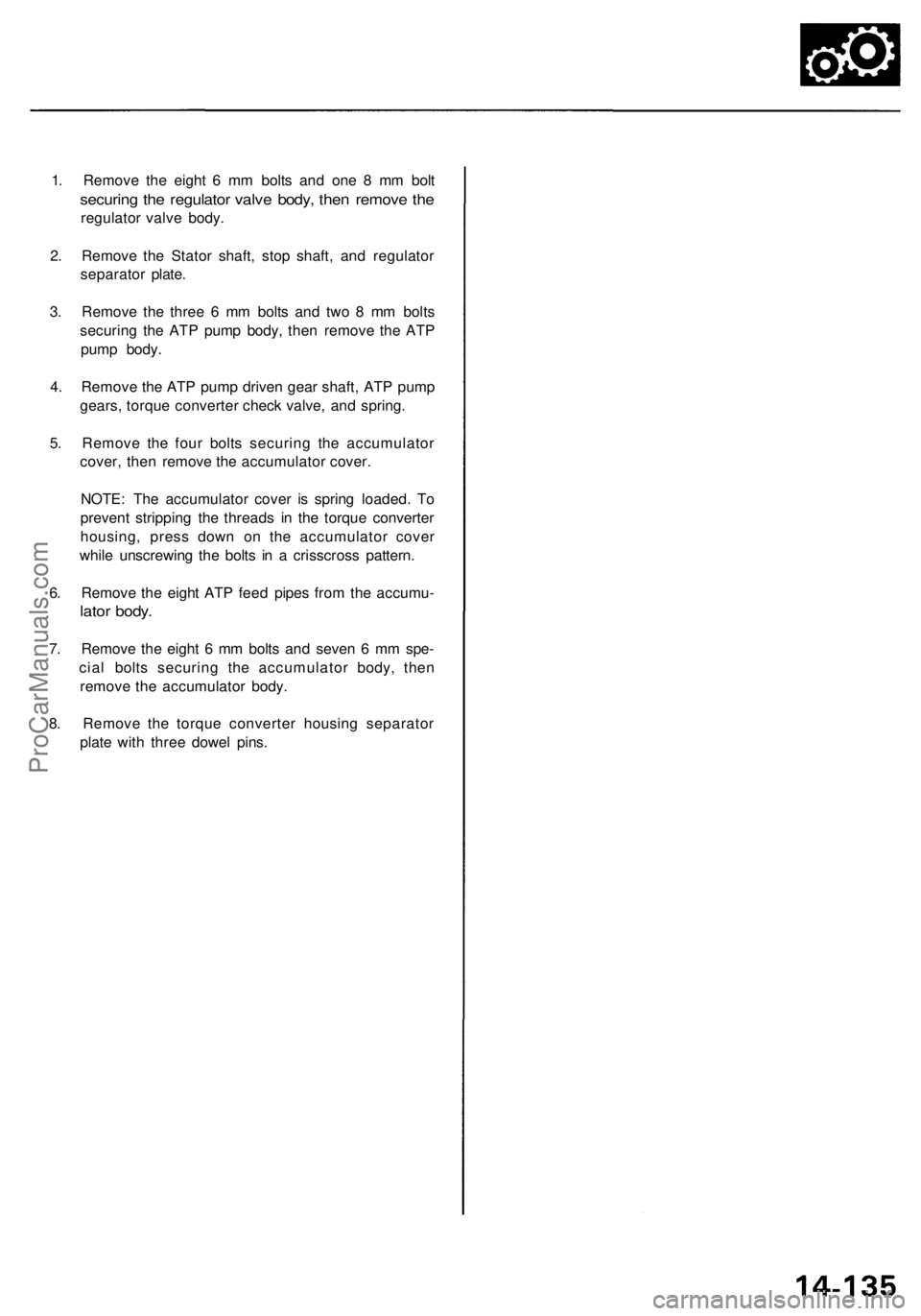
1. Remove the eight 6 mm bolts and one 8 mm bolt
securing the regulator valve body, then remove the
regulator valve body.
2. Remove the Stator shaft, stop shaft, and regulator
separator plate.
3. Remove the three 6 mm bolts and two 8 mm bolts
securing the ATP pump body, then remove the ATP
pump body.
4. Remove the ATP pump driven gear shaft, ATP pump
gears, torque converter check valve, and spring.
5. Remove the four bolts securing the accumulator
cover, then remove the accumulator cover.
NOTE: The accumulator cover is spring loaded. To
prevent stripping the threads in the torque converter
housing, press down on the accumulator cover
while unscrewing the bolts in a crisscross pattern.
6. Remove the eight ATP feed pipes from the accumu-
lator body.
7. Remove the eight 6 mm bolts and seven 6 mm spe-
cial bolts securing the accumulator body, then
remove the accumulator body.
8. Remove the torque converter housing separator
plate with three dowel pins.ProCarManuals.com
Page 843 of 1954
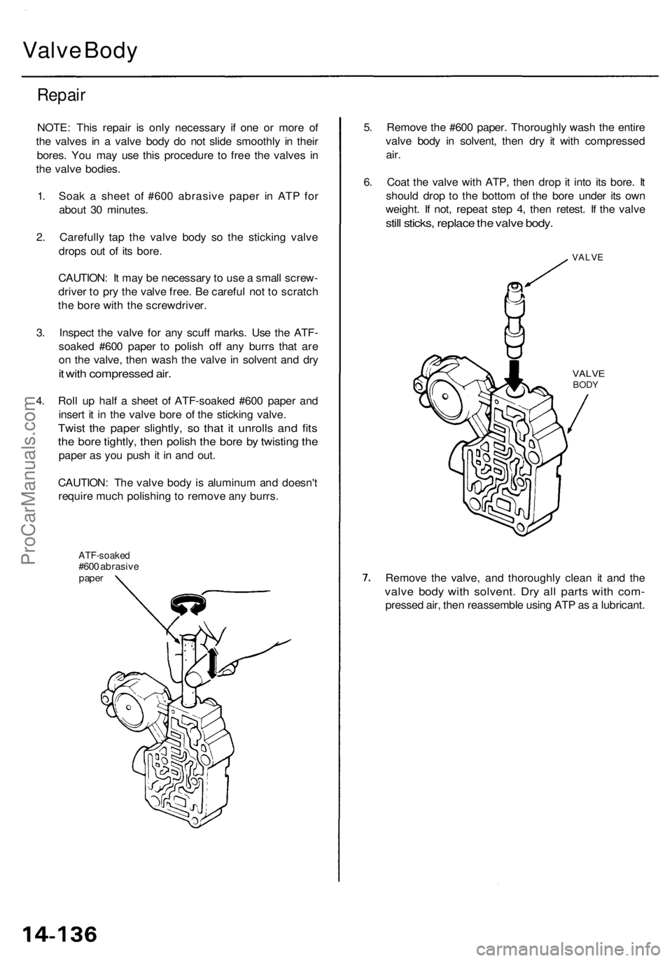
Valve Bod y
Repai r
NOTE : Thi s repai r i s onl y necessar y i f on e o r mor e o f
th e valve s i n a valv e bod y d o no t slid e smoothl y i n thei r
bores . Yo u ma y us e thi s procedur e t o fre e th e valve s i n
th e valv e bodies .
1 . Soa k a shee t o f #60 0 abrasiv e pape r i n AT P fo r
abou t 3 0 minutes .
2 . Carefull y ta p th e valv e bod y s o th e stickin g valv e
drop s ou t o f it s bore .
CAUTION : I t ma y b e necessar y to us e a smal l screw -
drive r t o pr y th e valv e free . B e carefu l no t t o scratc h
th e bor e wit h th e screwdriver .
3 . Inspec t th e valv e fo r an y scuf f marks . Us e th e ATF -
soake d #60 0 pape r t o polis h of f an y burr s tha t ar e
o n th e valve , the n was h th e valv e in solven t an d dr y
it wit h compresse d air .
4. Rol l u p hal f a shee t o f ATF-soake d #60 0 pape r an d
inser t i t i n th e valv e bor e o f th e stickin g valve .
Twist th e pape r slightly , s o tha t i t unroll s an d fit s
the bor e tightly , the n polis h th e bor e b y twistin g th e
pape r a s yo u pus h i t i n an d out .
CAUTION : Th e valv e bod y is aluminu m an d doesn' t
requir e muc h polishin g to remov e an y burrs .
ATF-soake d#600 abrasiv epaper
5. Remov e th e #60 0 paper . Thoroughl y was h th e entir e
valv e bod y i n solvent , the n dr y i t wit h compresse d
air.
6. Coa t th e valv e wit h ATP , the n dro p it int o it s bore . I t
shoul d dro p t o th e botto m o f th e bor e unde r it s ow n
weight . I f not , repea t ste p 4 , the n retest . I f th e valv e
still sticks , replac e th e valv e body .
VALV E
VALVEBODY
Remov e th e valve , an d thoroughl y clea n i t an d th e
valv e bod y wit h solvent . Dr y al l part s wit h com -
presse d air , the n reassembl e usin g AT P a s a lubricant .
ProCarManuals.com
Page 844 of 1954
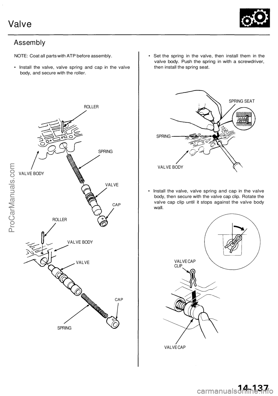
Valve
Assembly
NOTE: Coat all parts with ATP before assembly.
• Install the valve, valve spring and cap in the valve
body, and secure with the roller.
ROLLER
SPRING
VALVE BODY
VALVE
CAP
CAP
SPRING
• Set the spring in the valve, then install them in the
valve body. Push the spring in with a screwdriver,
then install the spring seat.
SPRING SEAT
SPRING
VALVE BODY
• Install the valve, valve spring and cap in the valve
body, then secure with the valve cap clip. Rotate the
valve cap clip until it stops against the valve body
wall.
VALVE CAP
CLIP
VALVE CAP
ROLLER
VALVE BODY
VALVEProCarManuals.com
Page 845 of 1954
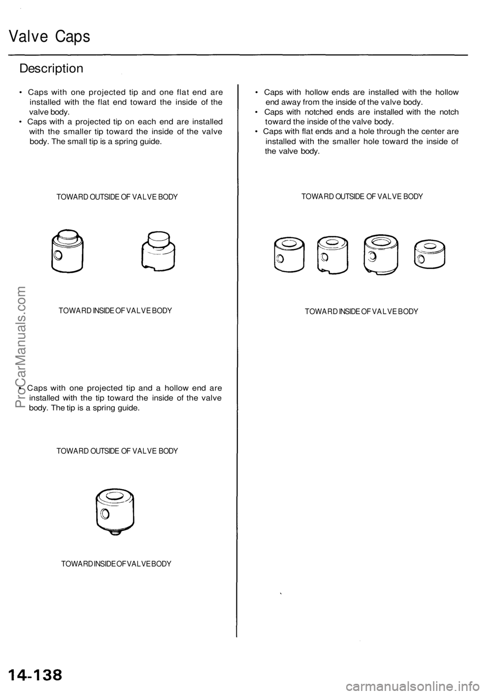
Valve Cap s
Descriptio n
• Cap s wit h on e projecte d ti p an d on e fla t en d ar e
installe d wit h th e fla t en d towar d th e insid e o f th e
valv e body .
• Cap s wit h a projecte d ti p o n eac h en d ar e installe d
wit h th e smalle r ti p towar d th e insid e o f th e valv e
body . Th e smal l ti p is a sprin g guide .
TOWAR D OUTSID E O F VALV E BOD Y
TOWAR D INSID E O F VALV E BOD Y
• Cap s wit h on e projecte d ti p an d a hollo w en d ar e
installe d wit h th e ti p towar d th e insid e o f th e valv e
body . Th e ti p is a sprin g guide .
TOWAR D OUTSID E O F VALV E BOD Y
TOWAR D INSID E O F VALV E BOD Y
• Cap s wit h hollo w end s ar e installe d wit h th e hollo w
en d awa y fro m th e insid e o f th e valv e body .
• Cap s wit h notche d end s ar e installe d wit h th e notc h
towar d th e insid e o f th e valv e body .
• Cap s wit h fla t end s an d a hol e throug h th e cente r ar e
installe d wit h th e smalle r hol e towar d th e insid e o f
th e valv e body .
TOWAR D OUTSID E O F VALV E BOD Y
TOWAR D INSID E O F VALV E BOD Y
ProCarManuals.com
Page 846 of 1954
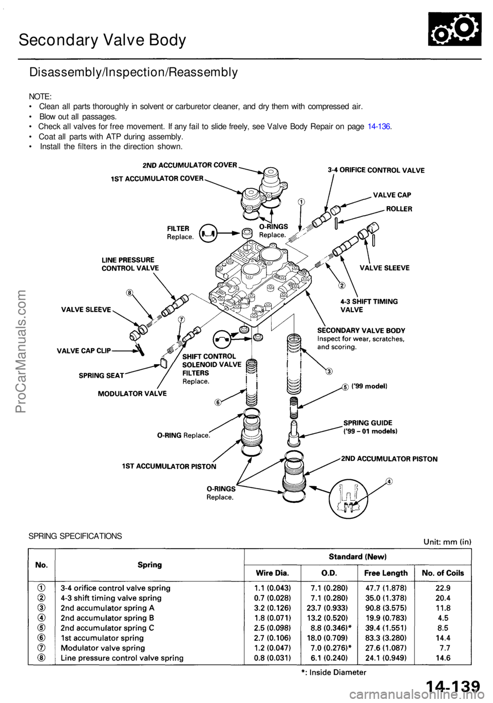
Secondary Valv e Bod y
SPRIN G SPECIFICATION S
Disassembly/lnspection/Reassembl y
NOTE:
• Clea n al l part s thoroughl y i n solven t o r carbureto r cleaner , an d dr y the m wit h compresse d air .
• Blo w ou t al l passages .
• Chec k al l valve s fo r fre e movement . I f an y fai l t o slid e freely , se e Valv e Bod y Repai r o n pag e 14-136 .
• Coa t al l part s wit h AT P durin g assembly .
• Instal l th e filter s i n th e directio n shown .
ProCarManuals.com
Page 847 of 1954
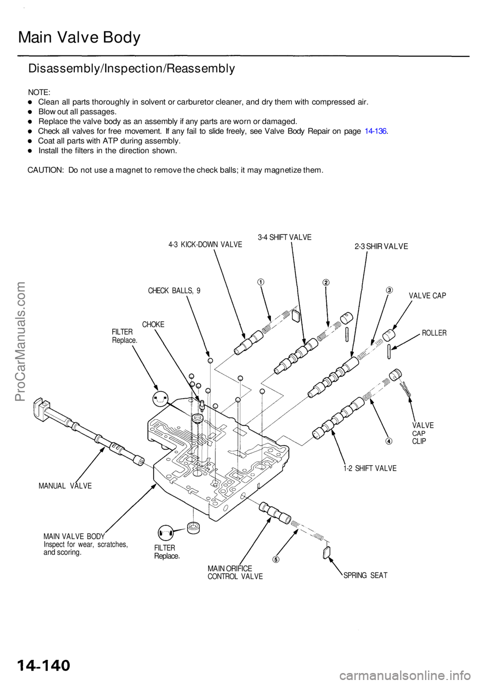
Main Valv e Bod y
Disassembly/Inspection/Reassembl y
NOTE:
Clean al l part s thoroughl y in solven t o r carbureto r cleaner , an d dr y the m wit h compresse d air .
Blo w ou t al l passages .
Replac e th e valv e bod y a s a n assembl y if an y part s ar e wor n o r damaged .
Chec k al l valve s fo r fre e movement . I f an y fai l t o slid e freely , se e Valv e Bod y Repai r o n pag e 14-136 .
Coa t al l part s wit h AT P durin g assembly .
Instal l th e filter s i n th e directio n shown .
CAUTION : D o no t us e a magne t t o remov e th e chec k balls ; i t ma y magnetiz e them .
4-3 KICK-DOW N VALV E3-4 SHIF T VALV E
MANUA L VALV E
MAI N VALV E BOD Y
Inspec t fo r wear , scratches ,
and scoring .FILTERReplac e
MAIN ORIFIC ECONTRO L VALV E
2-3 SHI R VALV E
VALVE CA P
ROLLE R
VALVECAPCLI P
SPRIN G SEA T
1-
2 SHIF T VALV E
FILTE
R
Replace .CHOK
E
CHEC
K BALLS , 9
ProCarManuals.com
Page 848 of 1954
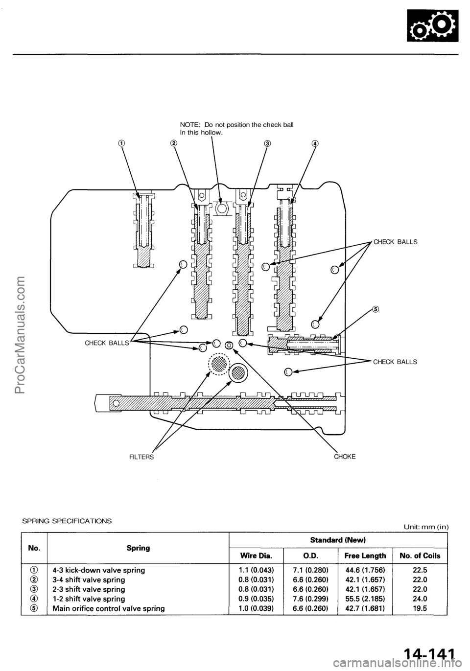
NOTE: Do not position the check ball
in this hollow.
CHECK BALLS
CHECK BALLS
FILTERS
CHOKE
SPRING SPECIFICATIONS
Unit: mm (in)
CHECK BALLSProCarManuals.com
Page 849 of 1954
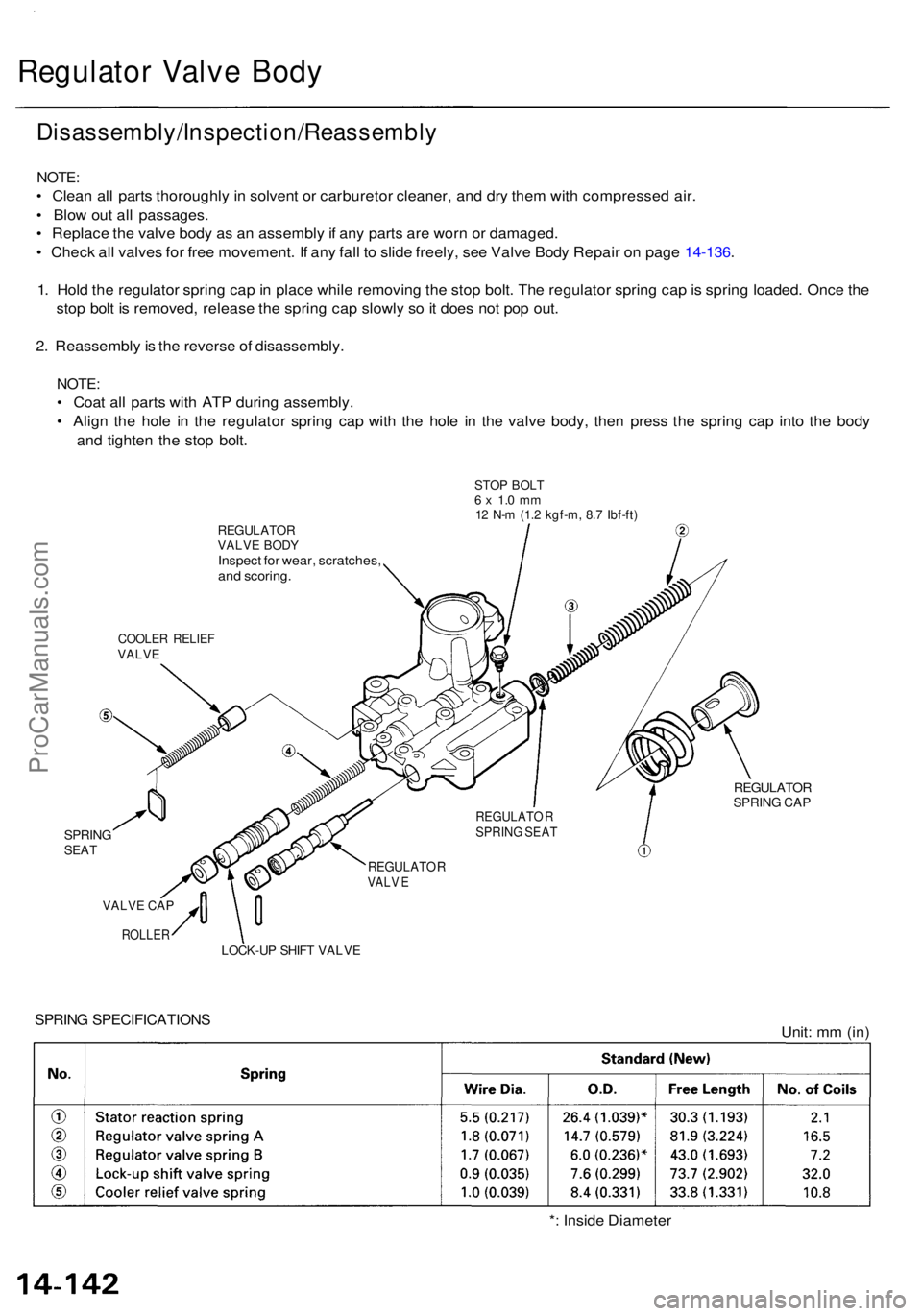
Regulator Valv e Bod y
Disassembly/Inspection/Reassembl y
NOTE:
• Clea n al l part s thoroughl y i n solven t o r carbureto r cleaner , an d dr y the m wit h compresse d air .
• Blo w ou t al l passages .
• Replac e th e valv e bod y a s a n assembl y if an y part s ar e wor n o r damaged .
• Chec k al l valve s fo r fre e movement . I f an y fal l t o slid e freely , se e Valv e Bod y Repai r o n pag e 14-136 .
1 . Hol d th e regulato r sprin g ca p in plac e whil e removin g th e sto p bolt . Th e regulato r sprin g ca p is sprin g loaded . Onc e th e
sto p bol t i s removed , releas e th e sprin g ca p slowl y s o it doe s no t po p out .
2 . Reassembl y is th e revers e o f disassembly .
NOTE:
• Coa t al l part s wit h AT P durin g assembly .
• Alig n th e hol e i n th e regulato r sprin g cap with th e hol e i n th e valv e body , the n pres s th e sprin g cap into th e bod y
an d tighte n th e sto p bolt .
REGULATO RVALVE BOD YInspec t fo r wear , scratches ,
an d scoring .
STOP BOL T6 x 1. 0 m m12 N- m (1. 2 kgf-m , 8. 7 Ibf-ft )
COOLE R RELIE FVALVE
SPRIN GSEAT
REGULATO RSPRING CA P
VALV E CA P
LOCK-U P SHIF T VALV E
SPRING SPECIFICATION SUnit: m m (in )
* : Insid e Diamete r
REGULATO RVALV E
REGULATO RSPRING SEAT
ROLLER
ProCarManuals.com
Page 850 of 1954
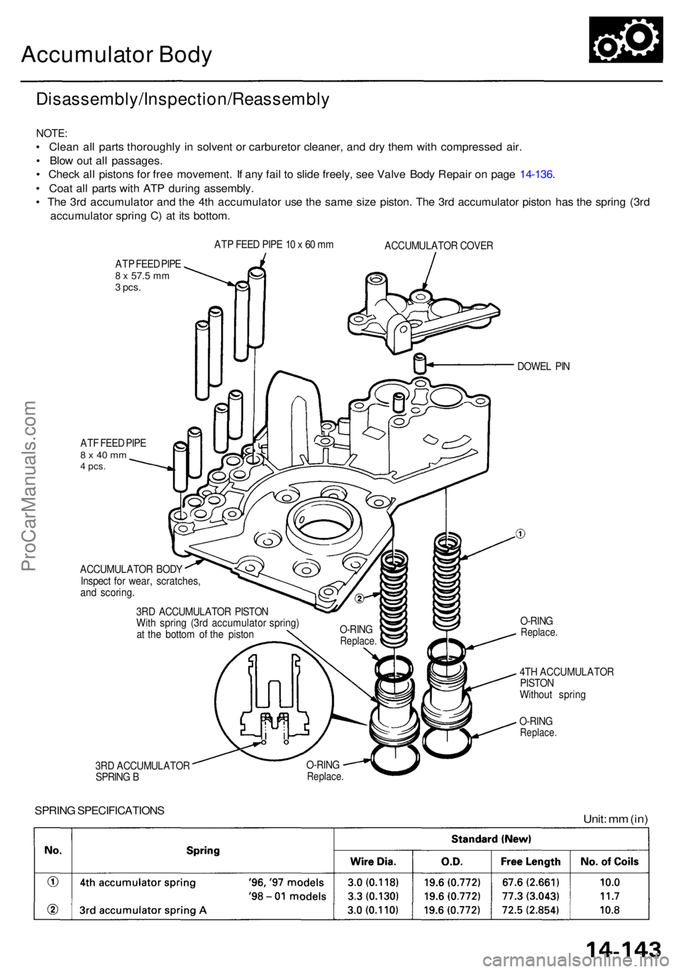
Accumulator Bod y
Disassembly/Inspection/Reassembl y
NOTE:
• Clea n al l part s thoroughl y i n solven t o r carbureto r cleaner , an d dr y the m wit h compresse d air .
• Blo w ou t al l passages .
• Chec k al l piston s fo r fre e movement . I f an y fai l t o slid e freely , se e Valv e Bod y Repai r o n pag e 14-136 .
• Coa t al l part s wit h AT P durin g assembly .
• Th e 3r d accumulato r an d th e 4t h accumulato r us e th e sam e siz e piston . Th e 3r d accumulato r pisto n ha s th e sprin g (3r d
accumulato r sprin g C ) a t it s bottom .
ATP FEE D PIP E8 x 57. 5 mm3 pcs .
ATP FEE D PIP E 1 0 x 60 m m
ACCUMULATO R COVE R
AT F FEE D PIP E
8 x 40 m m4 pcs .
ACCUMULATO R BOD Y
Inspec t fo r wear , scratches,
an d scoring .
3R D ACCUMULATO R PISTO N
Wit h sprin g (3r d accumulato r spring )
a t th e botto m o f th e pisto n DOWE
L PI N
O-RIN G
Replace .
4TH ACCUMULATO R
PISTO N
Withou t sprin g
O-RIN G
Replace .
3RD ACCUMULATO R
SPRIN G B O-RIN
GReplace .
SPRING SPECIFICATION SUnit: m m (in )
O-RIN GReplace .
ProCarManuals.com