ACURA RL KA9 1996 Service Repair Manual
Manufacturer: ACURA, Model Year: 1996, Model line: RL KA9, Model: ACURA RL KA9 1996Pages: 1954, PDF Size: 61.44 MB
Page 981 of 1954
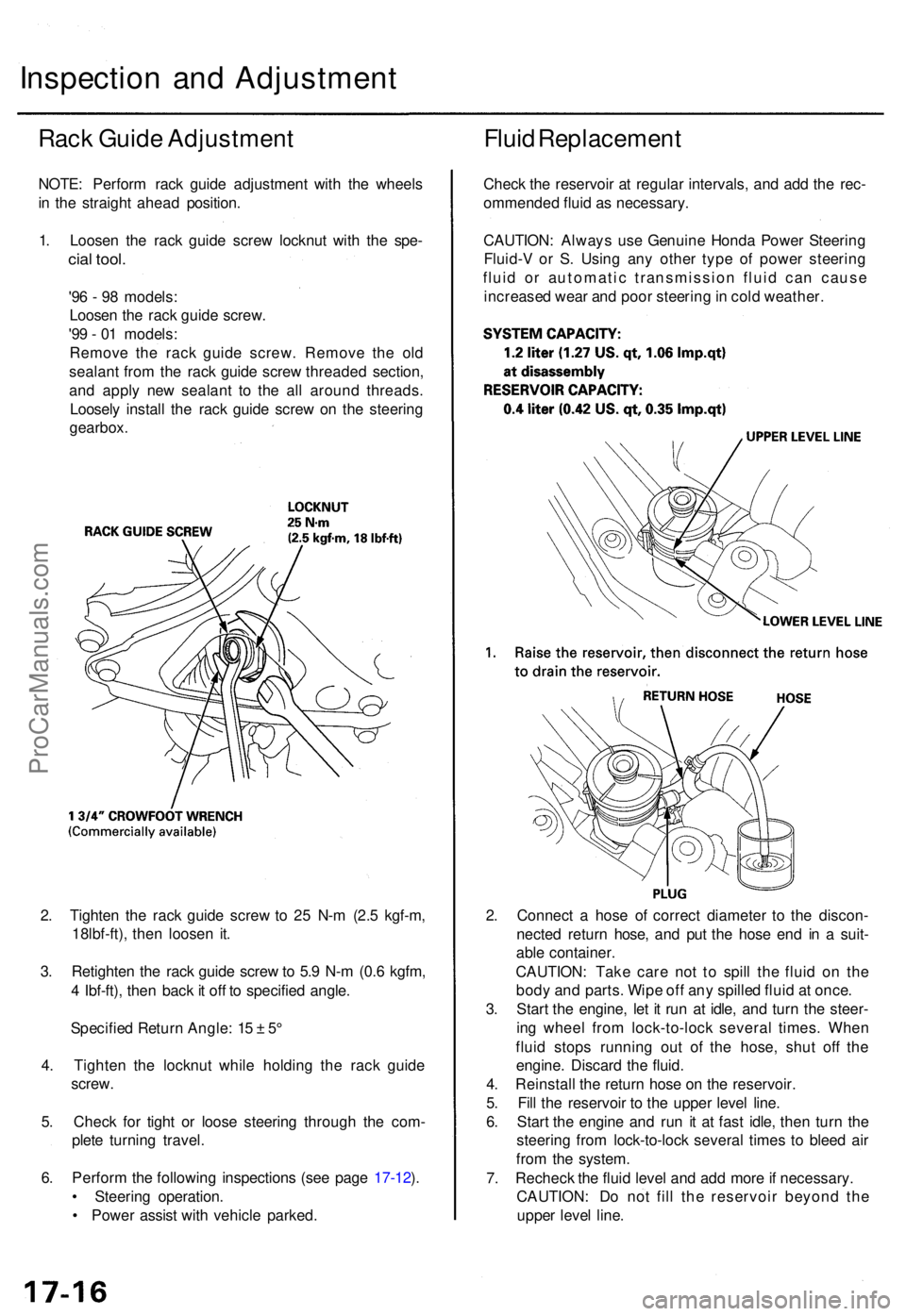
2. Tighte n th e rac k guid e scre w to 2 5 N- m (2. 5 kgf-m ,
18lbf-ft) , the n loose n it .
3 . Retighte n th e rac k guid e scre w to 5. 9 N- m (0. 6 kgfm ,
4 Ibf-ft) , the n bac k it of f t o specifie d angle .
Specifie d Retur n Angle : 1 5 ± 5°
4 . Tighte n th e locknu t whil e holdin g th e rac k guid e
screw .
5 . Chec k fo r tigh t o r loos e steerin g throug h th e com -
plet e turnin g travel .
6 . Perfor m th e followin g inspection s (se e pag e 17-12 ).
• Steerin g operation .
• Powe r assis t wit h vehicl e parked . 2
. Connec t a hos e o f correc t diamete r t o th e discon -
necte d retur n hose , an d pu t th e hos e en d i n a suit -
abl e container .
CAUTION : Tak e car e no t t o spil l th e flui d o n th e
bod y an d parts . Wip e of f an y spille d flui d a t once .
3 . Star t th e engine , le t i t ru n a t idle , an d tur n th e steer -
in g whee l fro m lock-to-loc k severa l times . Whe n
flui d stop s runnin g ou t of the hose , shu t of f th e
engine . Discar d th e fluid .
4 . Reinstal l th e retur n hos e o n th e reservoir .
5 . Fil l th e reservoi r t o th e uppe r leve l line .
6 . Star t th e engin e an d ru n i t a t fas t idle , the n tur n th e
steerin g fro m lock-to-loc k severa l time s t o blee d ai r
fro m th e system .
7 . Rechec k th e flui d leve l an d ad d mor e if necessary .
CAUTION : D o no t fil l th e reservoi r beyon d th e
uppe r leve l line .
Inspectio n an d Adjustmen t
Rack Guid e Adjustmen t
NOTE: Perfor m rac k guid e adjustmen t wit h th e wheel s
i n th e straigh t ahea d position .
1 . Loose n th e rac k guid e scre w locknu t wit h th e spe -
cial tool .
'96 - 9 8 models :
Loose n th e rac k guid e screw .
'9 9 - 0 1 models :
Remov e th e rac k guid e screw . Remov e th e ol d
sealan t fro m th e rac k guid e scre w threade d section ,
an d appl y ne w sealan t t o th e al l aroun d threads .
Loosel y instal l th e rac k guid e scre w o n th e steerin g
gearbox .
Fluid Replacemen t
Check th e reservoi r a t regula r intervals , an d ad d th e rec -
ommende d flui d a s necessary .
CAUTION : Alway s us e Genuin e Hond a Powe r Steerin g
Fluid- V o r S . Usin g an y othe r typ e o f powe r steerin g
flui d o r automati c transmissio n flui d ca n caus e
increase d wea r an d poo r steerin g in col d weather .
ProCarManuals.com
Page 982 of 1954
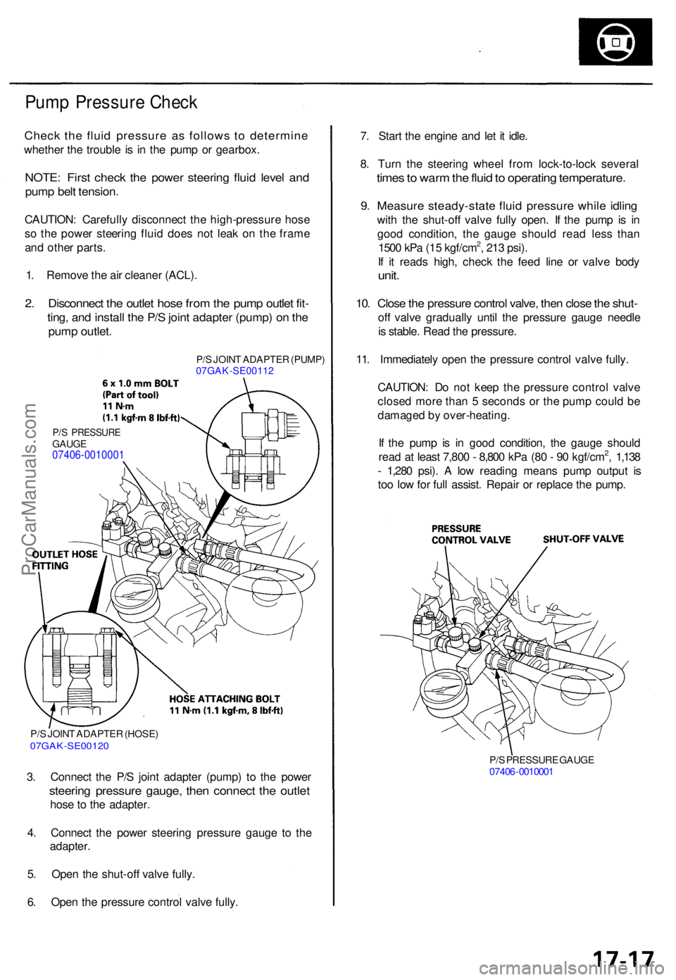
Pump Pressur e Chec k
Check th e flui d pressur e a s follow s t o determin e
whether th e troubl e i s i n th e pum p o r gearbox .
NOTE: Firs t chec k th e powe r steerin g flui d leve l an d
pum p bel t tension .
CAUTION : Carefull y disconnec t th e high-pressur e hos e
s o th e powe r steerin g flui d doe s no t lea k o n th e fram e
an d othe r parts .
1 . Remov e th e ai r cleane r (ACL) .
2. Disconnec t th e outle t hos e fro m th e pum p outle t fit -
ting , an d instal l th e P/ S join t adapte r (pump ) o n th e
pum p outlet .
P/S JOIN T ADAPTE R (PUMP )
07GAK-SE0011 2
P/S PRESSUR EGAUGE07406-0010001
P/S JOIN T ADAPTE R (HOSE )07GAK-SE0012 0
3. Connec t th e P/ S join t adapte r (pump ) t o th e powe r
steerin g pressur e gauge , the n connec t th e outle t
hose t o th e adapter .
4 . Connec t th e powe r steerin g pressur e gaug e t o th e
adapter .
5 . Ope n th e shut-of f valv e fully .
6 . Ope n th e pressur e contro l valv e fully .
P/S PRESSUR E GAUG E
0740 6-001000 1
7. Star t th e engin e an d le t i t idle .
8 . Tur n th e steerin g whee l fro m lock-to-loc k severa l
times to war m th e flui d to operatin g temperature .
9. Measur e steady-stat e flui d pressur e whil e idlin g
with th e shut-of f valv e full y open . I f th e pum p i s i n
goo d condition , th e gaug e shoul d rea d les s tha n
150 0 kP a (1 5 kgf/cm
2, 21 3 psi) .
I f i t read s high , chec k th e fee d lin e o r valv e bod y
unit.
10. Clos e th e pressur e contro l valve , the n clos e th e shut -
off valv e graduall y unti l th e pressur e gaug e needl e
i s stable . Rea d th e pressure .
11 . Immediatel y ope n th e pressur e contro l valv e fully .
CAUTION : D o no t kee p th e pressur e contro l valv e
close d mor e tha n 5 second s o r th e pum p coul d b e
damage d b y over-heating .
I f th e pum p i s i n goo d condition , th e gaug e shoul d
rea d a t leas t 7,80 0 - 8,80 0 kP a (8 0 - 9 0 kgf/cm
2, 1,13 8
- 1,28 0 psi) . A lo w readin g mean s pum p outpu t i s
to o lo w fo r ful l assist . Repai r o r replac e th e pump .
ProCarManuals.com
Page 983 of 1954
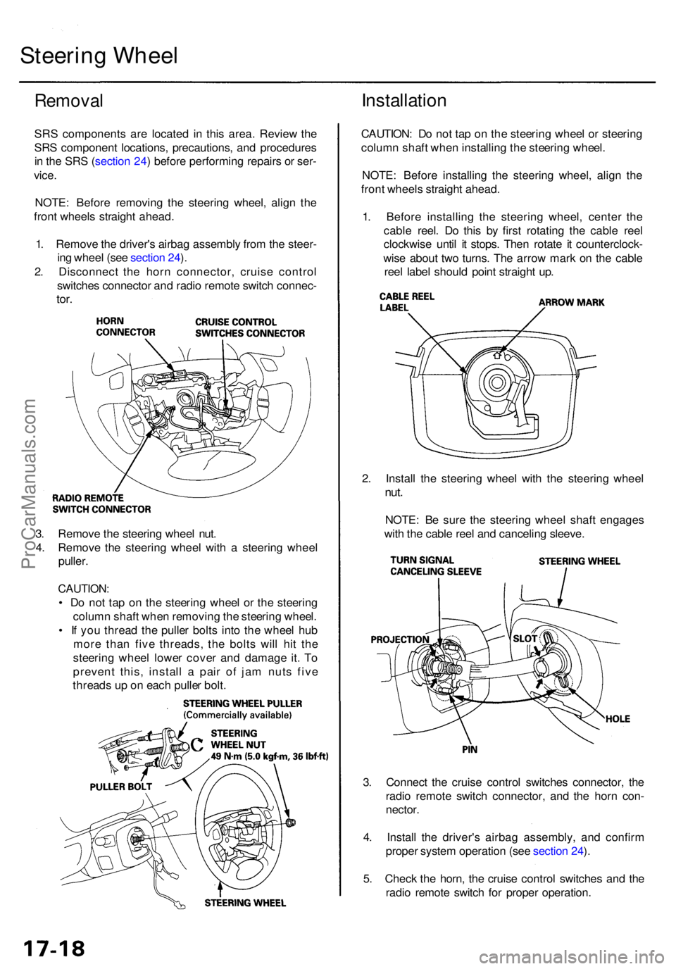
3. Connec t th e cruis e contro l switche s connector , th e
radi o remot e switc h connector , an d th e hor n con -
nector .
4 . Instal l th e driver' s airba g assembly , an d confir m
prope r syste m operatio n (se e sectio n 24 ).
5 . Chec k th e horn , th e cruis e contro l switche s an d th e
radi o remot e switc h fo r prope r operation .
3
. Remov e th e steerin g whee l nut .
4 . Remov e th e steerin g whee l wit h a steerin g whee l
puller .
CAUTION :
• D o no t ta p o n th e steerin g whee l o r th e steerin g
colum n shaf t whe n removin g th e steerin g wheel .
• I f yo u threa d th e pulle r bolt s int o th e whee l hu b
mor e tha n fiv e threads , th e bolt s wil l hi t th e
steerin g whee l lowe r cove r an d damag e it . T o
preven t this , instal l a pai r o f ja m nut s fiv e
thread s u p o n eac h pulle r bolt . 2
. Instal l th e steerin g whee l wit h th e steerin g whee l
nut.
NOTE : B e sur e th e steerin g whee l shaf t engage s
wit h th e cabl e ree l an d cancelin g sleeve .
Remova l
SRS component s ar e locate d i n thi s area . Revie w th e
SR S componen t locations , precautions , an d procedure s
i n th e SR S (sectio n 24 ) befor e performin g repair s o r ser -
vice .
NOTE : Befor e removin g th e steerin g wheel , alig n th e
fron t wheel s straigh t ahead .
1 . Remov e th e driver' s airba g assembl y fro m th e steer -
in g whee l (se e sectio n 24 ).
2 . Disconnec t th e hor n connector , cruis e contro l
switche s connecto r an d radi o remot e switc h connec -
tor.
Installatio n
CAUTION : D o no t ta p o n th e steerin g whee l o r steerin g
colum n shaf t whe n installin g th e steerin g wheel .
NOTE : Befor e installin g th e steerin g wheel , alig n th e
fron t wheel s straigh t ahead .
1 . Befor e installin g th e steerin g wheel , cente r th e
cabl e reel . D o thi s b y firs t rotatin g th e cabl e ree l
clockwis e unti l i t stops . The n rotat e i t counterclock -
wis e abou t tw o turns . Th e arro w mar k o n th e cabl e
ree l labe l shoul d poin t straigh t up .
Steerin g Whee l
ProCarManuals.com
Page 984 of 1954
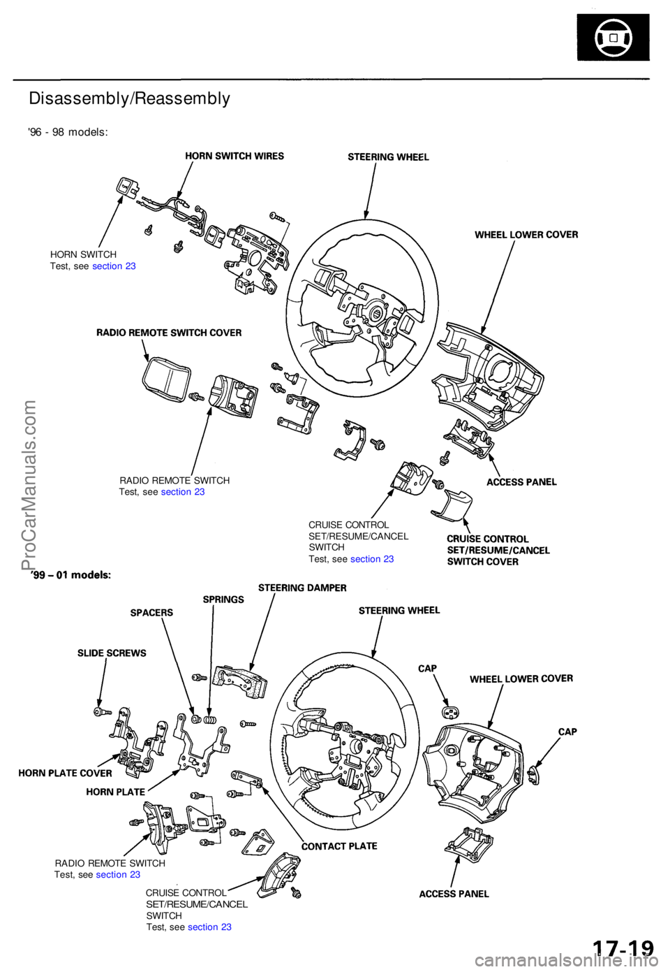
Disassembly/Reassembly
'96 - 9 8 models :
HORN SWITC H
Test , se e sectio n 2 3
CRUISE CONTRO L
SET/RESUME/CANCE L
SWITC H
Test , se e sectio n 2 3
RADI
O REMOT E SWITC H
Test , se e sectio n 2 3
RADI O REMOT E SWITC H
Test , se e sectio n 2 3
CRUIS E CONTRO L
SET/RESUME/CANCE LSWITCH
Test , se e sectio n 2 3
ProCarManuals.com
Page 985 of 1954
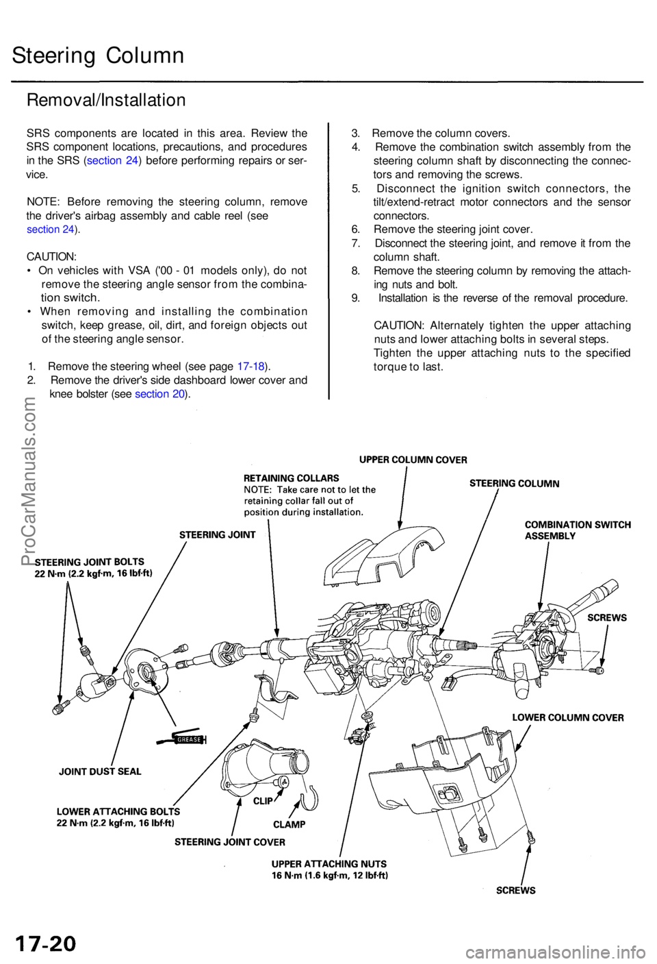
Steering Colum n
Removal/Installatio n
SRS component s ar e locate d i n thi s area . Revie w th e
SR S componen t locations , precautions , an d procedure s
i n th e SR S (sectio n 24 ) befor e performin g repair s o r ser -
vice .
NOTE : Befor e removin g th e steerin g column , remov e
th e driver' s airba g assembl y an d cabl e ree l (se e
section 24 ).
CAUTION :
• O n vehicle s wit h VS A ('0 0 - 0 1 model s only) , d o no t
remov e th e steerin g angl e senso r fro m th e combina -
tion switch .
• Whe n removin g an d installin g th e combinatio n
switch , kee p grease , oil , dirt , an d foreig n object s ou t
o f th e steerin g angl e sensor .
1 . Remov e th e steerin g whee l (se e pag e 17-18 ).
2 . Remov e th e driver' s sid e dashboar d lowe r cove r an d
kne e bolste r (se e sectio n 20 ). 3
. Remov e th e colum n covers .
4 . Remov e th e combinatio n switc h assembl y fro m th e
steerin g colum n shaf t b y disconnectin g th e connec -
tor s an d removin g th e screws .
5 . Disconnec t th e ignitio n switc h connectors , th e
tilt/extend-retrac t moto r connector s an d th e senso r
connectors .
6 . Remov e th e steerin g join t cover .
7 . Disconnec t th e steerin g joint , an d remov e it fro m th e
colum n shaft .
8 . Remov e th e steerin g colum n b y removin g th e attach -
in g nut s an d bolt .
9 . Installatio n i s th e revers e o f th e remova l procedure .
CAUTION : Alternatel y tighte n th e uppe r attachin g
nut s an d lowe r attachin g bolt s in severa l steps .
Tighte n th e uppe r attachin g nut s t o th e specifie d
torqu e to last .
ProCarManuals.com
Page 986 of 1954
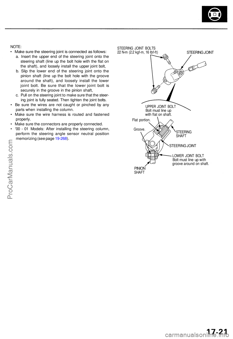
NOTE:
• Mak e sur e th e steerin g join t i s connecte d a s follows :
a. Inser t th e uppe r en d o f th e steerin g join t ont o th e
steerin g shaf t (lin e u p th e bol t hol e wit h th e fla t o n
th e shaft) , an d loosel y instal l th e uppe r join t bolt ,
b . Sli p th e lowe r en d o f th e steerin g join t ont o th e
pinio n shaf t (lin e u p th e bol t hol e wit h th e groov e
aroun d th e shaft) , an d loosel y instal l th e lowe r
joint bolt . B e sur e tha t th e lowe r join t bol t i s
securel y i n th e groov e in th e pinio n shaft ,
c . Pul l o n th e steerin g join t t o mak e sur e tha t th e steer -
in g join t i s full y seated . The n tighte n th e join t bolts .
• B e sur e th e wire s ar e no t caugh t o r pinche d b y an y
part s whe n installin g th e column .
• Mak e sur e th e wir e harnes s i s route d an d fastene d
properly .
• Mak e sur e th e connector s ar e properl y connected .
• '0 0 - 0 1 Models : Afte r installin g th e steerin g column ,
perfor m th e steerin g angl e senso r neutra l positio n
memorizin g (se e pag e 19-268 ).
STEERIN G JOIN T BOLT S22 N- m (2. 2 kgf-m , 1 6 Ibf-ft )STEERIN G JOIN T
UPPE R JOIN T BOL TBolt mus t lin e u pwit h fla t o n shaft .
Flat portion .
Groove.
STEERING
SHAF T
STEERIN G JOIN T
LOWE R JOIN T BOL TBolt mus t lin e u p wit hgroov e aroun d o n shaft .
PINIONSHAF T
ProCarManuals.com
Page 987 of 1954
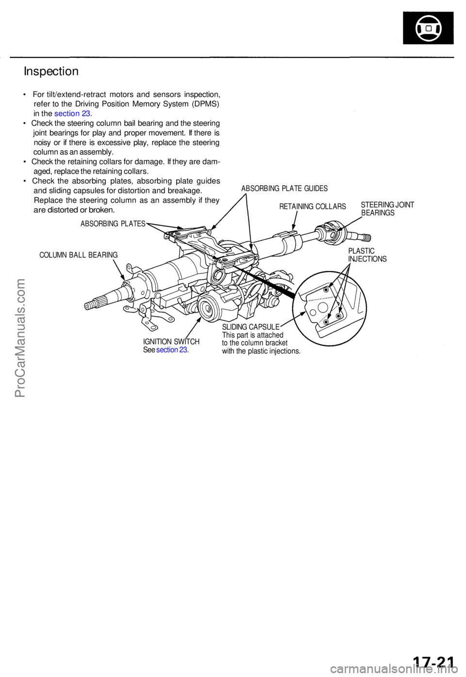
Inspection
• Fo r tilt/extend-retrac t motor s an d sensor s inspection ,
refe r t o th e Drivin g Positio n Memor y Syste m (DPMS )
i n th e sectio n 23 .
• Chec k th e steerin g colum n bai l bearin g an d th e steerin g
join t bearing s fo r pla y an d prope r movement . I f ther e is
nois y o r i f ther e is excessiv e play , replac e th e steerin g
colum n a s a n assembly .
• Chec k th e retainin g collar s fo r damage . I f the y ar e dam -
aged , replac e th e retainin g collars .
• Chec k th e absorbin g plates , absorbin g plat e guide s
an d slidin g capsule s fo r distortio n an d breakage .
Replac e th e steerin g colum n a s a n assembl y i f the y
are distorte d o r broken .
ABSORBIN G PLATE S
COLUMN BAL L BEARIN G
ABSORBIN G PLAT E GUIDE S
STEERIN G JOIN TBEARING S
PLASTICINJECTION S
IGNITION SWITC HSee sectio n 23 .
SLIDIN G CAPSUL EThis par t i s attache dto th e colum n bracke twith th e plasti c injections .
RETAININ G COLLAR S
ProCarManuals.com
Page 988 of 1954
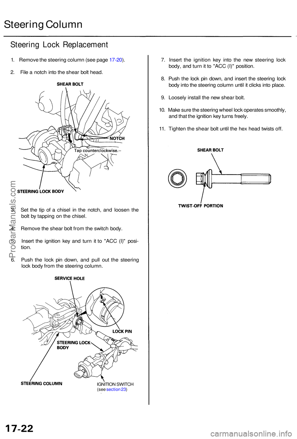
Steering Loc k Replacemen t
1. Remov e th e steerin g colum n (se e pag e 17-20 ).
2 . Fil e a notc h int o th e shea r bol t head .
Steerin g Colum n
7. Inser t th e ignitio n ke y int o th e ne w steerin g loc k
body , an d tur n it t o "AC C (I) " position .
8 . Pus h th e loc k pi n down , an d inser t th e steerin g loc k
bod y int o th e steerin g colum n unti l i t click s int o place .
9 . Loosel y instal l th e ne w shea r bolt .
10 . Mak e sur e th e steerin g whee l loc k operate s smoothly ,
an d tha t th e ignitio n ke y turn s freely .
11 . Tighte n th e shea r bol t unti l th e he x hea d twist s off .
3 . Se t th e ti p o f a chise l i n th e notch , an d loose n th e
bol t b y tappin g o n th e chisel .
4 . Remov e th e shea r bol t fro m th e switc h body .
5 . Inser t th e ignitio n ke y an d tur n i t t o "AC C (I) " posi -
tion.
6. Pus h th e loc k pi n down , an d pul l ou t th e steerin g
loc k bod y fro m th e steerin g column .
IGNITION SWITC H(see sectio n 23 )
ProCarManuals.com
Page 989 of 1954
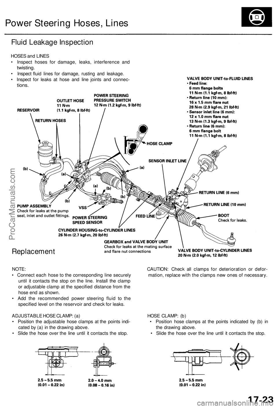
Power Steering Hoses, Lines
Fluid Leakage Inspection
HOSES and LINES
• Inspect hoses for damage, leaks, interference and
twisting.
• Inspect fluid lines for damage, rusting and leakage.
• Inspect for leaks at hose and line joints and connec-
tions.
Replacement
NOTE: CAUTION: Check all clamps for deterioration or defor-
• Connect each hose to the corresponding line securely mation, replace with the clamps new ones of necessary.
until it contacts the stop on the line. Install the clamp
or adjustable clamp at the specified distance from the
hose end as shown.
• Add the recommended power steering fluid to the
specified level on the reservoir and check for leaks.
ADJUSTABLE HOSE CLAMP: (a) HOSE CLAMP: (b)
• Position the adjustable hose clamps at the points indi- • Position hose clamps at the points indicated by (b) in
cated by (a) in the drawing above. the drawing above.
• Slide the hose over the line until it contacts the stop. • Slide the hose over the line until it contacts the stop.ProCarManuals.com
Page 990 of 1954
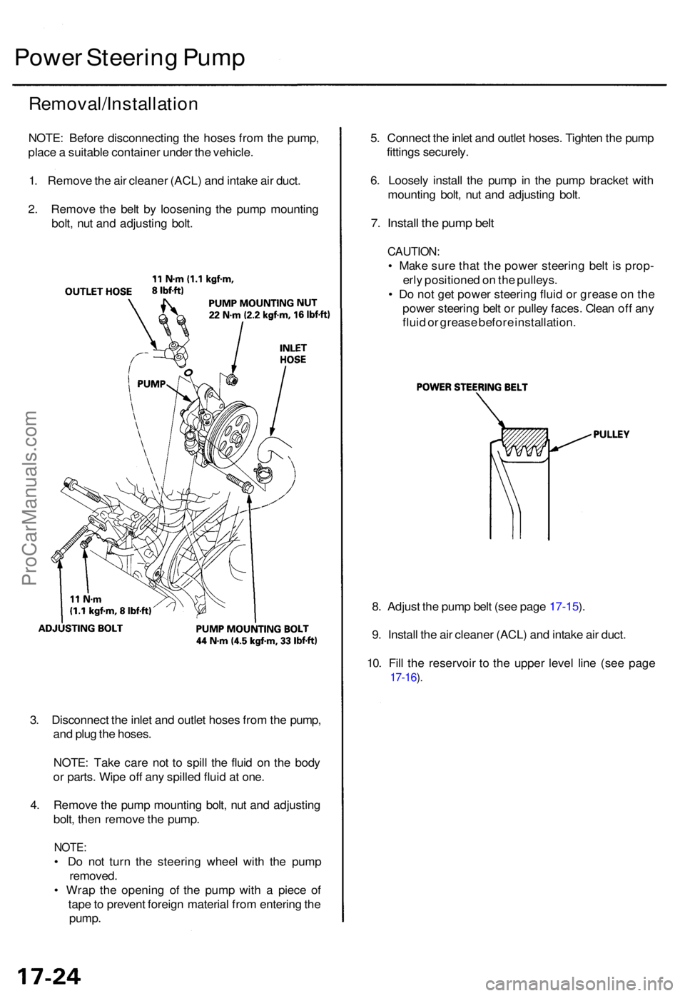
Power Steerin g Pum p
Removal/Installatio n
NOTE: Befor e disconnectin g th e hose s fro m th e pump ,
plac e a suitabl e containe r unde r th e vehicle .
1 . Remov e th e ai r cleane r (ACL ) an d intak e ai r duct .
2 . Remov e th e bel t b y loosenin g th e pum p mountin g
bolt , nu t an d adjustin g bolt . 5
. Connec t th e inle t an d outle t hoses . Tighte n th e pum p
fitting s securely .
6 . Loosel y instal l th e pum p i n th e pum p bracke t wit h
mountin g bolt , nu t an d adjustin g bolt .
7. Instal l th e pum p bel t
CAUTION :
• Mak e sur e tha t th e powe r steerin g bel t i s prop -
erl y positione d o n th e pulleys .
• D o no t ge t powe r steerin g flui d o r greas e o n th e
powe r steerin g bel t o r pulle y faces . Clea n of f an y
flui d o r greas e befor e installation .
8 . Adjus t th e pum p bel t (se e pag e 17-15 ).
9 . Instal l th e ai r cleane r (ACL ) an d intak e ai r duct .
10 . Fil l th e reservoi r t o th e uppe r leve l lin e (se e pag e
17-16 ).
3 . Disconnec t th e inle t an d outle t hose s fro m th e pump ,
an d plu g th e hoses .
NOTE : Tak e car e no t t o spil l th e flui d o n th e bod y
o r parts . Wip e of f an y spille d flui d a t one .
4 . Remov e th e pum p mountin g bolt , nu t an d adjustin g
bolt , the n remov e th e pump .
NOTE:
• D o no t tur n th e steerin g whee l wit h th e pum p
removed .
• Wra p th e openin g o f th e pum p wit h a piec e o f
tap e to preven t foreig n materia l fro m enterin g th e
pump .
ProCarManuals.com