ACURA RL KA9 1996 Service Repair Manual
Manufacturer: ACURA, Model Year: 1996, Model line: RL KA9, Model: ACURA RL KA9 1996Pages: 1954, PDF Size: 61.44 MB
Page 941 of 1954
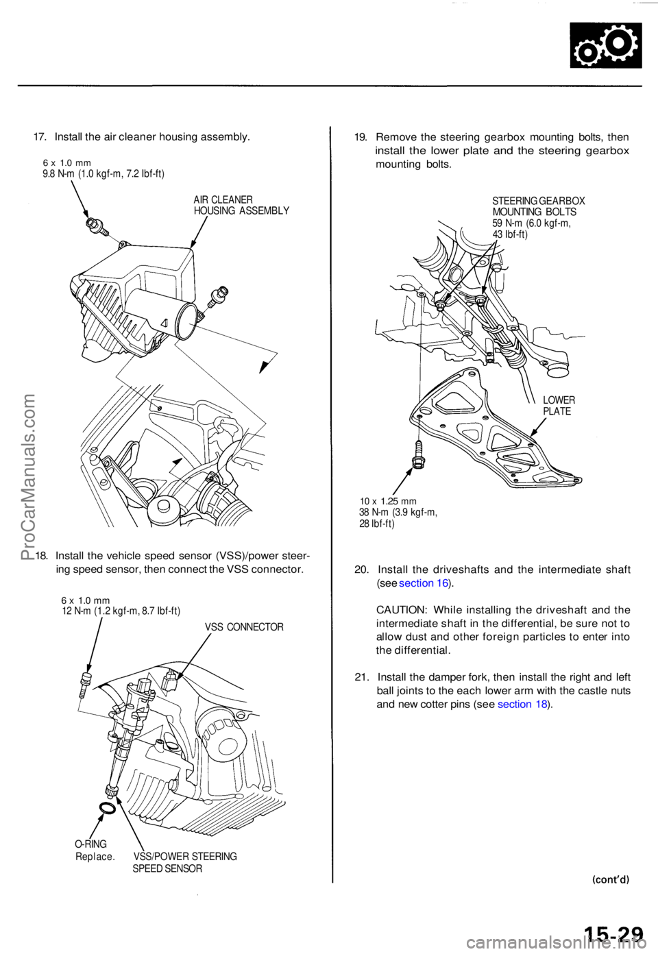
17. Instal l th e ai r cleane r housin g assembly .
6 x 1. 0 m m9.8 N- m (1. 0 kgf-m , 7. 2 Ibf-ft )
AIR CLEANE RHOUSING ASSEMBL Y
18. Instal l th e vehicl e spee d senso r (VSS)/powe r steer -
in g spee d sensor , the n connec t th e VS S connector .
6 x 1. 0 m m12 N- m (1. 2 kgf-m , 8. 7 Ibf-ft )
VSS CONNECTO R
O-RIN G
Replace . VSS/POWE R STEERIN G
SPEE D SENSO R
19. Remov e th e steerin g gearbo x mountin g bolts , the n
instal l th e lowe r plat e an d th e steerin g gearbo x
mounting bolts .
STEERIN G GEARBO XMOUNTING BOLT S59 N- m (6. 0 kgf-m ,
4 3 Ibf-ft )
10 x 1.2 5 mm38 N- m (3. 9 kgf-m ,
2 8 Ibf-ft )
20. Instal l th e driveshaft s an d th e intermediat e shaf t
(se e sectio n 16 ).
CAUTION : Whil e installin g th e driveshaf t an d th e
intermediat e shaf t i n th e differential , b e sur e no t t o
allo w dus t an d othe r foreig n particle s t o ente r int o
th e differential .
21 . Instal l th e dampe r fork , the n instal l th e righ t an d lef t
bal l joint s t o th e eac h lowe r ar m wit h th e castl e nut s
an d ne w cotte r pin s (se e sectio n 18 ).
LOWE RPLATE
ProCarManuals.com
Page 942 of 1954
Differential Assembl y
Installatio n (cont'd )
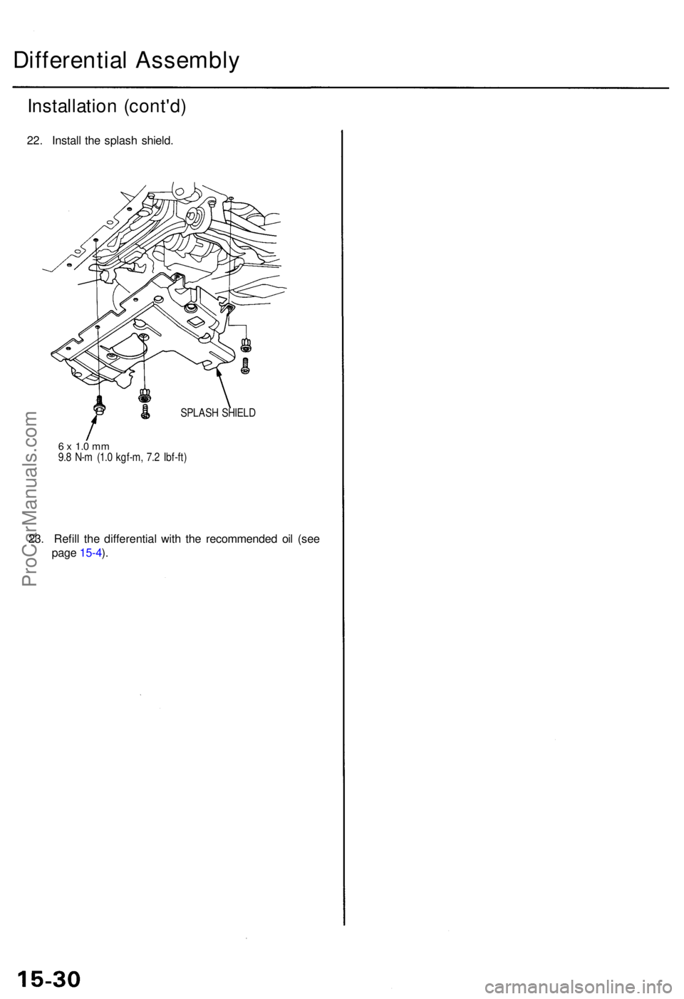
22. Instal l th e splas h shield .
SPLAS H SHIEL D
6 x 1. 0 m m9.8 N- m (1. 0 kgf-m , 7. 2 Ibf-ft )
23. Refil l th e differentia l wit h th e recommende d oi l (se e
pag e 15-4 ).
ProCarManuals.com
Page 943 of 1954
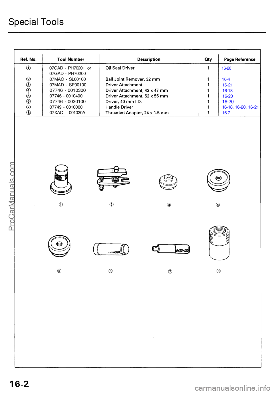
07GAD - PH7020 1 o r
07GA D - PH7020 0
07MA C - SL0010 0
07MA D - SP0010 0
07746 - 001030 0
07746 - 001040 0
07746 - 003010 0
07749 - 001000 0
07XA C - 001020 A
16-20
16-4
16-2 1
16-1 8
16-2 0
16-2 0
16-18 , 16-20 , 16-2 1
16-7
Specia l Tool s
ProCarManuals.com
Page 944 of 1954
Driveshafts
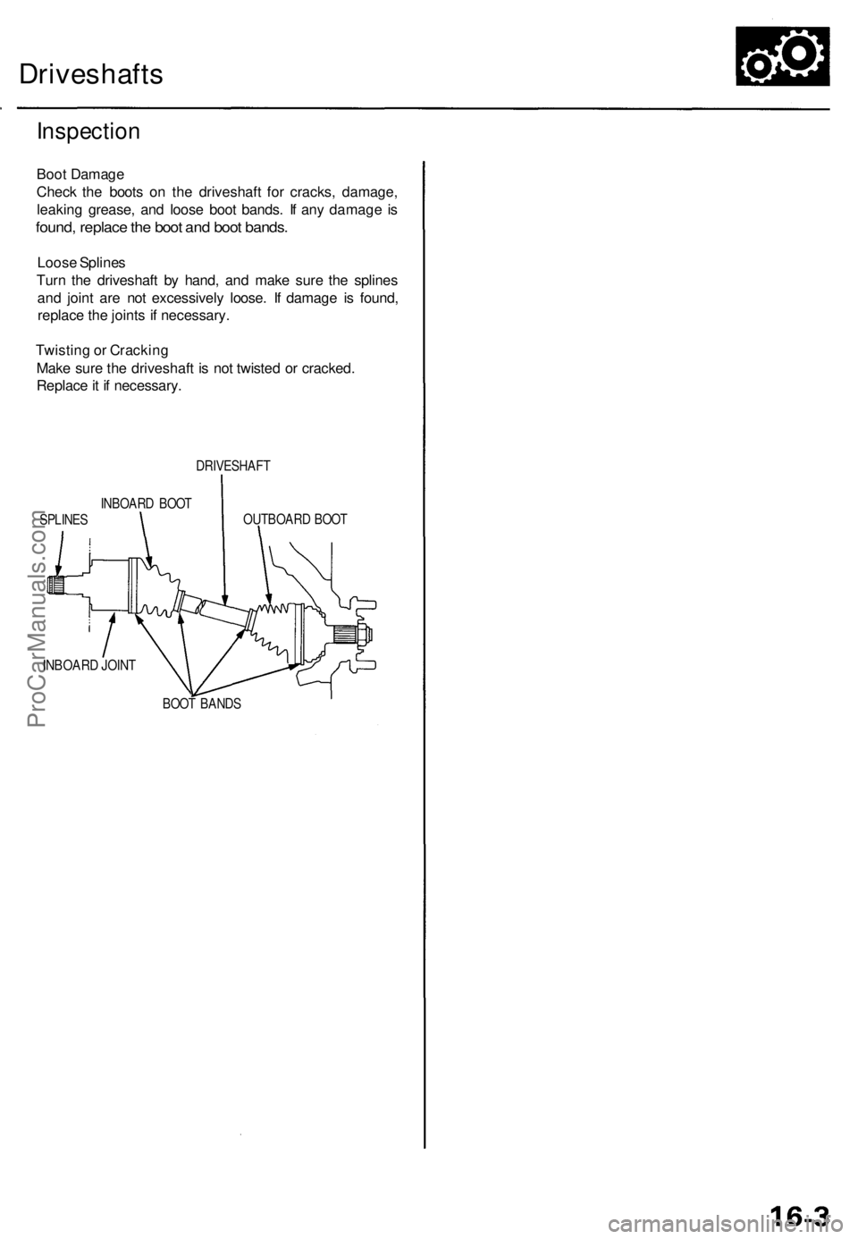
Inspection
Boot Damage
Check the boots on the driveshaft for cracks, damage,
leaking grease, and loose boot bands. If any damage is
found, replace the boot and boot bands.
Loose Splines
Turn the driveshaft by hand, and make sure the splines
and joint are not excessively loose. If damage is found,
replace the joints if necessary.
Twisting or Cracking
Make sure the driveshaft is not twisted or cracked.
Replace it if necessary.
DRIVESHAFT
INBOARD BOOT
SPLINES
OUTBOARD BOOT
INBOARD JOINT
BOOT BANDSProCarManuals.com
Page 945 of 1954
Driveshafts
Removal
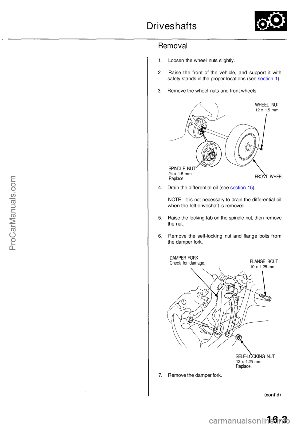
1. Loose n th e whee l nut s slightly .
2 . Rais e th e fron t o f th e vehicle , an d suppor t i t wit h
safet y stand s in th e prope r location s (se e sectio n 1 ).
3 . Remov e th e whee l nut s an d fron t wheels .
WHEEL NU T12 x 1. 5 m m
SPINDL E NU T24 x 1. 5 m mReplace . FRON
T WHEE L
4. Drai n th e differentia l oi l (se e sectio n 15 ).
NOTE : I t i s no t necessar y t o drai n th e differentia l oi l
whe n th e lef t driveshaf t i s removed .
5. Rais e th e lockin g ta b o n th e spindl e nut , the n remov e
the nut .
6. Remov e th e self-lockin g nu t an d flang e bolt s fro m
th e dampe r fork .
DAMPE R FOR K
Chec k fo r damage . FLANG
E BOL T
10 x 1.2 5 mm
7. Remov e th e dampe r fork .
SELF-LOCKIN G NU T12 x 1.2 5 mmReplace .
ProCarManuals.com
Page 946 of 1954
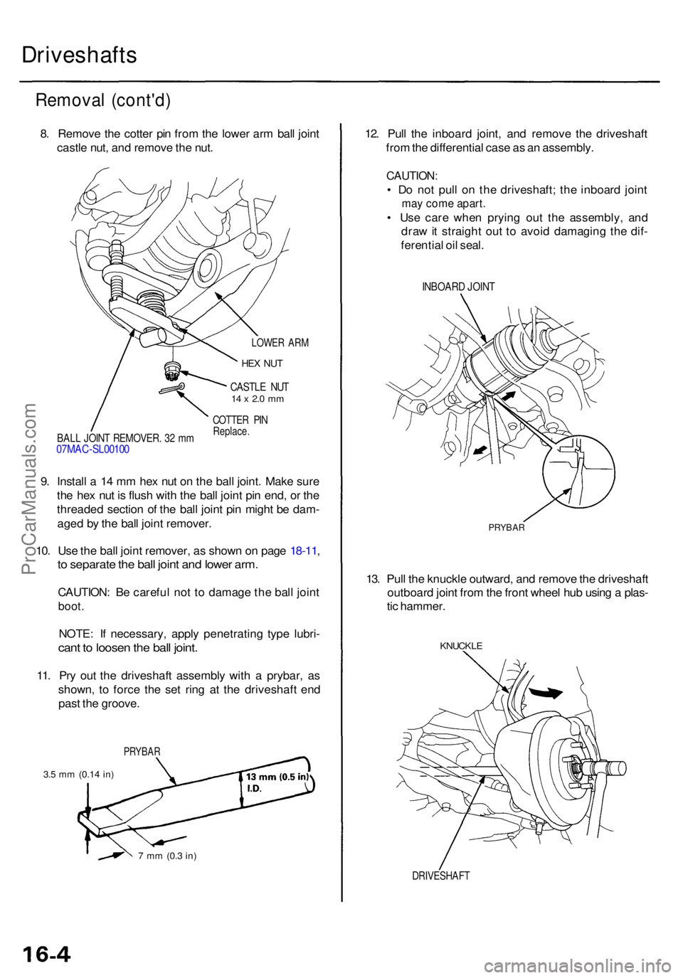
DRIVESHAFT
KNUCKLE
13. Pul l th e knuckl e outward , an d remov e th e driveshaf t
outboar d join t fro m th e fron t whee l hu b usin g a plas -
ti c hammer .
12
. Pul l th e inboar d joint , an d remov e th e driveshaf t
fro m th e differentia l cas e a s a n assembly .
CAUTION:
• D o no t pul l o n th e driveshaft ; th e inboar d join t
may com e apart .
• Us e car e whe n pryin g ou t th e assembly , an d
dra w it straigh t ou t t o avoi d damagin g th e dif -
ferentia l oi l seal .
INBOAR D JOIN T
Remova l (cont'd )
8. Remov e th e cotte r pi n fro m th e lowe r ar m bal l join t
castl e nut , an d remov e th e nut .
Driveshaft s
LOWER AR M
HEX NU T
CASTL E NU T14 x 2. 0 m m
COTTE R PI NReplace .BALL JOIN T REMOVER . 3 2 m m07MA C-SL0010 0
9. Instal l a 14 m m he x nu t o n th e bal l joint . Mak e sur e
th e he x nu t i s flus h wit h th e bal l join t pi n end , o r th e
threade d sectio n o f th e bal l join t pi n migh t b e dam -
age d b y th e bal l join t remover .
10 . Us e th e bal l join t remover , a s show n o n pag e 18-11 ,
to separat e th e bal l join t an d lowe r arm .
CAUTION : B e carefu l no t t o damag e th e bal l join t
boot .
NOTE : I f necessary , appl y penetratin g typ e lubri -
cant t o loose n th e bal l joint .
11. Pr y ou t th e driveshaf t assembl y wit h a prybar , a s
shown , t o forc e th e se t rin g a t th e driveshaf t en d
pas t th e groove .
PRYBA R
3.5 m m (0.1 4 in)
7 m m (0. 3 in)
PRYBA R
ProCarManuals.com
Page 947 of 1954
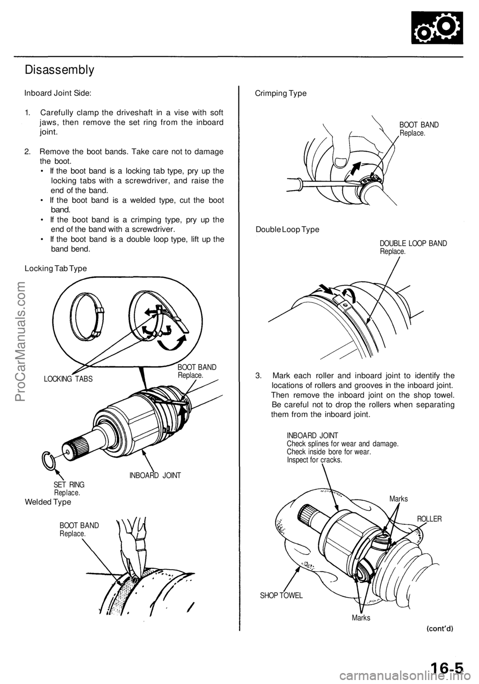
SET RIN GReplace .
Welded Typ e
BOO T BAN DReplace .
INBOARD JOIN T
SHOP TOWE L
Marks
Crimpin g Typ e
BOO T BAN DReplace .
Double Loo p Typ e
DOUBL E LOO P BAN DReplace .
3. Mar k eac h rolle r an d inboar d join t t o identif y th e
location s o f roller s an d groove s in th e inboar d joint .
The n remov e th e inboar d join t o n th e sho p towel .
B e carefu l no t t o dro p th e roller s whe n separatin g
the m fro m th e inboar d joint .
INBOAR D JOIN T
Chec k spline s fo r wea r an d damage .
Chec k insid e bor e fo r wear .
Inspec t fo r cracks .
ROLLER
Marks
Disassembl y
Inboard Join t Side :
1 . Carefull y clam p th e driveshaf t i n a vis e wit h sof t
jaws , the n remov e th e se t rin g fro m th e inboar d
joint.
2. Remov e th e boo t bands . Tak e car e no t t o damag e
th e boot .
• I f th e boo t ban d i s a lockin g ta b type , pr y u p th e
lockin g tab s wit h a screwdriver , an d rais e th e
en d o f th e band .
• I f th e boo t ban d i s a welde d type , cu t th e boo t
band.
• I f th e boo t ban d i s a crimpin g type , pr y u p th e
en d o f th e ban d wit h a screwdriver .
• I f th e boo t ban d i s a doubl e loo p type , lif t u p th e
ban d bend .
Lockin g Ta b Typ e
LOCKIN G TAB S BOO
T BAN D
Replace .
ProCarManuals.com
Page 948 of 1954
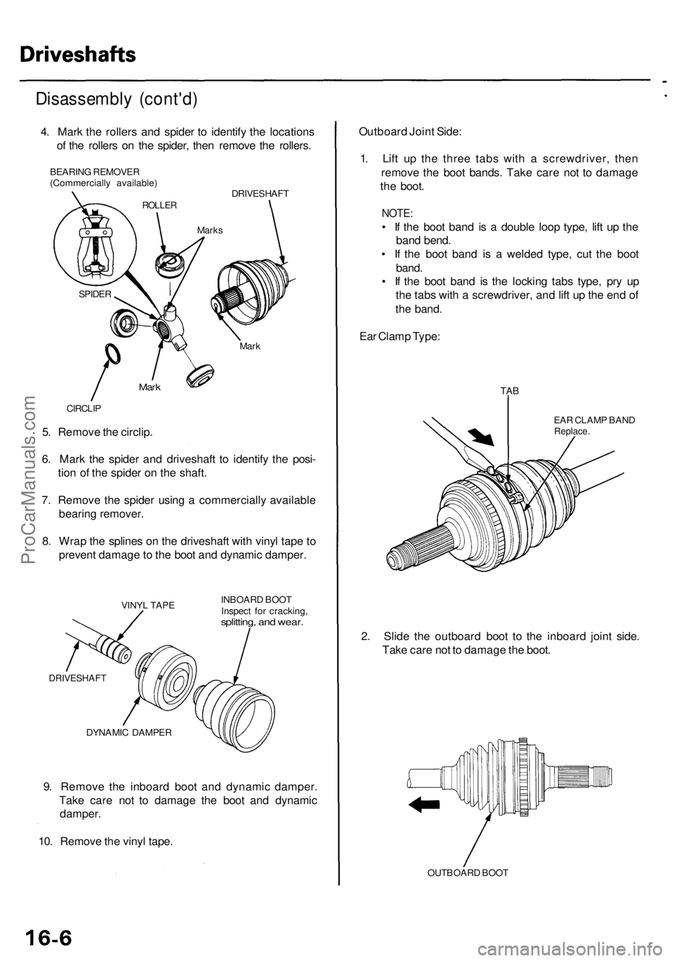
9. Remov e th e inboar d boo t an d dynami c damper .
Tak e car e no t t o damag e th e boo t an d dynami c
damper .
10 . Remov e th e viny l tape .
DYNAMI C DAMPE R INBOAR
D BOO T
Inspec t fo r cracking ,
splitting, an d wear .
VINY L TAP E
DRIVESHAF T
5. Remov e th e circlip .
6 . Mar k th e spide r an d driveshaf t t o identif y th e posi -
tio n o f th e spide r o n th e shaft .
7 . Remov e th e spide r usin g a commerciall y availabl e
bearin g remover .
8 . Wra p th e spline s o n th e driveshaf t wit h viny l tap e t o
preven t damag e to th e boo t an d dynami c damper .
CIRCLIP
Mark
Mar k
SPIDE R
Disassembl y (cont'd )
4. Mar k th e roller s an d spide r t o identif y th e location s
o f th e roller s o n th e spider , the n remov e th e rollers .
BEARIN G REMOVE R
(Commerciall y available )
ROLLER
Marks
DRIVESHAF T
Outboard Join t Side :
1 . Lif t u p th e thre e tab s wit h a screwdriver , the n
remov e th e boo t bands . Tak e car e no t t o damag e
th e boot .
NOTE :
• I f th e boo t ban d i s a doubl e loo p type , lif t u p th e
ban d bend .
• I f th e boo t ban d i s a welde d type , cu t th e boo t
band .
• I f th e boo t ban d i s th e lockin g tab s type , pr y u p
th e tab s wit h a screwdriver , an d lif t u p th e en d o f
th e band .
Ea r Clam p Type :
EAR CLAM P BAN DReplace .
TAB
2. Slid e th e outboar d boo t t o th e inboar d join t side .
Tak e car e no t t o damag e th e boot .
OUTBOAR D BOO T
ProCarManuals.com
Page 949 of 1954
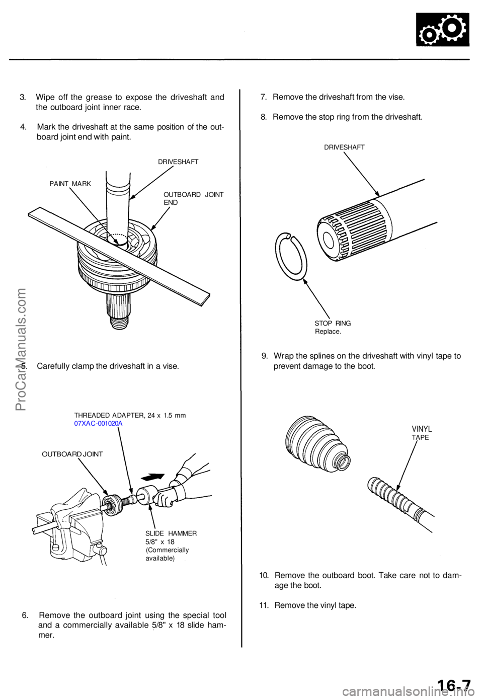
6. Remov e th e outboar d join t usin g th e specia l too l
an d a commerciall y availabl e 5/8 " x 1 8 slid e ham -
mer.
SLID E HAMME R5/8" x 1 8(Commerciall y
available )
OUTBOAR D JOIN T
THREADE D ADAPTER , 2 4 x 1. 5 m m
07XA C-001020 A
10. Remov e th e outboar d boot . Tak e car e no t t o dam -
ag e th e boot .
11 . Remov e th e viny l tape .
7
. Remov e th e driveshaf t fro m th e vise .
8 . Remov e th e sto p rin g fro m th e driveshaft .
DRIVESHAF T
STO P RIN G
Replace .
9. Wra p th e spline s o n th e driveshaf t wit h viny l tap e t o
preven t damag e to th e boot .
VINY LTAPE
5. Carefull y clam p th e driveshaf t i n a vise .
OUTBOAR D JOIN TEND
PAIN T MAR K DRIVESHAF
T
3. Wip e of f th e greas e t o expos e th e driveshaf t an d
th e outboar d join t inne r race .
4 . Mar k th e driveshaf t a t th e sam e positio n o f th e out -
boar d join t en d wit h paint .
ProCarManuals.com
Page 950 of 1954
Driveshafts
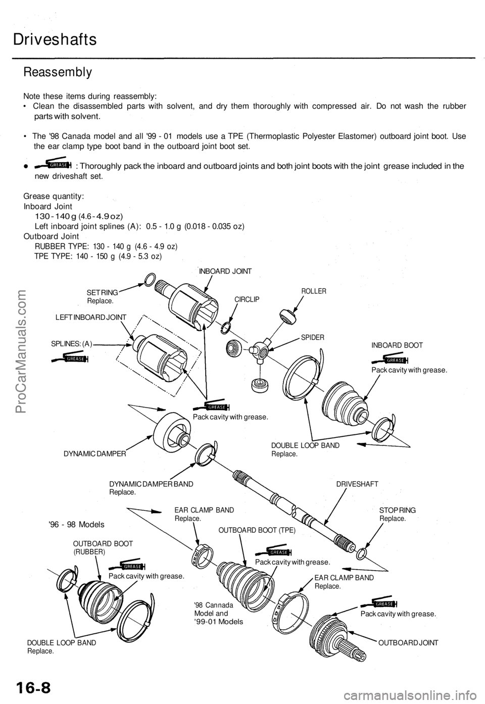
Reassembl y
Note thes e item s durin g reassembly :
• Clea n th e disassemble d part s wit h solvent , an d dr y the m thoroughl y wit h compresse d air . D o no t was h th e rubbe r
parts wit h solvent .
• Th e '9 8 Canad a mode l an d al l '9 9 - 0 1 model s us e a TP E (Thermoplasti c Polyeste r Elastomer ) outboar d join t boot . Us e
th e ea r clam p typ e boo t ban d i n th e outboar d join t boo t set .
ne w driveshaf t set .
: Thoroughl y pac k th e inboar d an d outboar d joint s an d bot h join t boot s wit h th e join t greas e include d in th e
Greas e quantity :
Inboar d Join t
130 - 14 0 g (4. 6 - 4. 9 oz )
Lef t inboar d join t spline s (A) : 0. 5 - 1. 0 g (0.01 8 - 0.03 5 oz )
Outboar d Join t
RUBBE R TYPE : 13 0 - 14 0 g (4. 6 - 4. 9 oz )
TPE TYPE : 14 0 - 15 0 g (4. 9 - 5. 3 oz )
SET RIN GReplace .
LEFT INBOAR D JOIN T
SPLINES : (A )
INBOAR D JOIN T
CIRCLI PROLLE R
SPIDERINBOAR D BOO T
Pack cavit y wit h grease .
STO P RIN G
Replace .
DRIVESHAF T
DOUBLE LOO P BAN DReplace .
Pack cavit y wit h grease .
Pack cavit y wit h grease .
OUTBOAR D JOIN T
EAR CLAM P BAN DReplace .
'98 Cannad aModel an d'99-0 1 Model s
DYNAMI C DAMPE R
DYNAMI C DAMPE R BAN D
Replace .
EAR CLAM P BAN DReplace .
OUTBOAR D BOO T (TPE )
Pack cavit y wit h grease .
Pac k cavit y wit h grease .
'96 - 9 8 Model s
OUTBOAR D BOO T(RUBBER )
DOUBLE LOO P BAN DReplace .
ProCarManuals.com