ACURA TL 1995 Service Repair Manual
Manufacturer: ACURA, Model Year: 1995, Model line: TL, Model: ACURA TL 1995Pages: 1771, PDF Size: 62.49 MB
Page 1131 of 1771
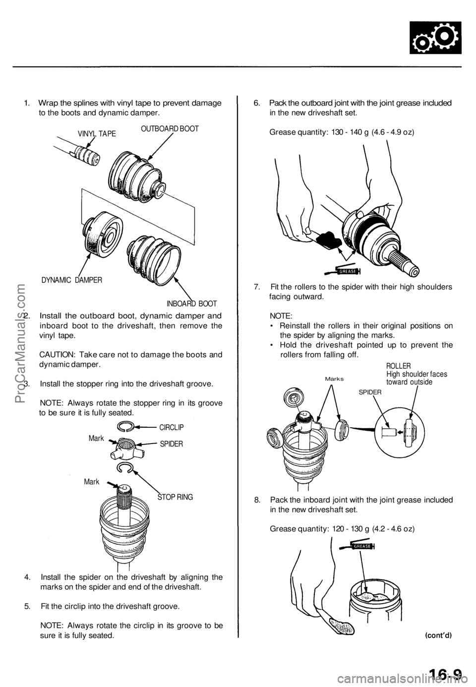
1. Wra p th e spline s wit h viny l tap e to preven t damag e
to th e boot s an d dynami c damper .
VINYL TAP E OUTBOAR
D BOO T
DYNAMI C DAMPE R
INBOARD BOO T
2. Instal l th e outboar d boot , dynami c dampe r an d
inboar d boo t t o th e driveshaft , the n remov e th e
viny l tape .
CAUTION : Tak e car e no t t o damag e th e boot s an d
dynami c damper .
3 . Instal l th e stoppe r rin g int o th e driveshaf t groove .
NOTE : Alway s rotat e th e stoppe r rin g i n it s groov e
t o b e sur e it i s full y seated .
Mark
Mar k
STOP RIN G
4. Instal l th e spide r o n th e driveshaf t b y alignin g th e
mark s o n th e spide r an d en d o f th e driveshaft .
5 . Fi t th e circli p int o th e driveshaf t groove .
NOTE : Alway s rotat e th e circli p in it s groov e t o b e
sur e it i s full y seated .
6. Pac k th e outboar d join t wit h th e join t greas e include d
in th e ne w driveshaf t set .
Greas e quantity : 13 0 - 14 0 g (4. 6 - 4. 9 oz )
7 . Fi t th e roller s t o th e spide r wit h thei r hig h shoulder s
facin g outward .
NOTE:
• Reinstal l th e roller s i n thei r origina l position s o n
th e spide r b y alignin g th e marks .
• Hol d th e driveshaf t pointe d u p t o preven t th e
roller s fro m fallin g off .
ROLLE RHigh shoulde r face sMark s towar d outsid e
SPIDER
8. Pac k th e inboar d join t wit h th e join t greas e include d
i n th e ne w driveshaf t set .
Greas e quantity : 12 0 - 13 0 g (4. 2 - 4. 6 oz )
CIRCLI P
SPIDER
ProCarManuals.com
Page 1132 of 1771

Driveshaft
Reassembl y (cont'd )
9. Fi t th e inboar d join t ont o th e driveshaft .
NOTE:
• Reinstal l th e inboar d join t ont o th e driveshaf t b y
alignin g th e mark s o n th e inboar d join t an d th e
rollers .
• Hol d th e driveshaf t s o th e inboar d join t point s u p
t o preven t i t fro m fallin g off .
INBOAR DJOINT
10. Adjus t th e lengt h of the driveshaft s t o th e figur e
below , the n adjus t th e boot s t o halfwa y betwee n
full compressio n an d ful l extension .
NOTE: Th e end s o f boot s sea t i n th e groov e o f th e
driveshaf t an d joint .
Left: 49 6 - 50 1 m m (19. 5 - 19. 7 in )
Right : 50 3 - 50 8 m m (19. 8 - 20. 0 in )
11. Positio n th e dynami c dampe r a s show n below .
45 2 mm (1. 8 0. 1 in )
DYNAMI C DAMPE R
(Fo r righ t driveshaft )
DYNAMI C DAMPE R BAN D
12. Se t th e doubl e loo p ban d ont o th e boo t an d dynami c
damper wit h th e ban d en d towar d t o fron t o f th e
vehicle .
Front DOUBL
E LOO P BAN D
BOO T
NOTE : Refe r t o page 16-3a of the '96-9 8 Acura 3.2TL Servic e Manual supplement forfor the differences on this page for the 3.2TL.
ProCarManuals.com
Page 1133 of 1771
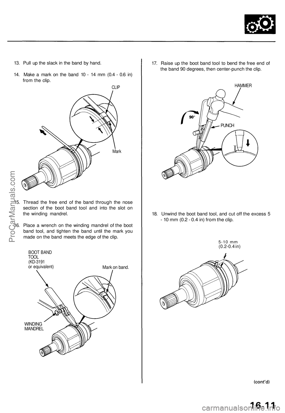
13. Pul l u p th e slac k in th e ban d b y hand .
14 . Mak e a mar k o n th e ban d 1 0 - 1 4 m m (0. 4 - 0. 6 in )
fro m th e clip .
CLIP
Mar k
15. Threa d th e fre e en d o f th e ban d throug h th e nos e
sectio n o f th e boo t ban d too l an d int o th e slo t o n
th e windin g mandrel .
16 . Plac e a wrenc h o n th e windin g mandre l o f th e boo t
ban d tool , an d tighte n th e ban d unti l th e mar k yo u
mad e o n th e ban d meet s th e edg e o f th e clip .
BOO T BAN D
TOO L
(KD-319 1
or equivalent )
Mark o n band .
WINDIN G
MANDRE L
17. Rais e u p th e boo t ban d too l t o ben d th e fre e en d o f
th e ban d 9 0 degrees , the n center-punc h th e clip .
HAMME R
18. Unwin d th e boo t ban d tool , an d cu t of f th e exces s 5
- 1 0 m m (0. 2 - 0. 4 in ) fro m th e clip .
5-1 0 mm(0.2-0. 4 in )
PUNC H
ProCarManuals.com
Page 1134 of 1771
Driveshaft
Reassembl y (cont'd )
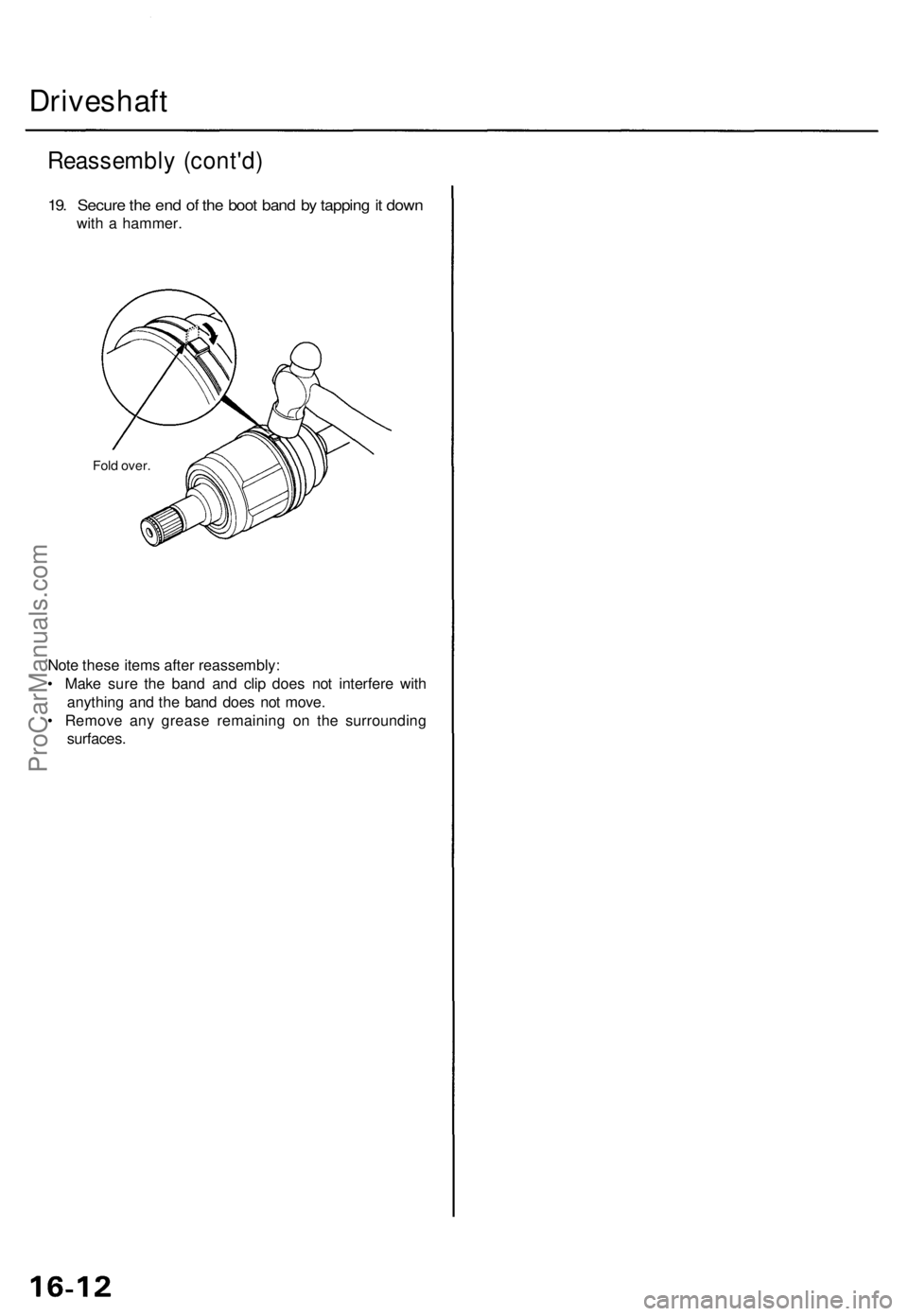
19. Secur e th e en d o f th e boo t ban d b y tappin g it dow n
with a hammer .
Fold over .
Note thes e item s afte r reassembly :
• Mak e sur e th e ban d an d cli p doe s no t interfer e wit h
anythin g an d th e ban d doe s no t move .
• Remov e an y greas e remainin g o n th e surroundin g
surfaces .
ProCarManuals.com
Page 1135 of 1771
Driveshaft
Installation
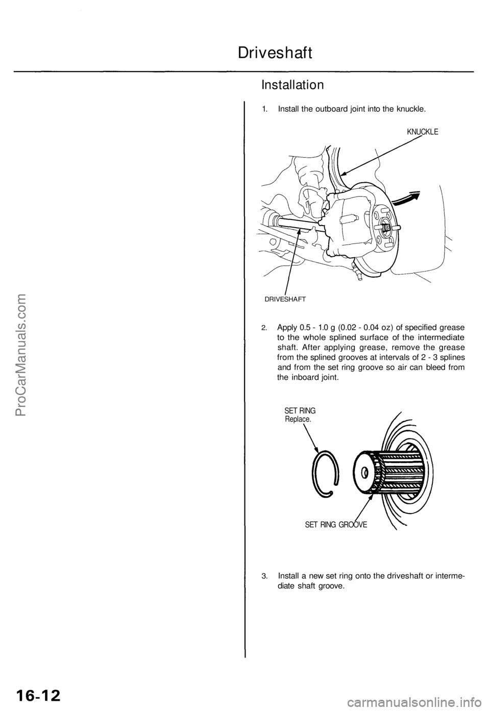
1. Instal l th e outboar d join t int o th e knuckle .
KNUCKL E
DRIVESHAF T
2.Appl y 0. 5 - 1. 0 g (0.0 2 - 0.0 4 oz ) o f specifie d greas e
to th e whol e spline d surfac e o f th e intermediat e
shaft. Afte r applyin g grease , remov e th e greas e
fro m th e spline d groove s a t interval s o f 2 - 3 spline s
an d fro m th e se t rin g groov e s o ai r ca n blee d fro m
th e inboar d joint .
SET RIN GReplace .
3.
SE T RIN G GROOV E
Install a ne w se t rin g ont o th e driveshaf t o r interme -
diat e shaf t groove .
ProCarManuals.com
Page 1136 of 1771

4. Instal l th e inboar d en d o f th e driveshaf t int o th e dif -
ferentia l o r th e intermediat e shaft .
SET RIN GReplace .Make sur e th e lef t driveshaf t lock s in th e differen -
tia l sid e gea r groove , an d th e inboar d join t sub-axl e
bottom s i n th e differential .
Lef t Driveshaf t
SE T RIN G GROOV E SE
T RIN G
Replace .
Right Driveshaf t
Inser t th e righ t driveshaf t inboar d join t sub-axl e int o
the intermediat e shaf t unti l th e intermediat e shaf tset rin g lock s in th e groov e in th e righ t driveshaft .
5. Instal l th e knuckl e o n th e lowe r arm , the n tighte n
the castl e nu t an d instal l a ne w cotte r pin .
FLANG E BOL T10 x 1.2 5 mm43 N- m (4. 4 kgf-m , 3 2 Ibf-ft )
SELF-LOCKIN G NU T
12 x 1.2 5 mm64 N- m (6. 5 kgf-m , 4 7 Ibf-ft )Replace .
CASTL E NU T
14 x 2. 0 m m49-5 9 N- m (5. 0 - 6. 0 kgf-m ,
36-4 3 Ibf-ft )
6. Instal l th e dampe r for k ove r th e driveshaf t an d ont o
th e lowe r arm . Instal l th e dampe r i n th e dampe r
fork s o th e alignin g ta b i s aligne d wit h th e slo t i n
th e dampe r for k (se e sectio n 18 ).
Loosel y instal l th e flang e bolt s an d th e ne w self -
lockin g nut .
NOTE : Th e bolt s an d nu t shoul d b e tightene d wit h
the vehicle' s weigh t o n th e damper .
Install a ne w spindl e nut , the n tighte n th e nut .
7.
8.
FRON T WHEE L
WHEE L NU T
SPINDL E NU T24 x 1. 5 m mReplace .
9. Instal l th e fron t whee l wit h th e whee l nuts .
NOTE : Befor e installin g th e wheel , clea n th e matin g
surface s o f th e brak e dis c an d th e wheel .
10 . Tighte n th e flang e bolt s an d th e ne w self-lockin g
nu t wit h th e vehicle' s weigh t o n th e damper .
11. Refil l th e transmissio n wit h recommende d flui d (se e
sectio n 14 ).
12 . Chec k th e fron t whee l alignmen t an d adjus t i f nec -
essar y (se e sectio n 18 ).
COTTE R PI N'Replace .On reassembly , ben d th ecotte r pi n a s shown .
SET RIN G GROOV ESIDE GEA R
ProCarManuals.com
Page 1137 of 1771

Intermediate Shaf t
Removal/Installatio n
1. Drai n th e automati c transmissio n flui d (se e
section 14 ).
2 . Remov e th e righ t driveshaf t assembl y (se e pag e 16-3 ).
3 . Remov e th e thre e flang e bolts .
FLANG E BOL T8 x 1.2 5 mm
4. Remov e th e intermediat e shaf t assembl y fro m th e
oil pan .
INTERMEDIAT E SHAF T
5. Instal l th e intermediat e shaf t i n th e revers e orde r o f
removal .
CAUTION : Whe n installing , mak e sur e th e O-rin g i s
i n plac e an d no t pinched .
NOTE : Appl y sealan t t o th e bol t threads , an d tighte n
th e bolt s t o th e specifie d torque .
22 N- m (2. 2 kgf-m , 1 6 Ibf-ft )
ProCarManuals.com
Page 1138 of 1771
Intermediate Shaf t
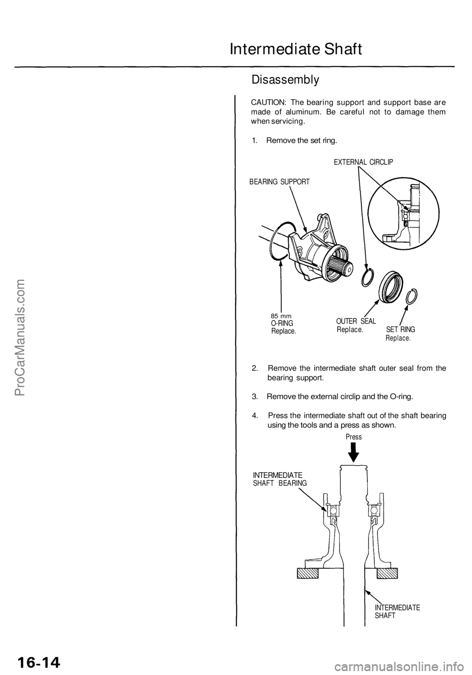
Disassembl y
CAUTION: Th e bearin g suppor t an d suppor t bas e ar e
mad e o f aluminum . B e carefu l no t t o damag e the m
whe n servicing .
1. Remov e th e se t ring .
EXTERNA L CIRCLI P
BEARIN G SUPPOR T
85 m mO-RIN G
Replace . OUTE
R SEA L
Replace . SE T RIN G
Replace .
2. Remov e th e intermediat e shaf t oute r sea l fro m th e
bearin g support .
3. Remov e th e externa l circli p an d th e O-ring .
4. Pres s th e intermediat e shaf t ou t o f th e shaf t bearin g
using th e tool s an d a pres s a s shown .
Press
INTERMEDIAT ESHAFT BEARIN G
INTERMEDIATE
SHAF T
ProCarManuals.com
Page 1139 of 1771
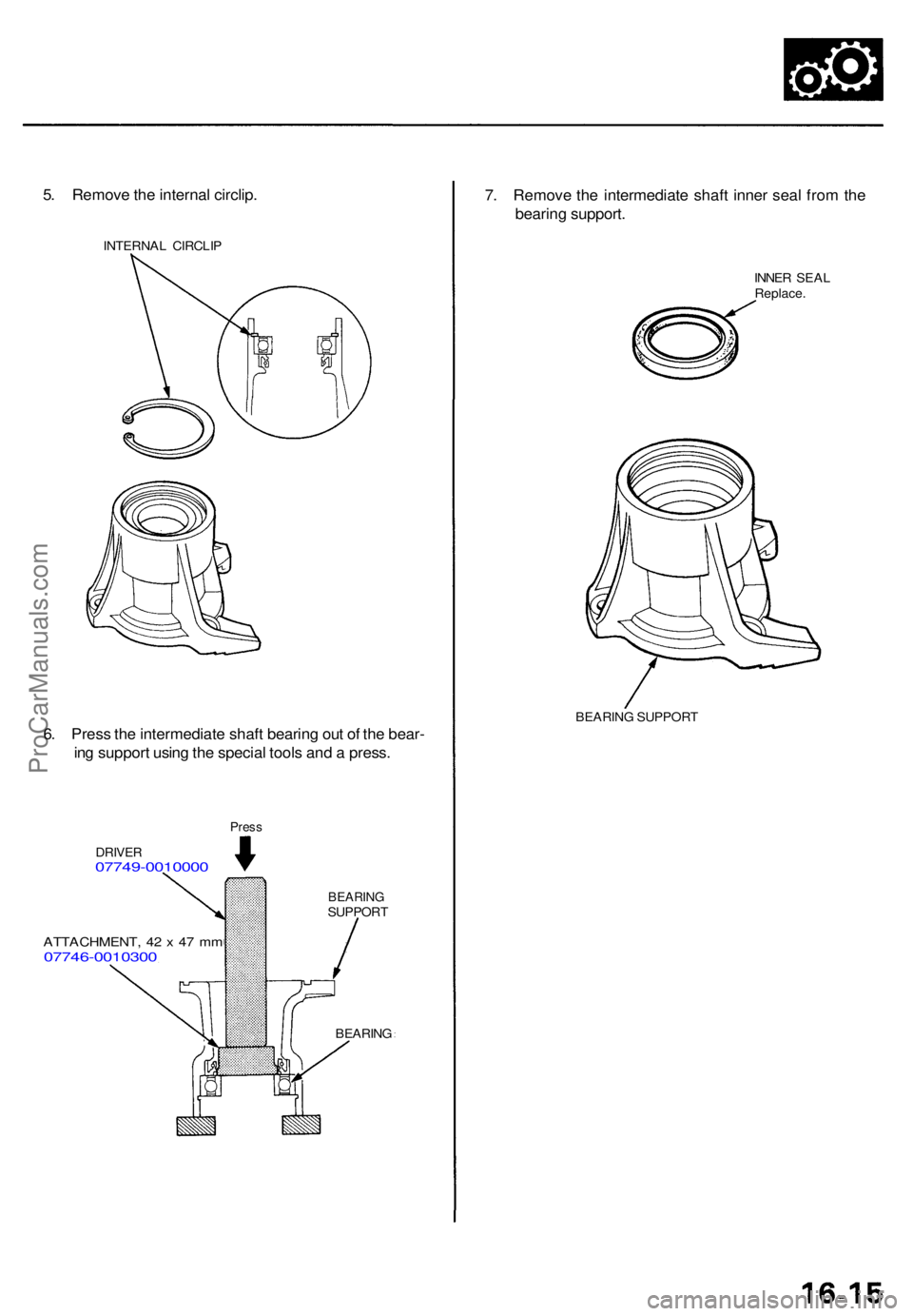
5. Remov e th e interna l circlip .
INTERNA L CIRCLI P
6. Pres s th e intermediat e shaf t bearin g ou t o f th e bear -
in g suppor t usin g th e specia l tool s an d a press .
Press
DRIVE R07749-001000 0
ATTACHMENT , 4 2 x 47 m m07746-001030 0
BEARINGSUPPOR T
BEARING
7. Remov e th e intermediat e shaf t inne r sea l fro m th e
bearin g support .
INNER SEA L
Replace .
BEARIN G SUPPOR T
ProCarManuals.com
Page 1140 of 1771

Intermediate Shaf t
Reassembl y
CAUTION:
• Th e bearin g suppor t i s mad e o f aluminum . B e carefu l no t t o damag e it whe n servicing .
• D o no t damag e th e li p o n inne r an d oute r seal s durin g installation .
INTERMEDIAT E SHAF T
Chec k fo r damage .
BEARING SUPPOR T
Chec k fo r damage .
INNER SEA LReplace .
85 m mO-RIN GReplac e
INTERMEDIAT E SHAF TBEARIN GReplace.
INTERNA LCIRCLIPOUTER SEA LReplace .
Pack th e interio r an d li p o f th e
oute r seal .
EXTERNA LCIRCLIP
ProCarManuals.com