ACURA TL 1995 Service Repair Manual
Manufacturer: ACURA, Model Year: 1995, Model line: TL, Model: ACURA TL 1995Pages: 1771, PDF Size: 62.49 MB
Page 1191 of 1771
Steering Gearbo x
Remova l
NOTE: Us e solven t an d a brus h t o was h of f an y oi l an d
dirt fro m th e valv e bod y unit , it s lines , an d th e en d o f
the gearbox . Blo w dr y wit h compresse d air .
1. Drai n th e powe r steerin g flui d a s describe d o n pag e
17-24 .
2. Rais e th e fron t o f vehicle , an d suppor t i t o n safet y
stands in th e prope r locations , (se e sectio n 1 )
3 . Remov e th e fron t wheels .
4 . Remov e th e driver' s airba g assembl y an d steerin g
whee l (se e pag e 17-27 ).
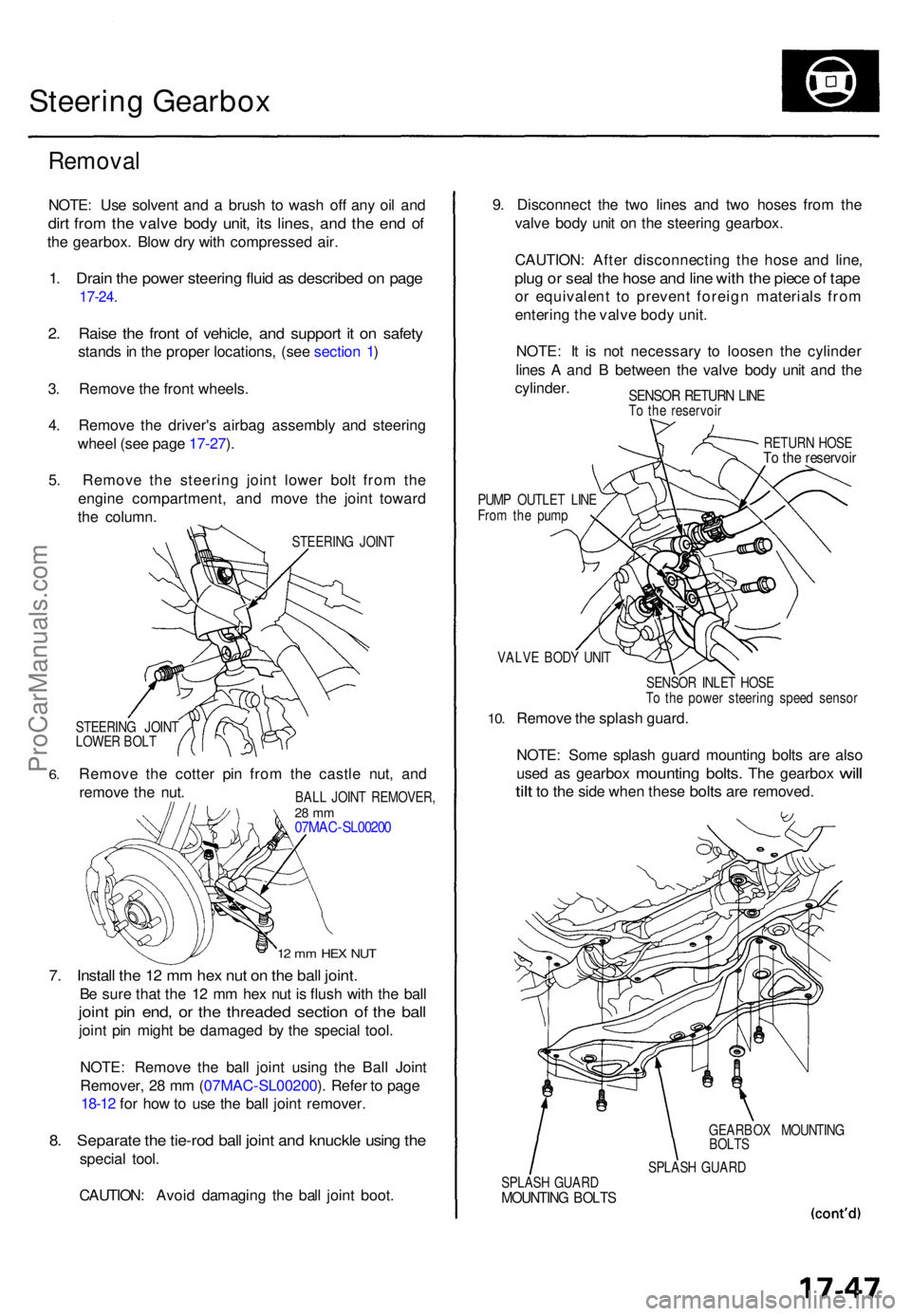
5 . Remov e th e steerin g join t lowe r bol t fro m th e
engin e compartment , an d mov e th e join t towar d
th e column .
STEERIN G JOIN T
6.
STEERIN G JOIN T
LOWE R BOL T
Remov e th e cotte r pi n fro m th e castl e nut , an d
remov e th e nut .
12 m m HE X NU T
7. Instal l th e 1 2 m m he x nu t o n th e bal l joint .
Be sur e tha t th e 1 2 m m he x nu t i s flus h wit h th e bal l
joint pi n end , o r th e threade d sectio n o f th e bal l
joint pi n migh t b e damage d b y th e specia l tool .
NOTE : Remov e th e bal l join t usin g th e Bal l Join t
Remover , 2 8 m m (07MA C-SL00200 ). Refe r t o pag e
18-12 for ho w to us e th e bal l join t remover .
8. Separat e th e tie-ro d bal l join t an d knuckl e usin g th e
specia l tool .
CAUTION : Avoi d damagin g th e bal l join t boot . 9
. Disconnec t th e tw o line s an d tw o hose s fro m th e
valv e bod y uni t o n th e steerin g gearbox .
CAUTION : Afte r disconnectin g th e hos e an d line ,
plug o r sea l th e hos e an d lin e wit h th e piec e o f tap e
or equivalen t t o preven t foreig n material s fro m
enterin g th e valv e bod y unit .
NOTE : I t i s no t necessar y t o loose n th e cylinde r
line s A an d B betwee n th e valv e bod y uni t an d th e
cylinder .
SENSOR RETUR N LIN ETo th e reservoi r
RETURN HOS E
To th e reservoi r
PUMP OUTLE T LIN E
Fro m th e pum p
VALV E BOD Y UNI T
10.
SENSO R INLE T HOS E
T o th e powe r steerin g spee d senso r
Remove th e splas h guard .
NOTE : Som e splas h guar d mountin g bolt s ar e als o
use d
as gearbo x mountin g bolts. The gearbo x will
til t
to th e sid e whe n thes e bolts are removed .
GEARBO X MOUNTIN G
BOLT S
SPLAS H GUAR D
SPLAS H GUAR D
MOUNTIN G BOLT S
BALL JOIN T REMOVER ,28 m m07MA C-SL0020 0
ProCarManuals.com
Page 1192 of 1771
Steering Gearbo x
Remova l (cont'd )
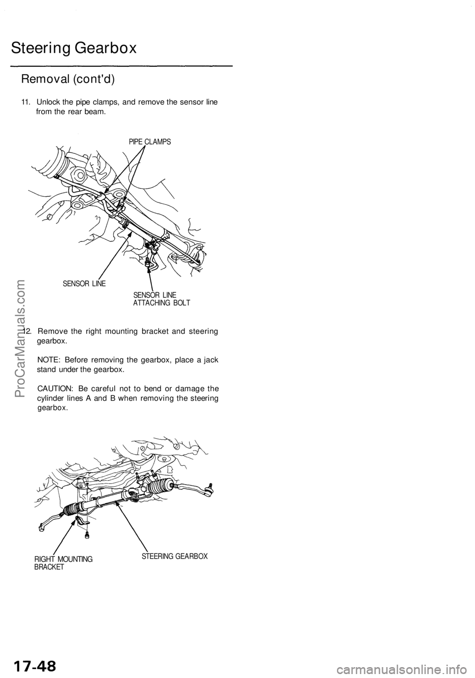
11. Unloc k th e pip e clamps , an d remov e th e senso r lin e
fro m th e rea r beam .
PIPE CLAMP S
SENSO R LIN E
SENSOR LIN E
ATTACHIN G BOL T
12. Remov e th e righ t mountin g bracke t an d steerin g
gearbox .
NOTE : Befor e removin g th e gearbox , plac e a jac k
stan d unde r th e gearbox .
CAUTION : B e carefu l no t t o ben d o r damag e th e
cylinde r line s A an d B whe n removin g th e steerin g
gearbox .
RIGHT MOUNTIN GBRACKET STEERIN
G GEARBO X
ProCarManuals.com
Page 1193 of 1771
Disassembly
Steering Rac k Disassembl y
NOTE:
• Befor e disassemblin g th e steerin g gearbox , was h i t
of f wit h solven t an d a brush .
• D o no t di p seal s an d O-ring s i n solvent .
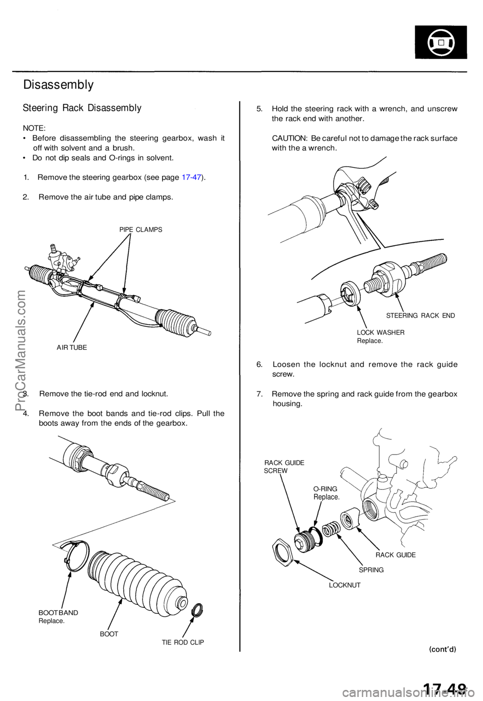
1 . Remov e th e steerin g gearbo x (se e pag e 17-47 ).
2 . Remov e th e ai r tub e an d pip e clamps .
PIPE CLAMP S
AIR TUB E
3. Remov e th e tie-ro d en d an d locknut .
4 . Remov e th e boo t band s an d tie-ro d clips . Pul l th e
boot s awa y fro m th e end s o f th e gearbox.
BOO T BAN DReplace .
BOOTTIE RO D CLI P
5. Hol d th e steerin g rac k wit h a wrench , an d unscre w
th e rac k en d wit h another .
CAUTION : B e carefu l no t t o damag e th e rac k surfac e
wit h th e a wrench .
STEERIN G RAC K EN D
LOC K WASHE RReplace.
6. Loose n th e locknu t an d remov e th e rac k guid e
screw .
7 . Remov e th e sprin g an d rac k guid e fro m th e gearbo x
housing .
RACK GUID ESCRE W
RACK GUID E
SPRIN G
LOCKNU T
O-RINGReplace .
ProCarManuals.com
Page 1194 of 1771
Steering Gearbo x
Disassembl y (cont'd )
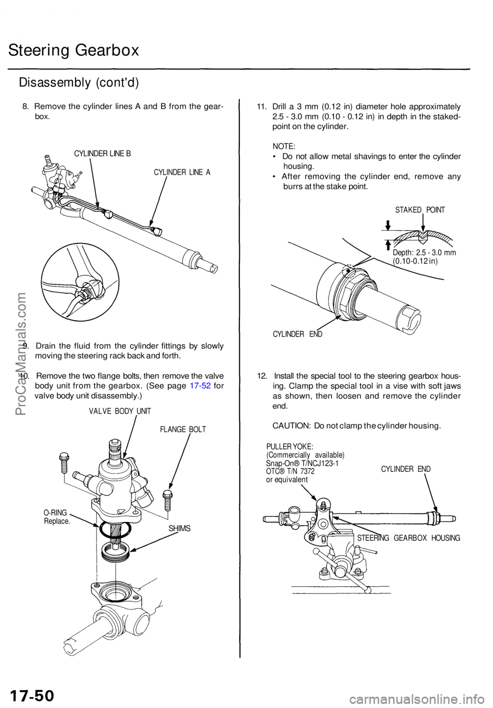
8. Remov e th e cylinde r line s A an d B fro m th e gear -
box.
CYLINDE R LIN E B
CYLINDE R LIN E A
9. Drai n th e flui d fro m th e cylinde r fitting s b y slowl y
movin g th e steerin g rac k bac k an d forth .
10 . Remov e th e tw o flang e bolts , the n remov e th e valv e
bod y uni t fro m th e gearbox . (Se e pag e 17-5 2 fo r
valv e bod y uni t disassembly. )
VALVE BOD Y UNI T
FLANG E BOL T
O-RIN G
Replace .
11. Dril l a 3 mm (0.1 2 in ) diamete r hol e approximatel y
2. 5 - 3. 0 m m (0.1 0 - 0.1 2 in ) i n dept h in th e staked -
poin t o n th e cylinder .
NOTE:
• D o no t allo w meta l shaving s t o ente r th e cylinde r
housing .
• Afte r removin g th e cylinde r end , remov e an y
burr s a t th e stak e point .
STAKE D POIN T
CYLINDE R EN D
12. Instal l th e specia l too l t o th e steerin g gearbo x hous -
ing . Clam p th e specia l too l i n a vis e wit h sof t jaw s
a s shown , the n loose n an d remov e th e cylinde r
end.
CAUTION : D o no t clam p th e cylinde r housing .
PULLER YOKE :
(Commerciall y available )
Snap-On® T/NCJ123- 1OTC® T/ N 737 2or equivalen t
CYLINDER EN D
STEERIN G GEARBO X HOUSIN G
SHIMS
Depth : 2. 5 - 3. 0 m m(0.10-0.1 2 in )
ProCarManuals.com
Page 1195 of 1771
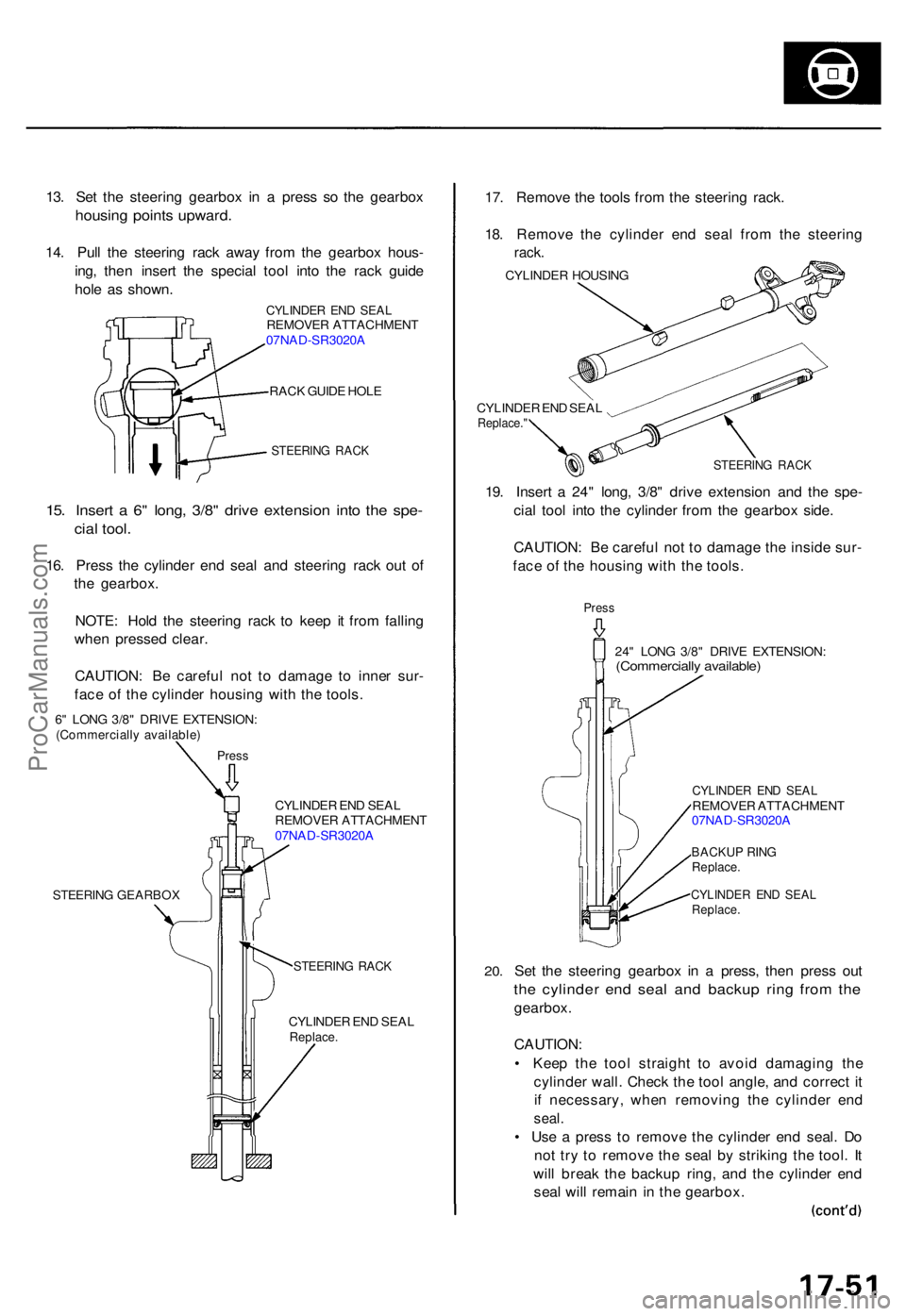
13. Se t th e steerin g gearbo x i n a pres s s o th e gearbo x
housing point s upward .
14. Pul l th e steerin g rac k awa y fro m th e gearbo x hous -
ing , the n inser t th e specia l too l int o th e rac k guid e
hol e a s shown .
CYLINDE R EN D SEA LREMOVE R ATTACHMEN T
07NA D-SR3020 A
RAC K GUID E HOL E
STEERIN G RAC K
15. Inser t a 6 " long , 3/8 " driv e extensio n int o th e spe -
cial tool .
16. Pres s th e cylinde r en d sea l an d steerin g rac k ou t o f
th e gearbox .
NOTE : Hol d th e steerin g rac k t o kee p i t fro m fallin g
whe n presse d clear .
CAUTION : B e carefu l no t t o damag e t o inne r sur -
fac e o f th e cylinde r housin g wit h th e tools .
6" LON G 3/8 " DRIV E EXTENSION :(Commerciall y available )
Press
CYLINDE R EN D SEA L
REMOVE R ATTACHMEN T
07NA D-SR3020 A
STEERIN G GEARBO X
STEERING RAC K
CYLINDE R EN D SEA LReplace .
17. Remov e th e tool s fro m th e steerin g rack .
18 . Remov e th e cylinde r en d sea l fro m th e steerin g
rack.
CYLINDE R HOUSIN G
CYLINDE R EN D SEA L
Replace. "
STEERIN G RAC K
19. Inser t a 24 " long , 3/8 " driv e extensio n an d th e spe -
cia l too l int o th e cylinde r fro m th e gearbo x side .
CAUTION : B e carefu l no t t o damag e th e insid e sur -
fac e o f th e housin g wit h th e tools .
Press
24" LON G 3/8 " DRIV E EXTENSION :(Commercially available )
20.
CYLINDE R EN D SEA LREMOVE R ATTACHMEN T
07NA D-SR3020 A
BACKU P RIN GReplace .
CYLINDE R EN D SEA LReplace .
Set th e steerin g gearbo x i n a press , the n pres s ou t
the cylinde r en d sea l an d backu p rin g fro m th e
gearbox .
CAUTION :
• Kee p th e too l straigh t t o avoi d damagin g th e
cylinde r wall . Chec k th e too l angle , an d correc t i t
i f necessary , whe n removin g th e cylinde r en d
seal .
• Us e a pres s t o remov e th e cylinde r en d seal . D o
no t tr y t o remov e th e sea l b y strikin g th e tool . I t
wil l brea k th e backu p ring , an d th e cylinde r en d
sea l wil l remai n in th e gearbox .
ProCarManuals.com
Page 1196 of 1771
Steering Gearbo x
Disassembl y (cont'd )
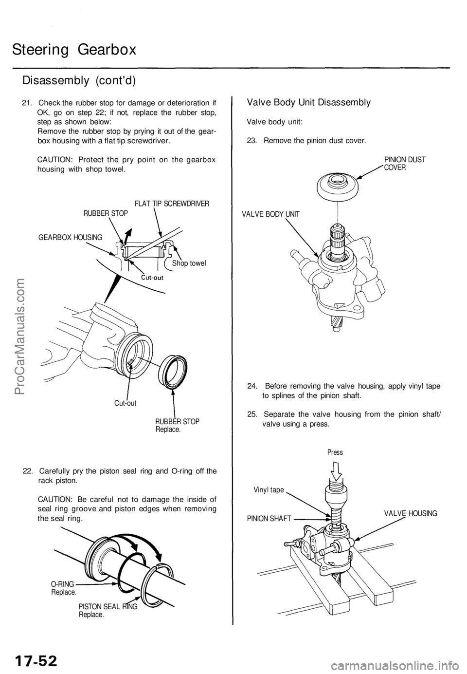
21. Chec k th e rubbe r sto p fo r damag e o r deterioratio n i f
OK , g o o n ste p 22 ; i f not , replac e th e rubbe r stop ,
ste p a s show n below :
Remov e th e rubbe r sto p b y pryin g i t ou t o f th e gear -
box housin g wit h a fla t ti p screwdriver .
CAUTION: Protec t th e pr y poin t o n th e gearbo x
housin g wit h sho p towel .
FLAT TI P SCREWDRIVE R
RUBBER STO P
GEARBO X HOUSIN G
Shop towe l
Cut-ou t
RUBBE R STO PReplace .
22. Carefull y pr y th e pisto n sea l rin g an d O-rin g of f th e
rac k piston .
CAUTION : B e carefu l no t t o damag e th e insid e o f
sea l rin g groov e an d pisto n edge s whe n removin g
th e sea l ring .
O-RIN GReplace .
PISTON SEA L RIN GReplace .
Valve Bod y Uni t Disassembl y
Valve bod y unit :
23 . Remov e th e pinio n dus t cover .
VALVE BOD Y UNI T
PINIO N DUS TCOVE R
24. Befor e removin g th e valv e housing , appl y viny l tap e
t o spline s o f th e pinio n shaft .
25 . Separat e th e valv e housin g fro m th e pinio n shaft /
valv e usin g a press .
Vinyl tap e
Pres s
PINIO N SHAF TVALVE HOUSIN G
ProCarManuals.com
Page 1197 of 1771
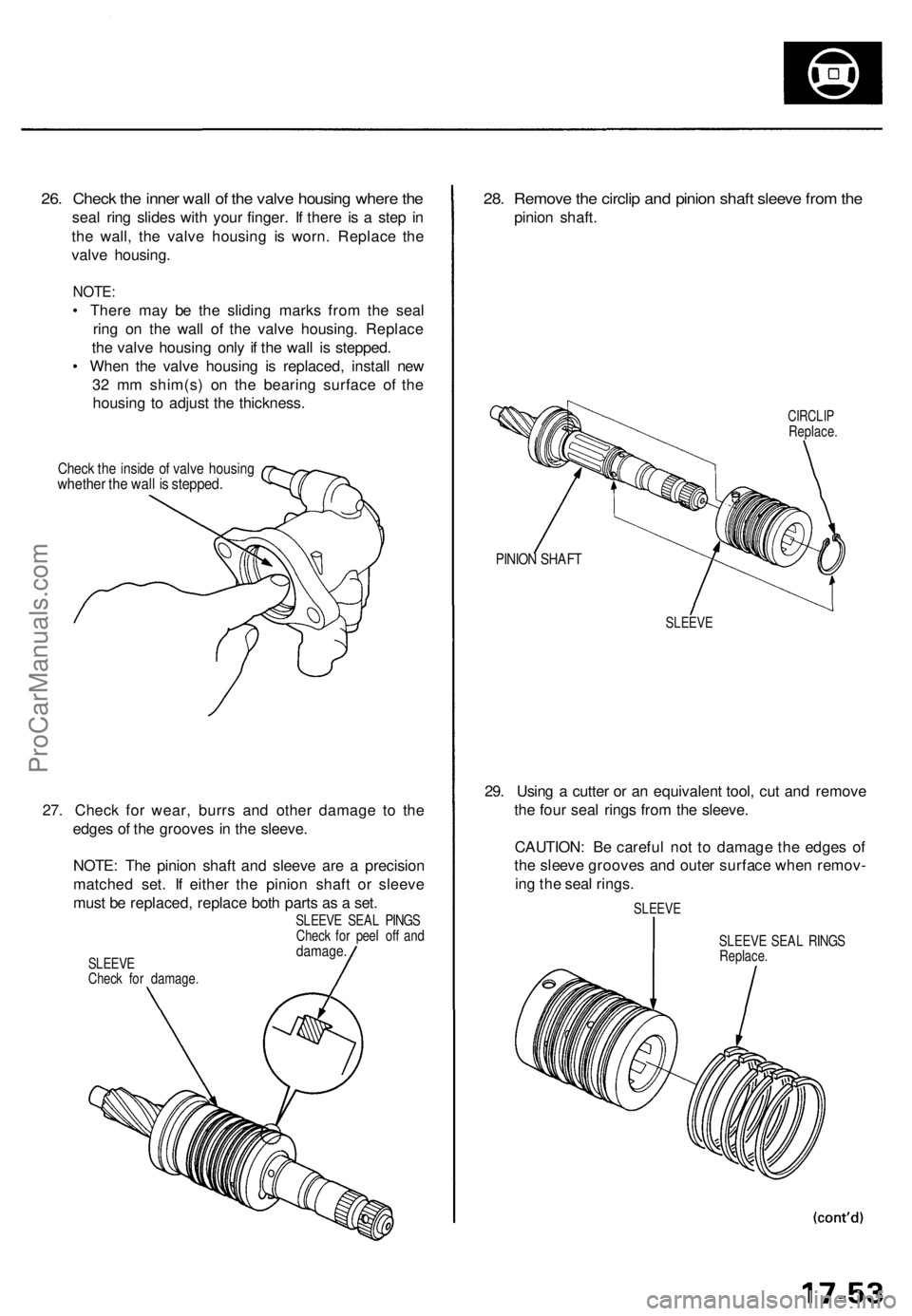
26. Check the inner wall of the valve housing where the
seal ring slides with your finger. If there is a step in
the wall, the valve housing is worn. Replace the
valve housing.
NOTE:
• There may be the sliding marks from the seal
ring on the wall of the valve housing. Replace
the valve housing only if the wall is stepped.
• When the valve housing is replaced, install new
32 mm shim(s) on the bearing surface of the
housing to adjust the thickness.
Check the inside of valve housing
whether the wall is stepped.
27. Check for wear, burrs and other damage to the
edges of the grooves in the sleeve.
NOTE: The pinion shaft and sleeve are a precision
matched set. If either the pinion shaft or sleeve
must be replaced, replace both parts as a set.
SLEEVE SEAL PINGS
Check for peel off and
damage.
SLEEVE
Check for damage.
28. Remove the circlip and pinion shaft sleeve from the
pinion shaft.
CIRCLIP
Replace.
PINION SHAFT
SLEEVE
29. Using a cutter or an equivalent tool, cut and remove
the four seal rings from the sleeve.
CAUTION: Be careful not to damage the edges of
the sleeve grooves and outer surface when remov-
ing the seal rings.
SLEEVE
SLEEVE SEAL RINGS
Replace.ProCarManuals.com
Page 1198 of 1771
Steering Gearbo x
Disassembl y (cont'd )
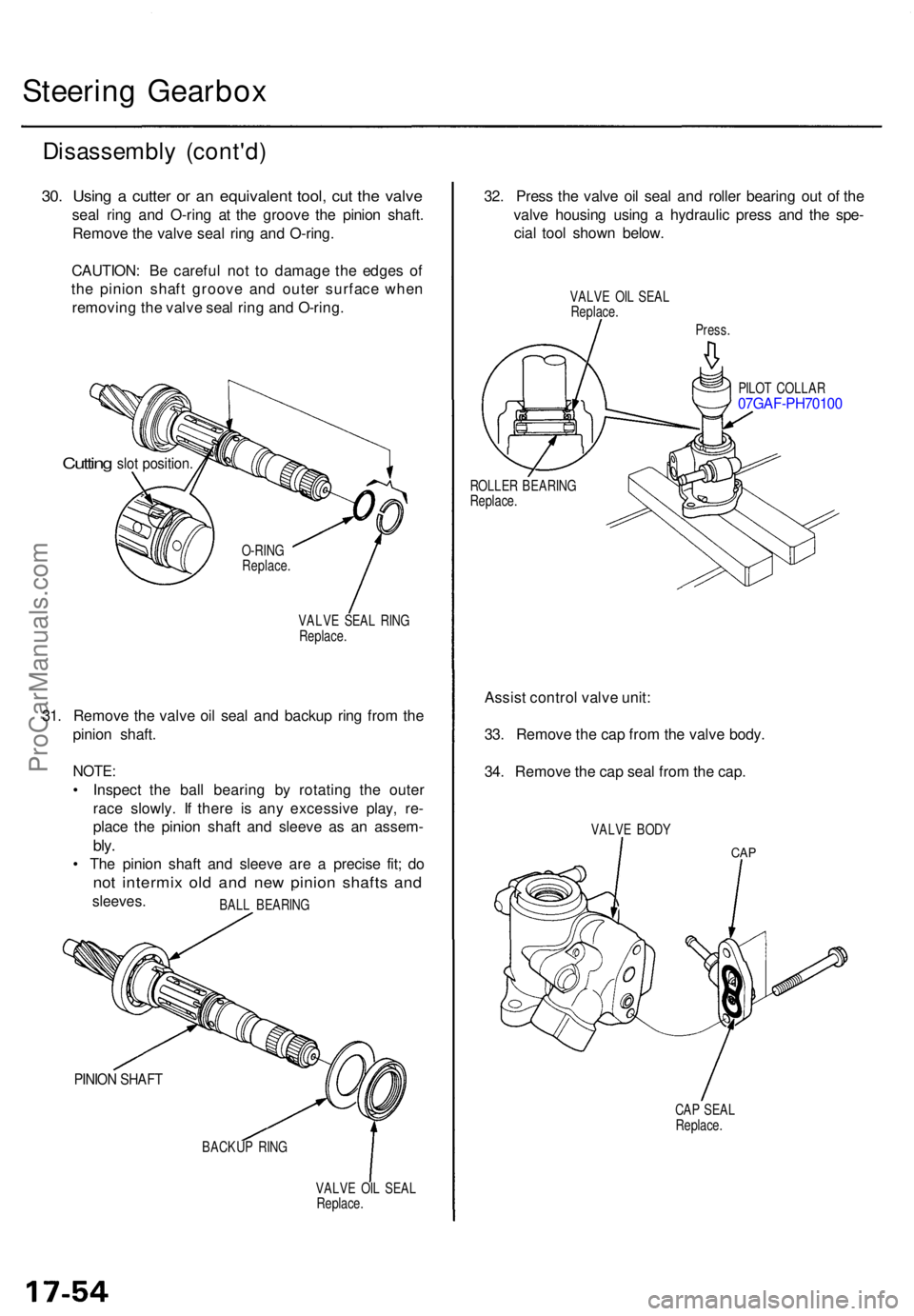
30. Usin g a cutte r o r a n equivalen t tool , cu t th e valv e
seal rin g an d O-rin g a t th e groov e th e pinio n shaft .
Remov e th e valv e sea l rin g an d O-ring .
CAUTION : B e carefu l no t t o damag e th e edge s o f
th e pinio n shaf t groov e an d oute r surfac e whe n
removin g th e valv e sea l rin g an d O-ring .
Cutting slot position .
VALVE SEA L RIN G
Replace .
31. Remov e th e valv e oi l sea l an d backu p rin g fro m th e
pinio n shaft .
NOTE:
• Inspec t th e bal l bearin g b y rotatin g th e oute r
rac e slowly . I f ther e i s an y excessiv e play , re -
plac e th e pinio n shaf t an d sleev e a s a n assem -
bly.
• Th e pinio n shaf t an d sleev e ar e a precis e fit ; d o
no t intermi x ol d an d ne w pinio n shaft s an d
sleeves .
PINION SHAF T
BACKU P RIN G
VALVE OI L SEA L
Replace .
32. Pres s th e valv e oi l sea l an d rolle r bearin g ou t o f th e
valv e housin g usin g a hydrauli c pres s an d th e spe -
cia l too l show n below .
VALVE OI L SEA L
Replace .
Press.
PILO T COLLA R
07GAF-PH7010 0
ROLLER BEARIN G
Replace .
Assist contro l valv e unit :
33 . Remov e th e ca p fro m th e valv e body .
34 . Remov e th e ca p sea l fro m th e cap .
VALV E BOD Y
CAP
CAP SEA L
Replace .
O-RIN
G
Replace .
BAL L BEARIN G
ProCarManuals.com
Page 1199 of 1771
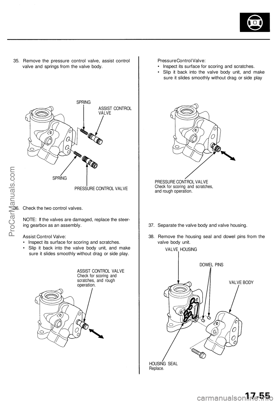
35. Remov e th e pressur e contro l valve , assis t contro l
valv e an d spring s fro m th e valv e body .
SPRIN G
ASSIS T CONTRO L
VALVE
SPRIN G
PRESSUR E CONTRO L VALV E
36. Chec k th e tw o contro l valves .
NOTE : I f th e valve s ar e damaged , replac e th e steer -
in g gearbo x a s a n assembly .
Assis t Contro l Valve :
• Inspec t it s surfac e fo r scorin g an d scratches .
• Sli p i t bac k int o th e valv e bod y unit , an d mak e
sur e it slide s smoothl y withou t dra g o r sid e play .
ASSIS T CONTRO L VALV E
Chec k fo r scorin g an d
scratches , an d roug h
operation .
Pressure Contro l Valve :
• Inspec t it s surfac e fo r scorin g an d scratches .
• Sli p i t bac k int o th e valv e bod y unit , an d mak e
sur e i t slide s smoothl y withou t dra g o r sid e pla y
PRESSUR E CONTRO L VALV E
Chec k fo r scorin g an d scratches ,
and roug h operation .
37. Separat e th e valv e bod y an d valv e housing .
38 . Remov e th e housin g sea l an d dowe l pin s fro m th e
valv e bod y unit .
VALV E HOUSIN G
DOWE L PIN S
VALV E BOD Y
HOUSIN G SEA L
Replace .
ProCarManuals.com
Page 1200 of 1771
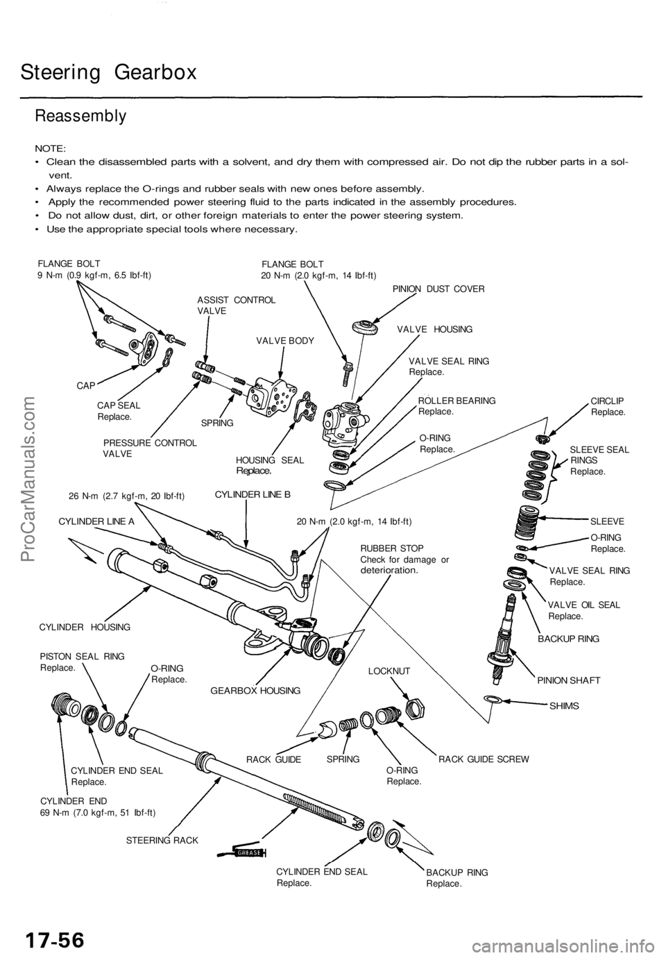
Steering Gearbo x
Reassembl y
NOTE:
• Clea n th e disassemble d part s wit h a solvent , an d dr y the m wit h compresse d air . D o no t di p th e rubbe r part s in a sol -
vent .
• Alway s replac e th e O-ring s an d rubbe r seal s wit h ne w one s befor e assembly .
• Appl y th e recommende d powe r steerin g flui d t o th e part s indicate d i n th e assembl y procedures .
• D o no t allo w dust , dirt , o r othe r foreig n material s t o ente r th e powe r steerin g system .
• Us e th e appropriat e specia l tool s wher e necessary .
FLANGE BOL T
9 N- m (0. 9 kgf-m , 6. 5 Ibf-ft ) FLANG
E BOL T
2 0 N- m (2. 0 kgf-m , 1 4 Ibf-ft )
PINIO N DUS T COVE R
CYLINDE R HOUSIN G
PISTO N SEA L RIN G
Replace . CIRCLI
P
Replace .
SLEEV E SEA L
RING S
Replace .
SLEEV E
O-RIN G
Replace .
VALV E SEA L RIN G
Replace .
VALV E OI L SEA L
Replace .
BACKUP RIN G
PINIO N SHAF T
SHIMS
CYLINDE R EN D
6 9 N- m (7. 0 kgf-m , 5 1 Ibf-ft )
STEERIN G RAC K
CYLINDER EN D SEA L
Replace . BACKU
P RIN G
Replace .
ASSIST CONTRO L
VALV E
VALVE BOD Y VALV
E HOUSIN G
VALV E SEA L RIN G
Replace .
ROLLE R BEARIN G
Replace .
O-RIN G
Replace .
SPRIN
G
CAP
CA P SEA L
Replace .
HOUSING SEA L
Replace .
CYLINDE R LIN E B
20 N- m (2. 0 kgf-m , 1 4 Ibf-ft )
RUBBE R STO P
Chec k fo r damag e o r
deterioration .
LOCKNUT
GEARBO X HOUSIN G
RACK GUID E SPRIN
G
O-RING
Replace .RAC
K GUID E SCRE W
PRESSUR
E CONTRO L
VALV E
2 6 N- m (2. 7 kgf-m , 2 0 Ibf-ft )
CYLINDE R LIN E A
O-RIN GReplace .
CYLINDE R EN D SEA L
Replace .
ProCarManuals.com