ACURA TL 1995 Service Repair Manual
Manufacturer: ACURA, Model Year: 1995, Model line: TL, Model: ACURA TL 1995Pages: 1771, PDF Size: 62.49 MB
Page 1341 of 1771
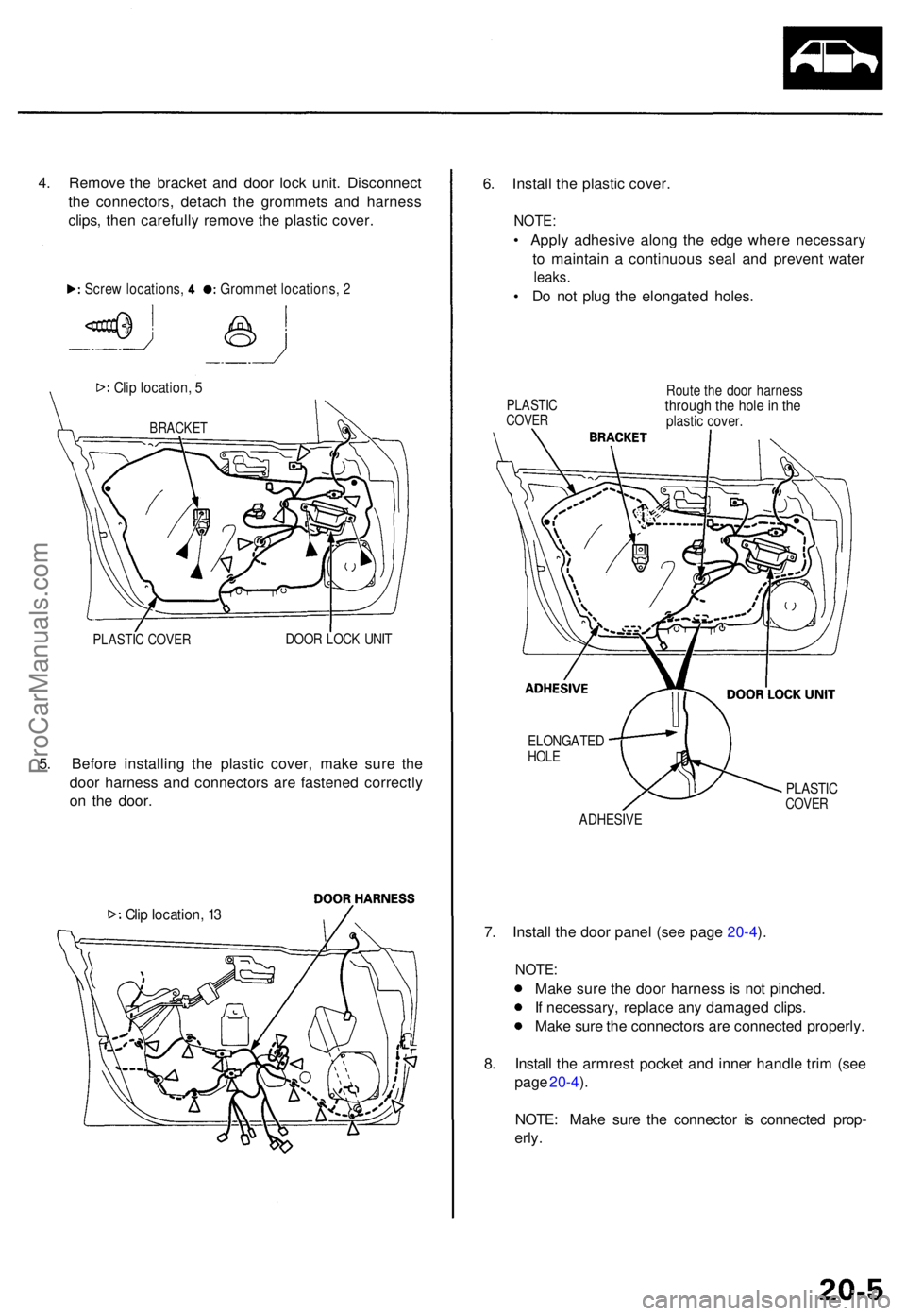
4. Remov e th e bracke t an d doo r loc k unit . Disconnec t
th e connectors , detac h th e grommet s an d harnes s
clips , the n carefull y remov e th e plasti c cover .
Clip location , 5
BRACKE T
PLASTIC COVE RDOOR LOC K UNI T
5. Befor e installin g th e plasti c cover , mak e sur e th e
doo r harnes s an d connector s ar e fastene d correctl y
o n th e door .
Clip location , 1 3
6. Instal l th e plasti c cover .
NOTE:
• Appl y adhesiv e alon g th e edg e wher e necessar y
t o maintai n a continuou s sea l an d preven t wate r
leaks.
• D o no t plu g th e elongate d holes .
PLASTI CCOVER
Route th e doo r harnes sthrough th e hol e in th eplasti c cover .
ELONGATE DHOLE
PLASTI CCOVERADHESIV E
7. Instal l th e doo r pane l (se e pag e 20-4 ).
NOTE :
Make sur e th e doo r harnes s i s no t pinched .
I f necessary , replac e an y damage d clips .
Mak e sur e th e connector s ar e connecte d properly .
8 . Instal l th e armres t pocke t an d inne r handl e tri m (se e
pag e 20-4 ).
NOTE : Mak e sur e th e connecto r i s connecte d prop -
erly .
Gromme t locations , 2Scre w locations ,
ProCarManuals.com
Page 1342 of 1771
Doors
Outer Handl e Replacemen t
NOTE: Rais e th e glas s fully .
1 . Remove :
• Doo r pane l (se e pag e 20-4 )
• Plasti c cove r (se e pag e 20-5 )
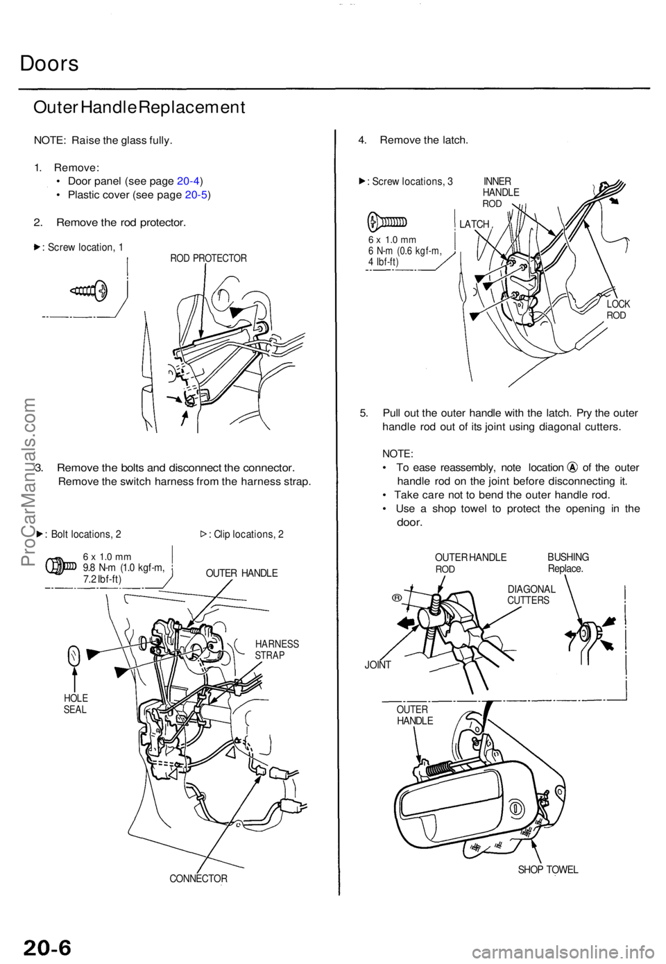
2. Remov e th e ro d protector .
: Scre w location , 1RO D PROTECTO R
3. Remov e th e bolt s an d disconnec t th e connector .
Remove th e switc h harnes s fro m th e harnes s strap .
: Bol t locations , 2
6 x 1. 0 m m9.8 N- m (1. 0 kgf-m ,
7. 2 Ibf-ft ) :
Cli p locations , 2
OUTE R HANDL E
CONNECTO R
4. Remov e th e latch .
: Scre w locations , 3 INNE RHANDLEROD
6 x 1. 0 m m6 N- m (0. 6 kgf-m ,4 Ibf-ft )
LATCH
5. Pul l ou t th e oute r handl e wit h th e latch . Pr y th e oute r
handl e ro d ou t o f it s join t usin g diagona l cutters .
NOTE:
• T o eas e reassembly , not e locatio n o f th e oute r
handl e ro d o n th e join t befor e disconnectin g it .
• Tak e car e no t t o ben d th e oute r handl e rod .
• Us e a sho p towe l t o protec t th e openin g i n th e
door .
OUTE R HANDL ERODBUSHIN G
Replace .
®
JOINT
SHOP TOWE L
DIAGONA LCUTTERS
HARNES SSTRAP
HOLESEALOUTE RHANDL E
LOCKROD
ProCarManuals.com
Page 1343 of 1771
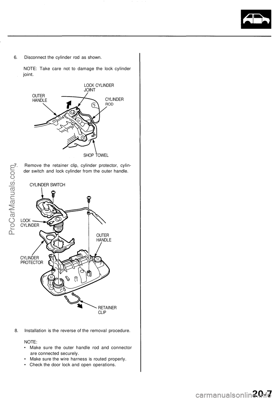
6. Disconnect the cylinder rod as shown.
NOTE: Take care not to damage the lock cylinder
joint.
LOCK CYLINDER
JOINT
OUTER
HANDLE
CYLINDER
ROD
SHOP TOWEL
7. Remove the retainer clip, cylinder protector, cylin-
der switch and lock cylinder from the outer handle.
CYLINDER SWITCH
LOCK
CYLINDER
CYLINDER
PROTECTOR
OUTER
HANDLE
RETAINER
CLIP
8. Installation is the reverse of the removal procedure.
NOTE:
• Make sure the outer handle rod and connector
are connected securely.
• Make sure the wire harness is routed properly.
• Check the door lock and open operations.ProCarManuals.com
Page 1344 of 1771
Latch Replacemen t
NOTE: Rais e th e glas s fully .
1 . Remove :
• Doo r pane l (se e pag e 20-4 )
• Plasti c cove r (se e pag e 20-5 )
• Oute r handl e (se e pag e 20-6 )
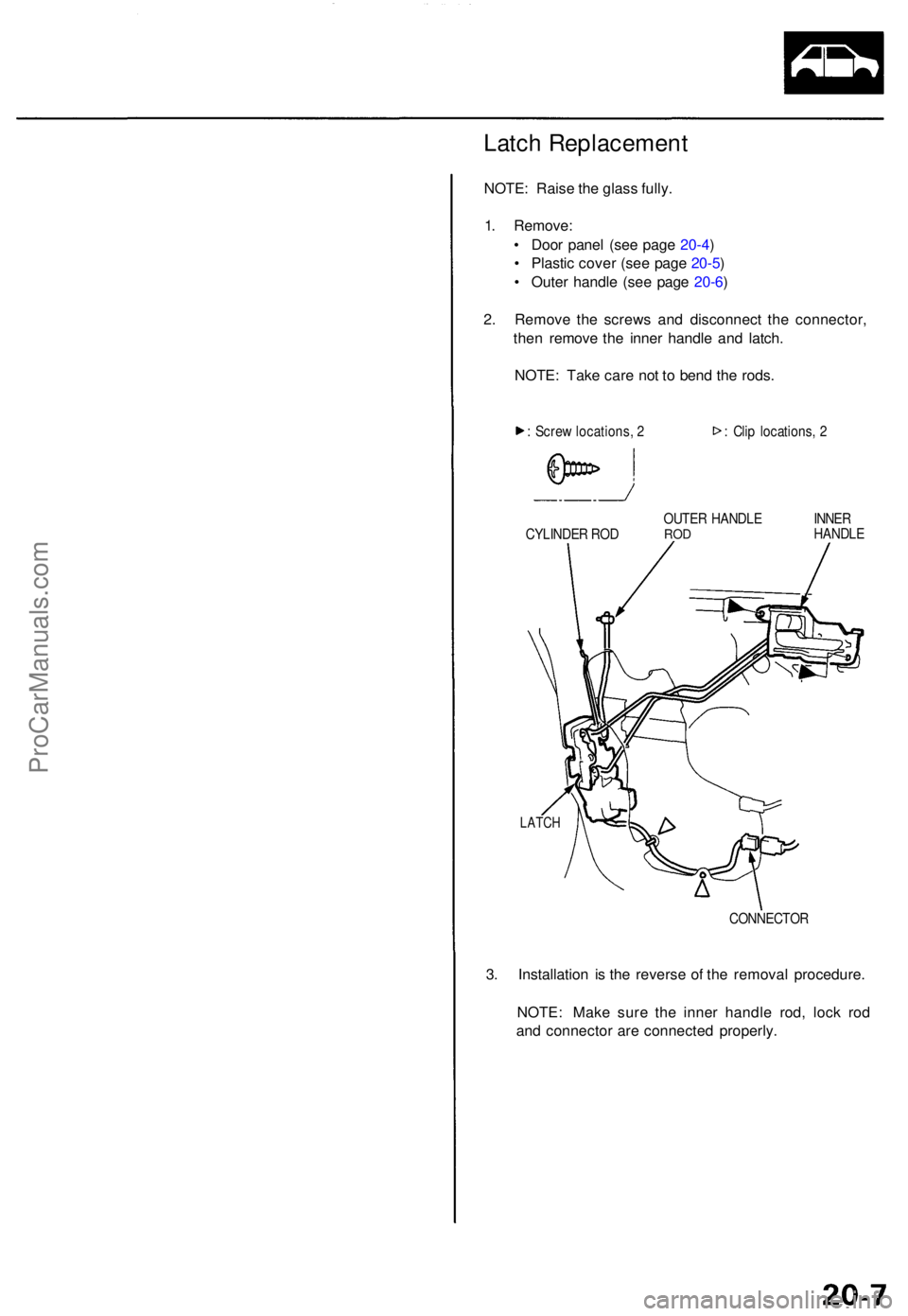
2 . Remov e th e screw s an d disconnec t th e connector ,
the n remov e th e inne r handl e an d latch .
NOTE : Tak e car e no t t o ben d th e rods .
: Scre w locations , 2 : Cli p locations , 2
CYLINDE R RO D OUTE
R HANDL E
RODINNE R
HANDL E
LATCH
CONNECTO R
3. Installatio n i s th e revers e o f th e remova l procedure .
NOTE : Mak e sur e th e inne r handl e rod , loc k ro d
an d connecto r ar e connecte d properly .
ProCarManuals.com
Page 1345 of 1771
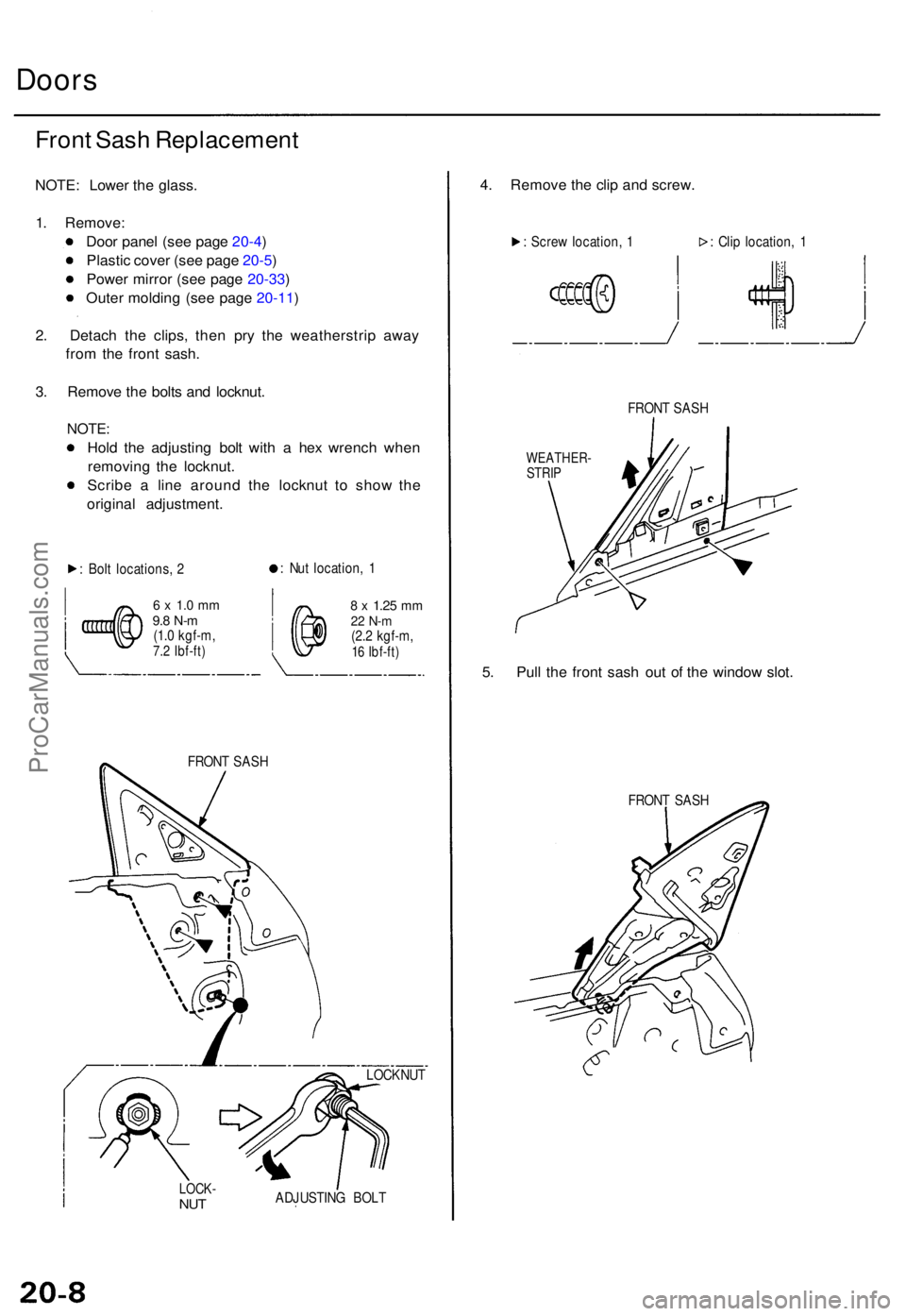
Doors
Front Sas h Replacemen t
NOTE: Lowe r th e glass .
1 . Remove :
Doo r pane l (se e pag e 20-4 )
Plasti c cove r (se e pag e 20-5 )
Powe r mirro r (se e pag e 20-33 )
Oute r moldin g (se e pag e 20-11 )
2 . Detac h th e clips , the n pr y th e weatherstri p awa y
fro m th e fron t sash .
3 . Remov e th e bolt s an d locknut .
NOTE:
Hold th e adjustin g bol t wit h a he x wrenc h whe n
removin g th e locknut .
Scrib e a lin e aroun d th e locknu t t o sho w th e
origina l adjustment .
: Bol t locations , 2 :
Nu t location , 1
6 x 1. 0 m m9.8 N- m(1.0 kgf-m ,7.2 Ibf-ft )
8 x 1.2 5 mm22 N- m(2.2 kgf-m ,16 Ibf-ft )
FRON T SAS H
LOCK -NUTADJUSTIN G BOL T
4. Remov e th e cli p an d screw .
: Scre w location , 1 : Cli p location , 1
FRON T SAS H
WEATHER -
STRI P
5. Pul l th e fron t sas h ou t o f th e windo w slot .
FRON T SAS H
LOCKNU T
ProCarManuals.com
Page 1346 of 1771
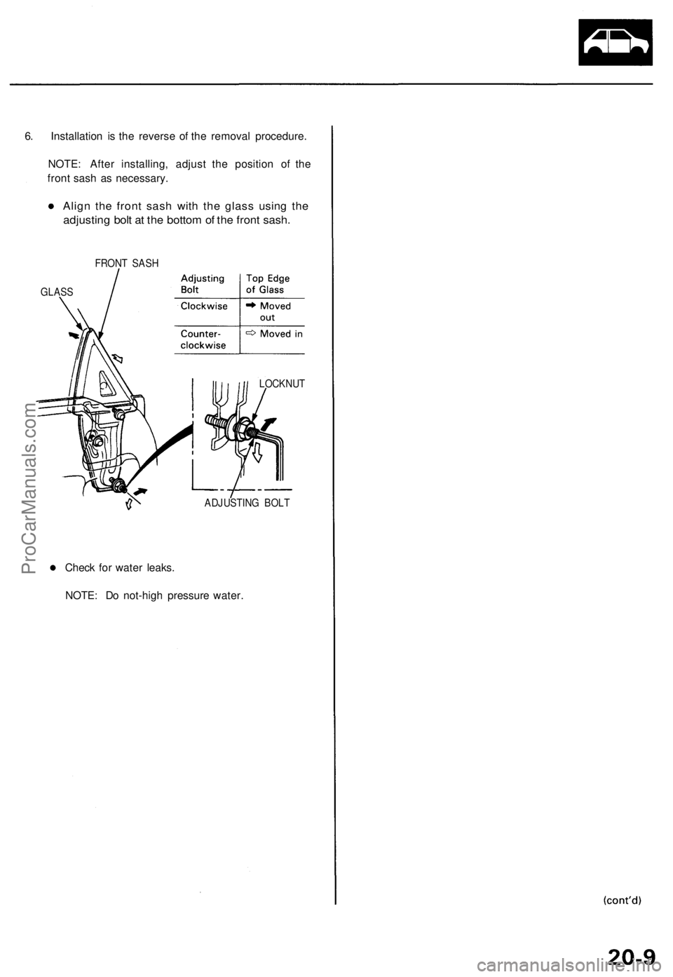
6. Installation is the reverse of the removal procedure.
NOTE: After installing, adjust the position of the
front sash as necessary.
Align the front sash with the glass using the
adjusting bolt at the bottom of the front sash.
FRONT SASH
GLASS
LOCKNUT
ADJUSTING BOLT
Check for water leaks.
NOTE: Do not-high pressure water.ProCarManuals.com
Page 1347 of 1771
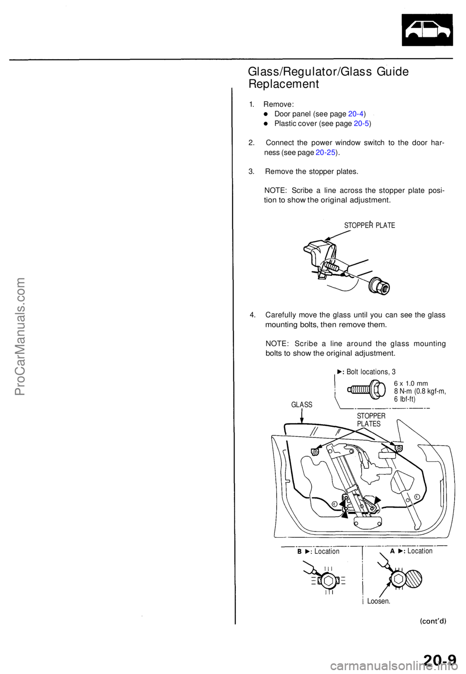
Glass/Regulator/Glass Guid e
Replacemen t
1. Remove :
Doo r pane l (se e pag e 20-4 )
Plasti c cove r (se e pag e 20-5 )
2 . Connec t th e powe r windo w switc h t o th e doo r har -
nes s (se e pag e 20-25 ).
3 . Remov e th e stoppe r plates .
NOTE : Scrib e a lin e acros s th e stoppe r plat e posi -
tion to sho w th e origina l adjustment .
STOPPER PLAT E
4. Carefull y mov e th e glas s unti l yo u ca n se e th e glas s
mountin g bolts , the n remov e them .
NOTE : Scrib e a lin e aroun d th e glas s mountin g
bolts t o sho w th e origina l adjustment .
Bolt locations , 3
GLAS S
6 x 1. 0 m m8 N- m (0. 8 kgf-m ,6 Ibf-ft )
Loosen .
STOPPE R
PLATE S
Locatio n Locatio
n
ProCarManuals.com
Page 1348 of 1771
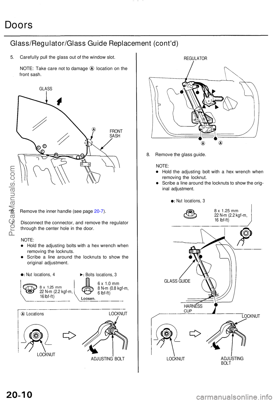
Doors
Glass/Regulator/Glas s Guid e Replacemen t (cont'd )
5. Carefull y pul l th e glas s ou t o f th e windo w slot .
NOTE : Tak e car e no t t o damag e locatio n o n th e
fron t sash .
GLAS S
FRONTSASH
6. Remov e th e inne r handl e (se e pag e 20-7 ).
7 . Disconnec t th e connector , an d remov e th e regulato r
throug h th e cente r hol e i n th e door .
NOTE :
Hold th e adjustin g bolt s wit h a he x wrenc h whe n
removin g th e locknuts .
Scrib e a lin e aroun d th e locknut s t o sho w th e
origina l adjustment .
Nut locations , 4
Bolts locations , 3
8 x 1.2 5 mm22 N- m (2. 2 kgf-m ,
1 6 Ibf-ft )
Location s
6 x 1. 0 m m8 N- m (0. 8 kgf-m ,
6 Ibf-ft )
LOCKNU T
LOCKNU T
ADJUSTING BOL T
REGULATO R
8. Remov e th e glas s guide .
NOTE:
Hold th e adjustin g bol t wit h a he x wrenc h whe n
removin g th e locknut .
Scrib e a lin e aroun d th e locknut s t o sho w th e orig -
ina l adjustment .
Nut locations , 3
8 x 1.2 5 mm22 N- m (2. 2 kgf-m ,
1 6 Ibf-ft )
LOCKNU T
LOCKNU T
ADJUSTIN GBOLT
GLAS S GUID E
HARNES S
CUP
ProCarManuals.com
Page 1349 of 1771
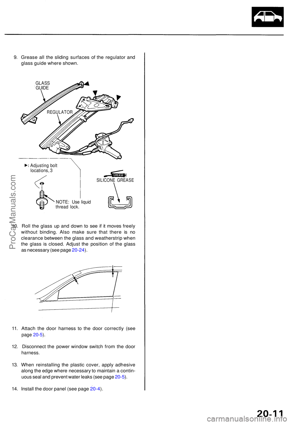
9. Greas e al l th e slidin g surface s o f th e regulato r an d
glas s guid e wher e shown .
GLASSGUIDE
10. Rol l th e glas s u p an d dow n t o se e i f i t move s freel y
withou t binding . Als o mak e sur e tha t ther e i s n o
clearanc e betwee n th e glas s an d weatherstri p whe n
th e glas s i s closed . Adjus t th e positio n o f th e glas s
a s necessar y (se e pag e 20-24 ).
11 . Attac h th e doo r harnes s t o th e doo r correctl y (se e
page 20-5 ).
12 . Disconnec t th e powe r windo w switc h fro m th e doo r
harness .
13. Whe n reinstallin g th e plasti c cover , appl y adhesiv e
alon g th e edg e wher e necessar y to maintai n a contin -
uou s sea l an d preven t wate r leak s (se e pag e 20-5 ).
14 . Instal l th e doo r pane l (se e pag e 20-4 ).
REGULATO R
Adjusting bol tlocations , 3
NOTE : Us e liqui dthrea d lock .
SILICON E GREAS E
ProCarManuals.com
Page 1350 of 1771
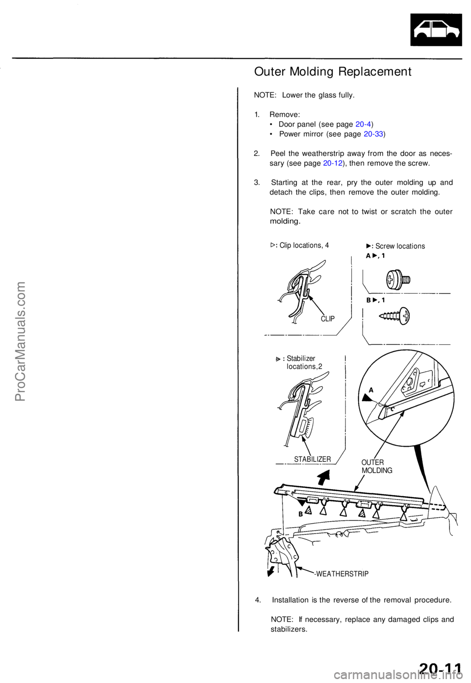
Outer Moldin g Replacemen t
NOTE: Lowe r th e glas s fully .
1 . Remove :
• Doo r pane l (se e pag e 20-4 )
• Powe r mirro r (se e pag e 20-33 )
2 . Pee l th e weatherstri p awa y fro m th e doo r a s neces -
sar y (se e pag e 20-12 ), the n remov e th e screw .
3 . Startin g a t th e rear , pr y th e oute r moldin g u p an d
detac h th e clips , the n remov e th e oute r molding .
NOTE : Tak e car e no t t o twis t o r scratc h th e oute r
molding .
Clip locations , 4
-WEATHERSTRI P
4. Installatio n i s th e revers e o f th e remova l procedure .
NOTE : I f necessary , replac e an y damage d clip s an d
stabilizers .
OUTERMOLDIN G
STABILIZE R
Stabilizer
locations , 2 Scre
w location s
CLIP
ProCarManuals.com