ACURA TL 1995 Service Repair Manual
Manufacturer: ACURA, Model Year: 1995, Model line: TL, Model: ACURA TL 1995Pages: 1771, PDF Size: 62.49 MB
Page 1331 of 1771
Troubleshooting Precautions
Kickback
1. The motor operates when the ABS is functioning, and the fluid in the reservoir is forced out to the master cylinder
causing kickback at the brake pedal.
Pump Motor
1. The pump motor operates when the ABS is functioning.
2. The ABS control unit checks the pump motor operation during initial diagnosis and vehicle starts. You may hear the
faint operation sound at this time, but it is normal.
Brake Fluid Replacement/Air Bleeding
1. Brake fluid replacement and air bleeding procedures are the same as vehicles without ABS. To ease bleeding, start
with the front wheels.
Troubleshooting
1. The troubleshooting flowcharts procedures assume that the cause of the problem is still present and the ABS indica-
tor light is still on. Following the flowchart when the ABS indicator light does not come on can result in incorrect
judgment.
2. Question the customer about the conditions when the problem occurred, and try to reproduce the same conditions
for troubleshooting.
Find out when the ABS indicator light came on, such as during initial diagnosis, during ABS control, after ABS con-
trol, when the vehicle started, when vehicle speed was at 19 mph (30 km/h), when the problem continued for a few
seconds or a few minutes, etc.
3. When the ABS indicator light does not come on during the test-drive, but the troubleshooting is performed based on
the DTC, check for the loose connectors, poor contact of the terminals, etc, before troubleshooting.
4. After troubleshooting, erase the DTC and test-drive the vehicle. Be sure that the ABS indicator light does not come on.
5. The connector illustrations show the female connectors with a single outline and the male connectors with a double
outline.ProCarManuals.com
Page 1332 of 1771
Diagnostic Troubl e Cod e (DTC )
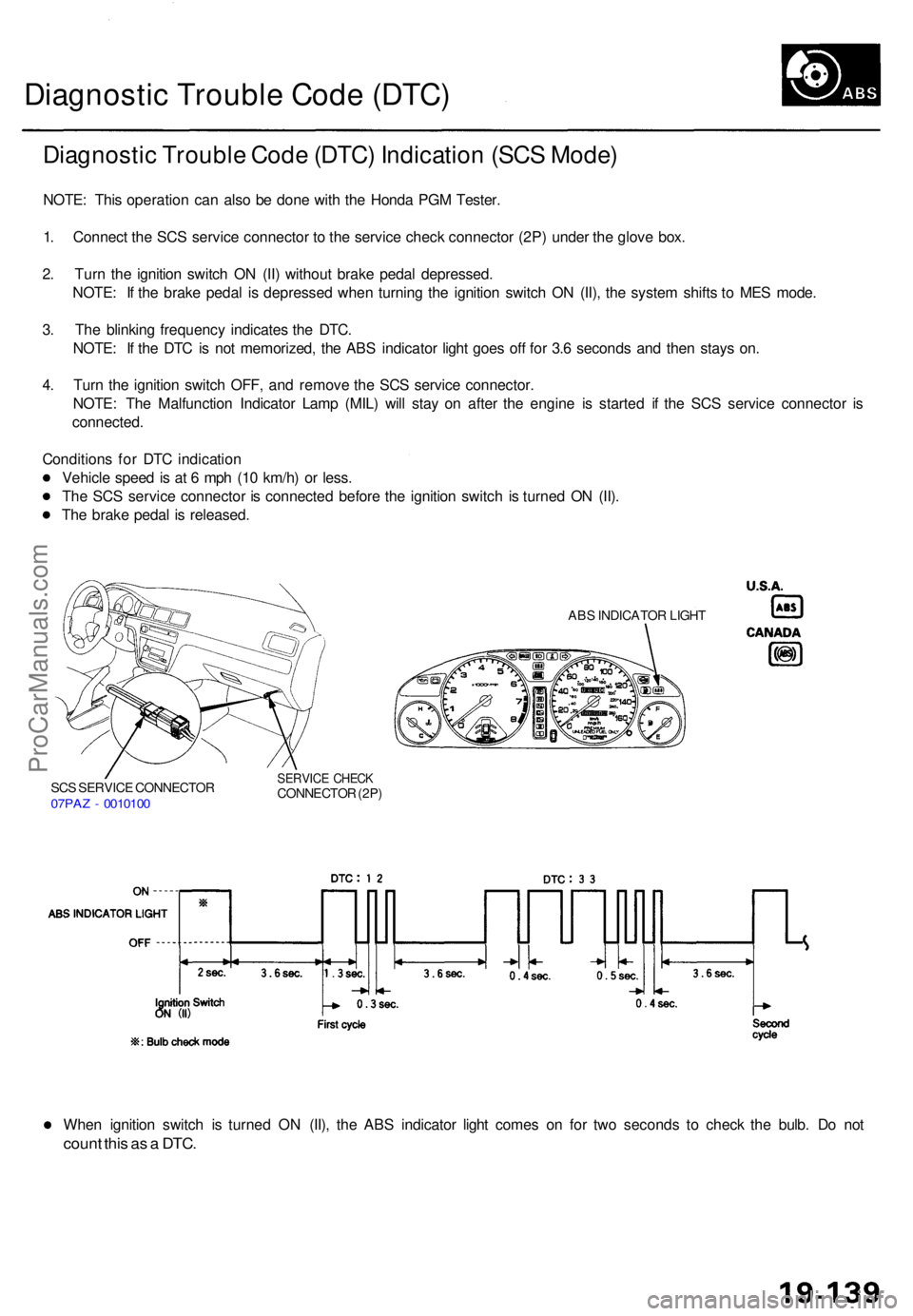
Diagnosti c Troubl e Cod e (DTC ) Indicatio n (SC S Mode )
NOTE: Thi s operatio n ca n als o b e don e wit h th e Hond a PG M Tester .
1 . Connec t th e SC S servic e connecto r t o th e servic e chec k connecto r (2P ) unde r th e glov e box .
2 . Tur n th e ignitio n switc h O N (II ) withou t brak e peda l depressed .
NOTE : I f th e brak e peda l i s depresse d whe n turnin g th e ignitio n switc h O N (II) , th e syste m shift s t o ME S mode .
3 . Th e blinkin g frequenc y indicate s th e DTC .
NOTE : I f th e DT C is no t memorized , th e AB S indicato r ligh t goe s of f fo r 3. 6 second s an d the n stay s on .
4 . Tur n th e ignitio n switc h OFF , an d remov e th e SC S servic e connector .
NOTE : Th e Malfunctio n Indicato r Lam p (MIL ) wil l sta y o n afte r th e engin e i s starte d i f th e SC S servic e connecto r i s
connected .
Condition s fo r DT C indicatio n
Vehicl e spee d is a t 6 mp h (1 0 km/h ) o r less .
Th e SC S servic e connecto r i s connecte d befor e th e ignitio n switc h i s turne d O N (II) .
Th e brak e peda l i s released .
SCS SERVIC E CONNECTO R07PAZ - 001010 0
SERVIC E CHEC KCONNECTO R (2P )
ABS INDICATO R LIGH T
When ignitio n switc h i s turne d O N (II) , th e AB S indicato r ligh t come s o n fo r tw o second s t o chec k th e bulb . D o no t
coun t thi s a s a DTC .
ProCarManuals.com
Page 1333 of 1771
Diagnostic Trouble Code (DTC)
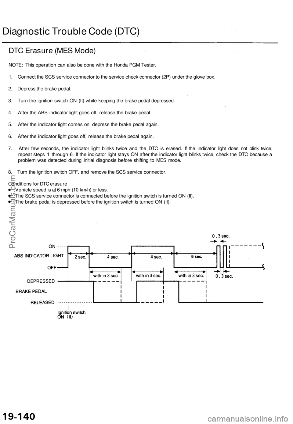
DTC Erasure (MES Mode)
NOTE: This operation can also be done with the Honda PGM Tester.
1. Connect the SCS service connector to the service check connector (2P) under the glove box.
2. Depress the brake pedal.
3. Turn the ignition switch ON (II) while keeping the brake pedal depressed.
4. After the ABS indicator light goes off, release the brake pedal.
5. After the indicator light comes on, depress the brake pedal again.
6. After the indicator light goes off, release the brake pedal again.
7. After few seconds, the indicator light blinks twice and the DTC is erased. If the indicator light does not blink twice,
repeat steps 1 through 6. If the indicator light stays ON after the indicator light blinks twice, check the DTC because a
problem was detected during initial diagnosis before shifting to MES mode.
8. Turn the ignition switch OFF, and remove the SCS service connector.
Conditions for DTC erasure
Vehicle speed is at 6 mph (10 km/h) or less.
The SCS service connector is connected before the ignition switch is turned ON (II).
The brake pedal is depressed before the ignition switch is turned ON (II).ProCarManuals.com
Page 1334 of 1771
Troubleshooting Inde x
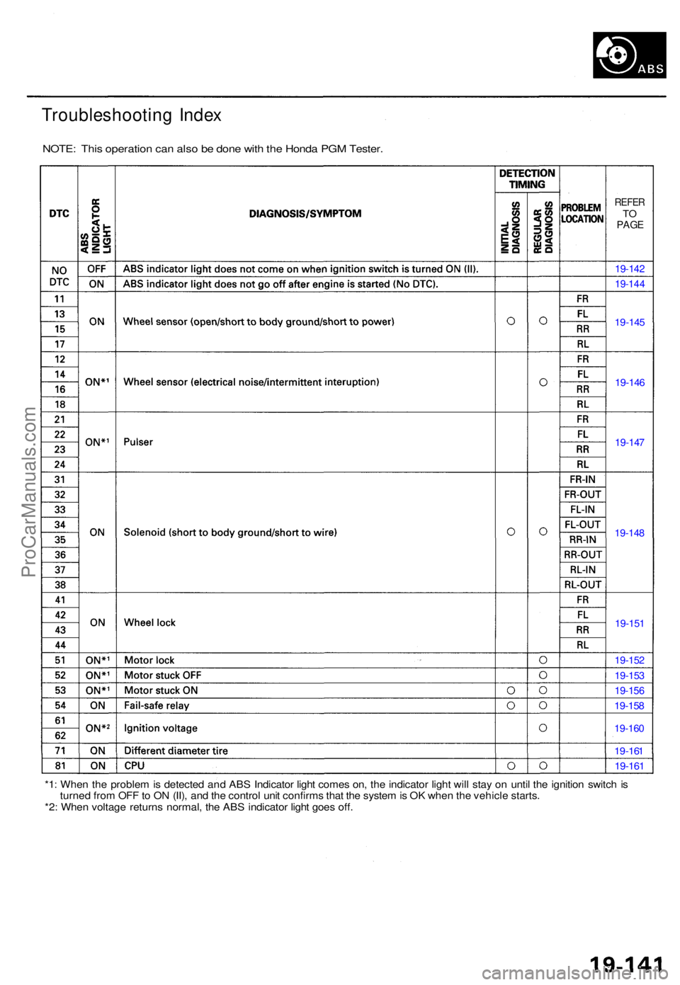
NOTE : Thi s operatio n ca n als o b e don e wit h th e Hond a PG M Tester .
REFERTOPAG E
19-14 2
19-14 4
19-145
19-146
19-147
19-148
19-151
19-152
19-153
19-156
19-158
19-160
19-161
19-161
*1: Whe n th e proble m is detecte d an d AB S Indicato r ligh t come s on , th e indicato r ligh t wil l sta y o n unti l th e ignitio n switc h is
turne d fro m OF F to O N (II) , an d th e contro l uni t confirm s tha t th e syste m is O K whe n th e vehicl e starts .
*2 : Whe n voltag e return s normal , th e AB S indicato r ligh t goe s off .
ProCarManuals.com
Page 1335 of 1771
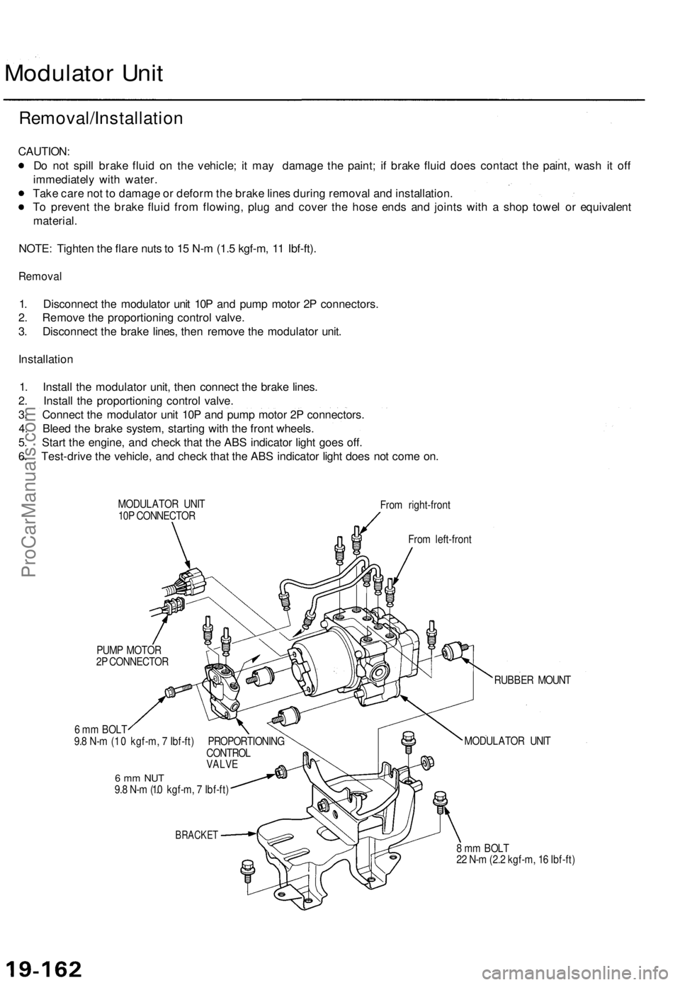
Modulator Unit
Removal/Installation
CAUTION:
Do not spill brake fluid on the vehicle; it may damage the paint; if brake fluid does contact the paint, wash it off
immediately with water.
Take care not to damage or deform the brake lines during removal and installation.
To prevent the brake fluid from flowing, plug and cover the hose ends and joints with a shop towel or equivalent
material.
NOTE: Tighten the flare nuts to 15 N-m (1.5 kgf-m, 11 Ibf-ft).
Removal
1. Disconnect the modulator unit 10P and pump motor 2P connectors.
2. Remove the proportioning control valve.
3. Disconnect the brake lines, then remove the modulator unit.
Installation
1. Install the modulator unit, then connect the brake lines.
2. Install the proportioning control valve.
3. Connect the modulator unit 10P and pump motor 2P connectors.
4. Bleed the brake system, starting with the front wheels.
5. Start the engine, and check that the ABS indicator light goes off.
6. Test-drive the vehicle, and check that the ABS indicator light does not come on.
MODULATOR UNIT
10P CONNECTOR
From right-front
From left-front
PUMP MOTOR
2P CONNECTOR
6 mm BOLT
9.8 N-m (1 .0 kgf-m, 7 Ibf-ft) PROPORTIONING
CONTROL
VALVE
6 mm NUT
9.8 N-m (1.0 kgf-m, 7 Ibf-ft)
BRACKET
RUBBER MOUNT
MODULATOR UNIT
8 mm BOLT
22 N-m (2.2 kgf-m, 16 Ibf-ft)ProCarManuals.com
Page 1336 of 1771
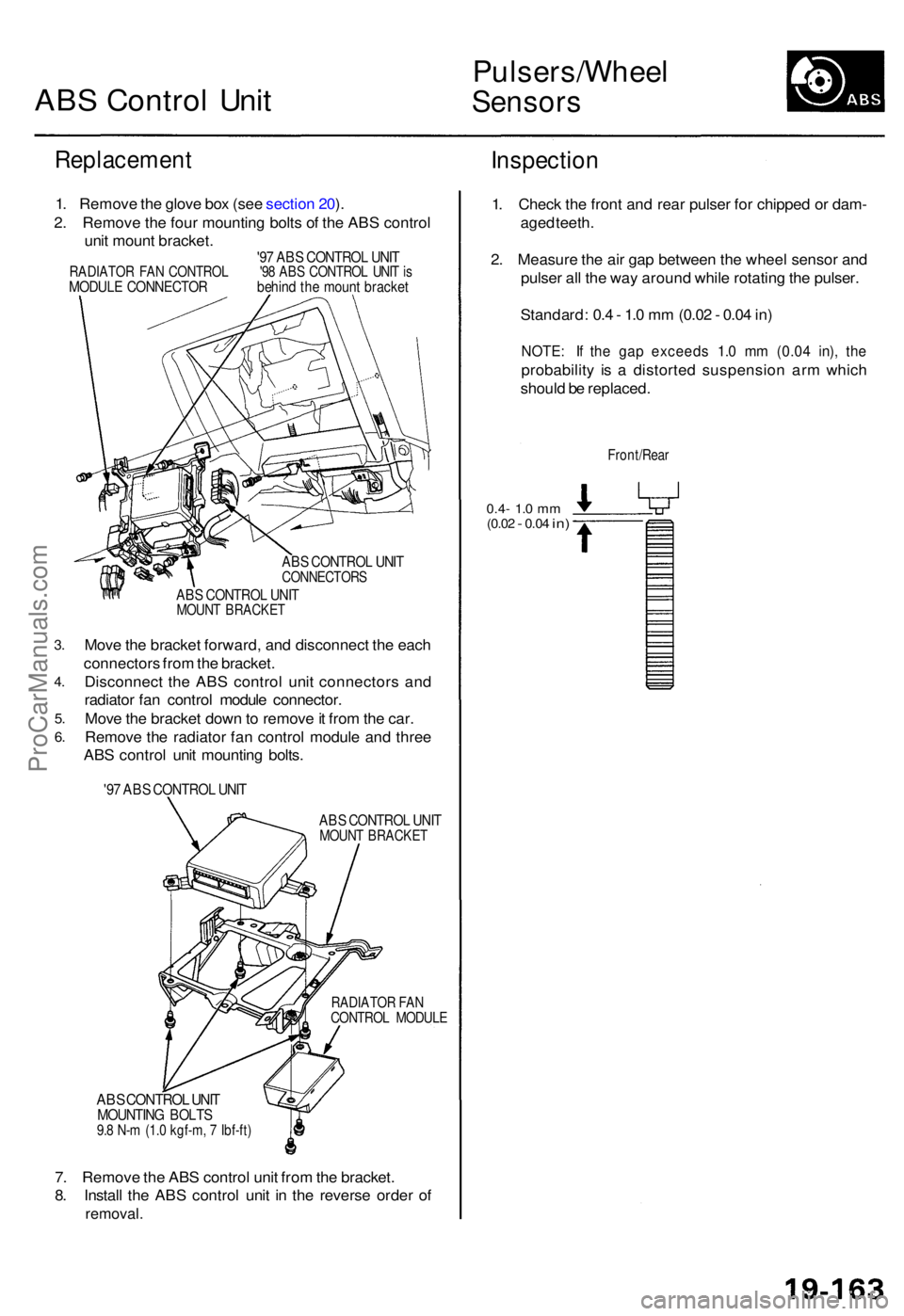
ABS Contro l Uni t
Pulsers/Whee l
Sensors
Replacemen t
1. Remov e th e glov e bo x (se e sectio n 20 ).
2 . Remov e th e fou r mountin g bolt s o f th e AB S contro l
uni t moun t bracket .
'97 AB S CONTRO L UNI TRADIATO R FA N CONTRO L '9 8 AB S CONTRO L UNI T isMODUL E CONNECTO R behin d th e moun t bracke t
3.
4 .
5.
6.
AB S CONTRO L UNI TCONNECTOR S
ABS CONTRO L UNI TMOUN T BRACKE T
Move th e bracke t forward , an d disconnec t th e eac h
connector s fro m th e bracket .
Disconnec t th e AB S contro l uni t connector s an d
radiato r fa n contro l modul e connector .
Mov e th e bracke t dow n to remov e it fro m th e car .
Remov e th e radiato r fa n contro l modul e an d thre e
AB S contro l uni t mountin g bolts .
'97 AB S CONTRO L UNI T
ABS CONTRO L UNI TMOUN T BRACKE T
RADIATO R FA N
CONTRO L MODUL E
ABS CONTRO L UNI TMOUNTIN G BOLT S9.8 N- m (1. 0 kgf-m , 7 Ibf-ft )
7. Remov e th e AB S contro l uni t fro m th e bracket .
8 . Instal l th e AB S contro l uni t i n th e revers e orde r o f
removal .
Inspectio n
1. Chec k th e fron t an d rea r pulse r fo r chippe d o r dam -
age d teeth .
2 . Measur e th e ai r ga p betwee n th e whee l senso r an d
pulse r al l th e wa y aroun d whil e rotatin g th e pulser .
Standard : 0. 4 - 1. 0 m m (0.0 2 - 0.0 4 in )
NOTE : I f th e ga p exceed s 1. 0 m m (0.0 4 in) , th e
probabilit y i s a distorte d suspensio n ar m whic h
shoul d b e replaced .
Front/Rea r
0.4- 1.0 m m(0.0 2 - 0.04 in)
ProCarManuals.com
Page 1337 of 1771
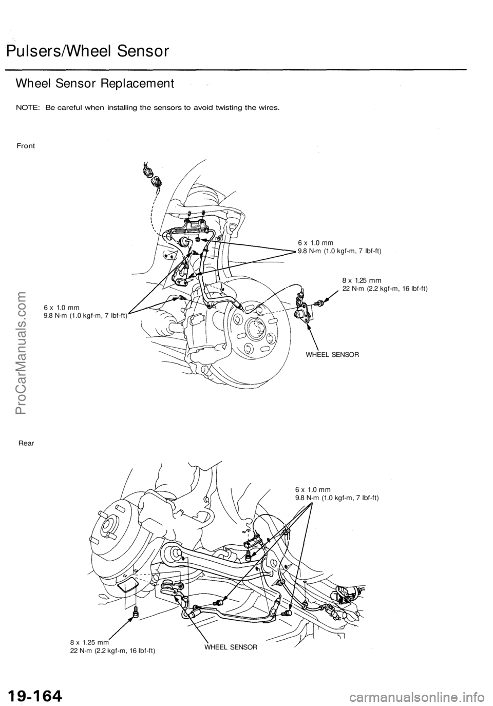
Pulsers/Wheel Sensor
Wheel Sensor Replacement
NOTE: Be careful when installing the sensors to avoid twisting the wires.
Front
6 x 1.0 mm
9.8 N-m (1.0 kgf-m, 7 Ibf-ft)
6 x 1.0 mm
9.8 N-m (1.0 kgf-m, 7 Ibf-ft)
8 x
1.25
mm
22 N-m (2.2 kgf-m, 16 Ibf-ft)
WHEEL SENSOR
Rear
6 x 1.0 mm
9.8 N-m (1.0 kgf-m, 7 Ibf-ft)
8 x
1.25
mm
22 N-m (2.2 kgf-m, 16 Ibf-ft)
WHEEL SENSORProCarManuals.com
Page 1338 of 1771
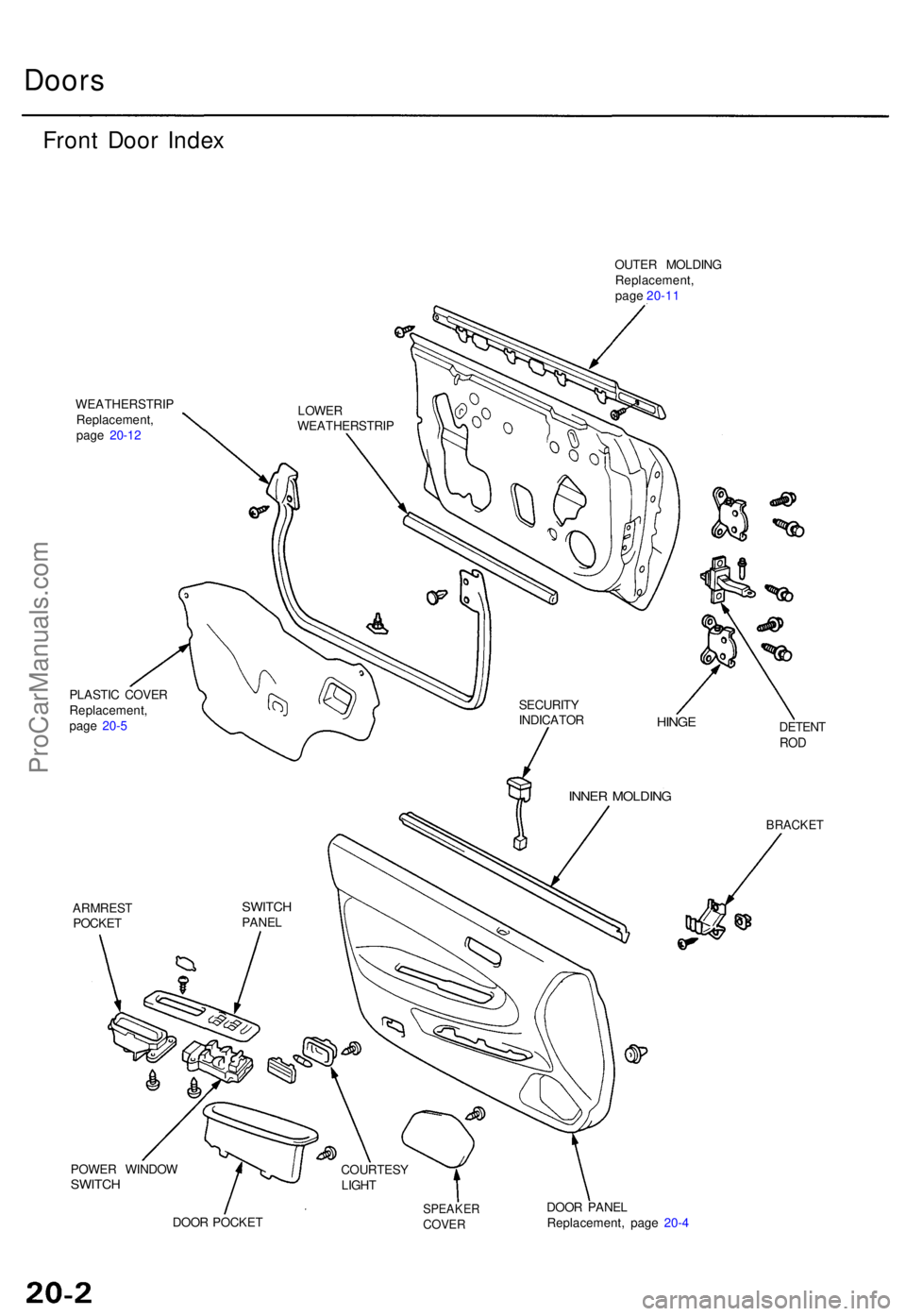
Doors
Front Doo r Inde x
WEATHERSTRI P
Replacement ,
pag e 20-1 2
PLASTI C COVE R
Replacement ,
pag e 20- 5
ARMRES T
POCKE T OUTE
R MOLDIN G
Replacement ,
pag e 20-1 1
POWE R WINDO W
SWITCH
DETEN TROD
BRACKE T
DOOR POCKE TSPEAKE RCOVER
DOOR PANE L
Replacement , pag e 20- 4
SWITC HPANEL
COURTESY
LIGH T
INNER MOLDIN G
HINGE
SECURIT Y
INDICATO R
LOWE
R
WEATHERSTRI P
ProCarManuals.com
Page 1339 of 1771
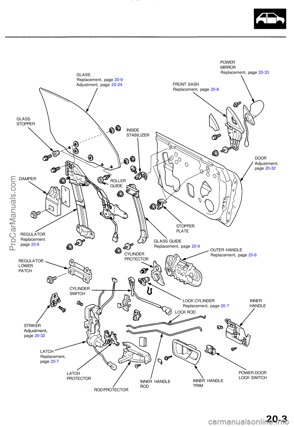
GLASSSTOPPE R
DAMPER
REGULATO RReplacemen t
pag e 20- 9
REGULATO RLOWERPATCH
STRIKE RAdjustment ,page 20-3 2
GLAS SReplacement , pag e 20- 9
Adjustment , pag e 20-2 4
POWE RMIRRO R
Replacement , pag e 20-3 3
DOO RAdjustment ,page 20-3 2
GLAS S GUID E
Replacement , pag e 20- 9
OUTER HANDL E
Replacement , pag e 20- 6
LOC K CYLINDE R INNE R
Replacement , pag e 20- 7 HANDL E
LOC K RO D
LATC H
Replacement ,
pag e 20- 7
LATC H
PROTECTO R
ROD PROTECTO R INNE
R HANDL ETRIM
POWE R DOO R
LOC K SWITC H
CYLINDE RSWITCH
INNER HANDL E
ROD
CYLINDE RPROTECTO R
STOPPERPLATE
ROLLE RGUIDE . INSID
E
STABILIZE R
FRONT SAS H
Replacement , pag e 20- 8
ProCarManuals.com
Page 1340 of 1771
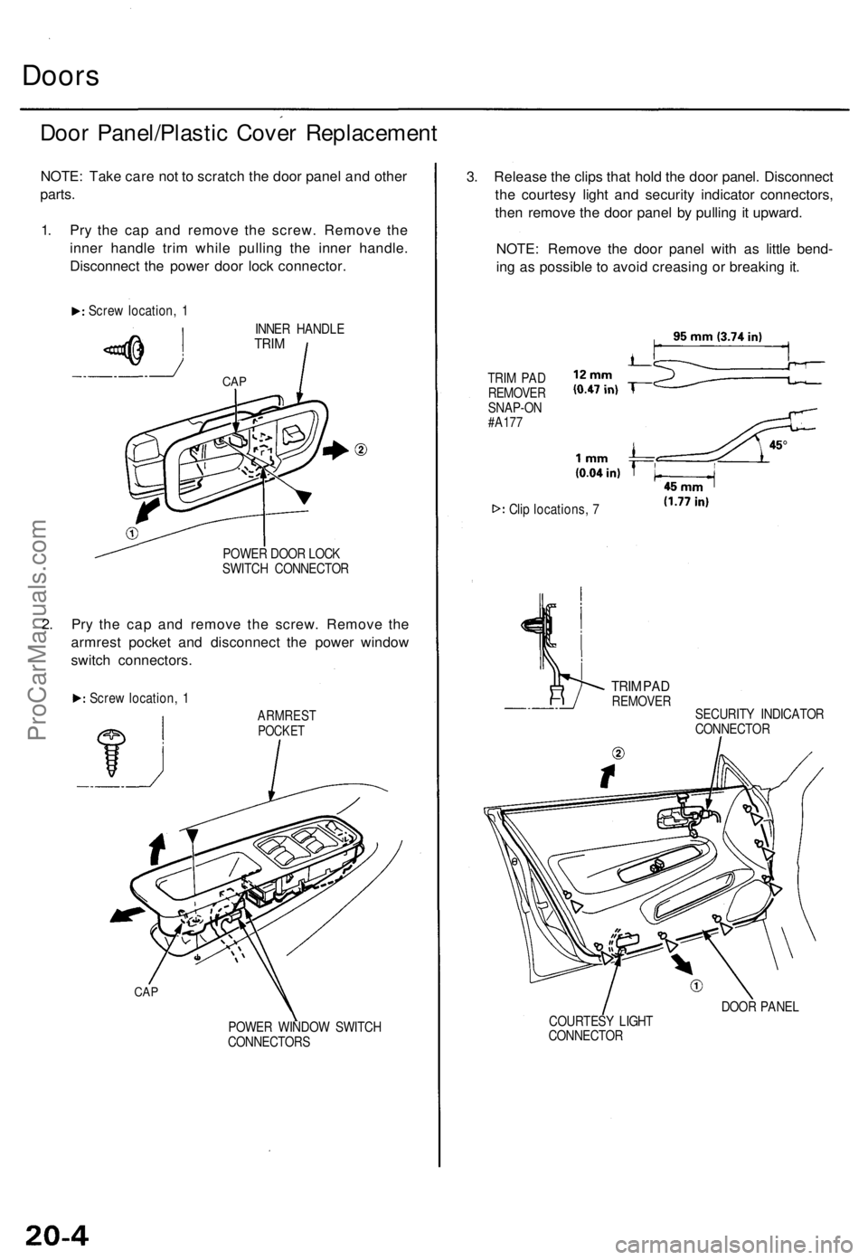
Doors
Door Panel/Plasti c Cove r Replacemen t
NOTE: Tak e car e no t t o scratc h th e doo r pane l an d othe r
parts .
1 . Pr y th e ca p an d remov e th e screw . Remov e th e
inne r handl e tri m whil e pullin g th e inne r handle .
Disconnec t th e powe r doo r loc k connector .
Screw location , 1
INNER HANDL E
TRIM
POWE R DOO R LOC K
SWITC H CONNECTO R
2. Pr y th e ca p an d remov e th e screw . Remov e th e
armres t pocke t an d disconnec t th e powe r windo w
switc h connectors .
Screw location , 1
ARMRES TPOCKET
CAP
POWE R WINDO W SWITC H
CONNECTOR S
3. Releas e th e clip s tha t hol d th e doo r panel . Disconnec t
th e courtes y ligh t an d securit y indicato r connectors ,
the n remov e th e doo r pane l b y pullin g it upward .
NOTE : Remov e th e doo r pane l wit h a s littl e bend -
in g a s possibl e t o avoi d creasin g o r breakin g it .
TRI M PA D
REMOVE R
SNAP-O N
#A177
Clip locations , 7
TRI M PA DREMOVE R
SECURIT Y INDICATO R
CONNECTO R
DOO R PANE L
COURTES Y LIGH T
CONNECTO R
CAP
ProCarManuals.com