ACURA TL 1995 Service Repair Manual
Manufacturer: ACURA, Model Year: 1995, Model line: TL, Model: ACURA TL 1995Pages: 1771, PDF Size: 62.49 MB
Page 1731 of 1771
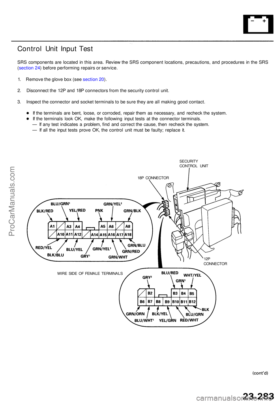
Control Uni t Inpu t Tes t
SRS component s ar e locate d in thi s area . Revie w th e SR S componen t locations , precautions , an d procedure s i n th e SR S
( sectio n 24 ) befor e performin g repair s o r service .
1 . Remov e th e glov e bo x (se e sectio n 20 ).
2 . Disconnec t th e 12 P an d 18 P connector s fro m th e securit y contro l unit .
3 . Inspec t th e connecto r an d socke t terminal s t o b e sur e the y ar e al l makin g goo d contact .
I f th e terminal s ar e bent , loose , o r corroded , repai r the m a s necessary , an d rechec k th e system .
I f th e terminal s loo k OK , mak e th e followin g inpu t test s a t th e connecto r terminals .
— If an y tes t indicate s a problem , fin d an d correc t th e cause , the n rechec k th e system .
— If al l th e inpu t test s prov e OK , th e contro l uni t mus t b e faulty ; replac e it .
SECURIT YCONTROL UNI T
18 P CONNECTO R
WIR E SID E O F FEMAL E TERMINAL S
12PCONNECTO R
ProCarManuals.com
Page 1732 of 1771
Security Alarm System
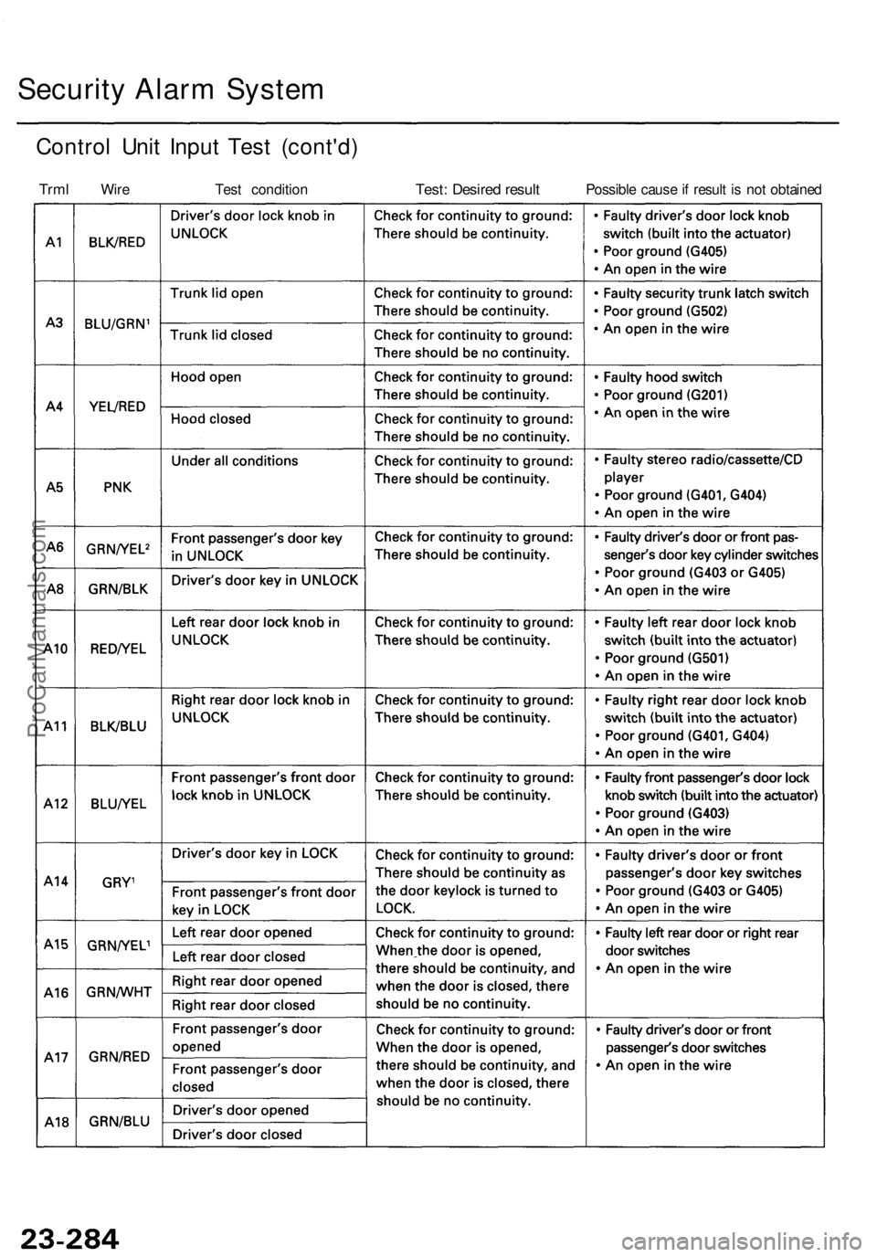
Control Unit Input Test (cont'd)
Trml
Wire
Test condition
Test: Desired result
Possible cause if result is not obtainedProCarManuals.com
Page 1733 of 1771
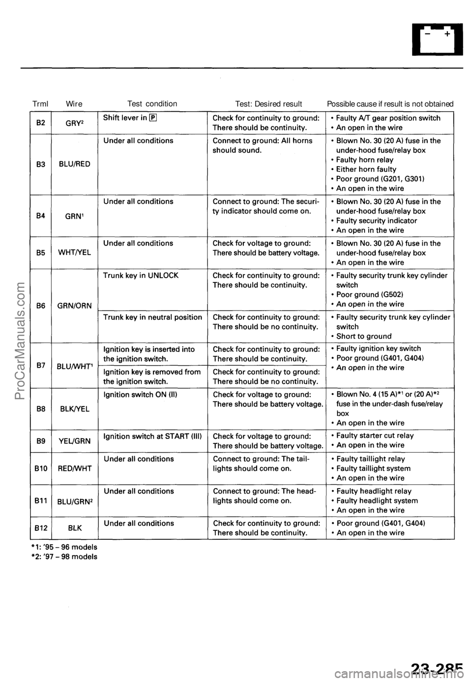
Trml Wire
Test condition
Test: Desired result
Possible cause if result is not obtainedProCarManuals.com
Page 1734 of 1771
Security Alar m Syste m
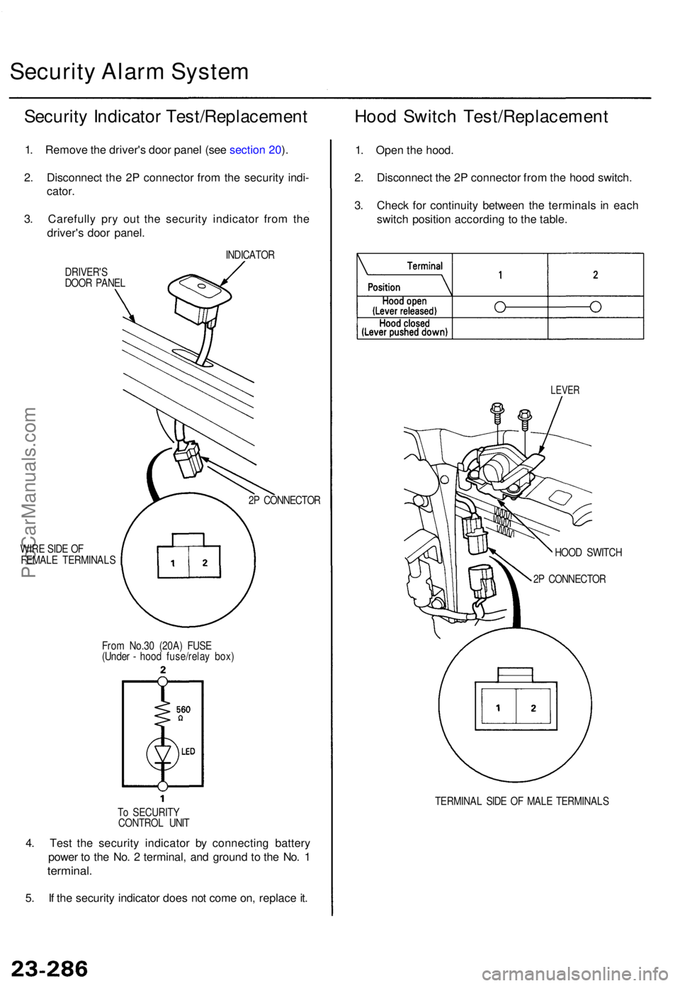
Securit y Indicato r Test/Replacemen t Hoo d Switc h Test/Replacemen t
1. Remov e th e driver' s doo r pane l (se e sectio n 20 ).
2 . Disconnec t th e 2 P connecto r fro m th e securit y indi -
cator .
3 . Carefull y pr y ou t th e securit y indicato r fro m th e
driver' s doo r panel .
INDICATO R
DRIVER' S
DOO R PANE L
WIR E SID E O F
FEMAL E TERMINAL S 2
P CONNECTO R
Fro m No.3 0 (20A ) FUS E
(Unde r - hoo d fuse/rela y box )
T o SECURIT Y
CONTRO L UNI T
4. Tes t th e securit y indicato r b y connectin g batter y
powe r t o th e No . 2 terminal , an d groun d t o th e No . 1
terminal .
5. I f th e securit y indicato r doe s no t com e on , replac e it . 1
. Ope n th e hood .
2 . Disconnec t th e 2 P connecto r fro m th e hoo d switch .
3 . Chec k fo r continuit y betwee n th e terminal s i n eac h
switc h positio n accordin g t o th e table .
LEVE R
HOOD SWITC H
2 P CONNECTO R
TERMINA L SID E O F MAL E TERMINAL S
ProCarManuals.com
Page 1735 of 1771
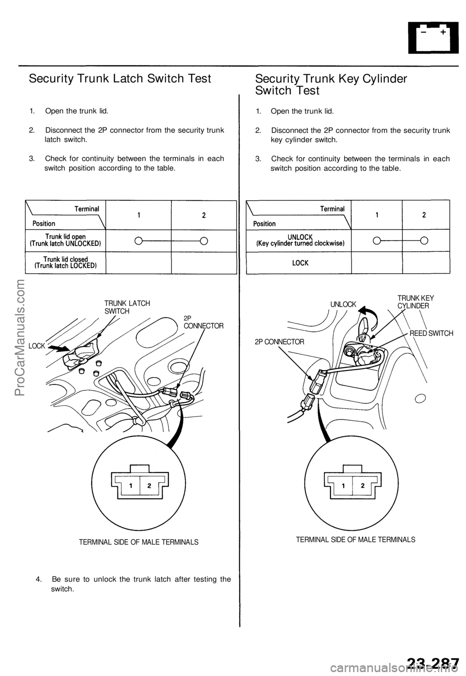
Security Trunk Latch Switch Test
1. Open the trunk lid.
2. Disconnect the 2P connector from the security trunk
latch switch.
3. Check for continuity between the terminals in each
switch position according to the table.
TRUNK LATCH
SWITCH
2P
CONNECTOR
LOCK
TERMINAL SIDE OF MALE TERMINALS
4. Be sure to unlock the trunk latch after testing the
switch.
Security Trunk Key Cylinder
Switch Test
1. Open the trunk lid.
2. Disconnect the 2P connector from the security trunk
key cylinder switch.
3. Check for continuity between the terminals in each
switch position according to the table.
UNLOCK
TRUNK KEY
CYLINDER
REED SWITCH
2P CONNECTOR
TERMINAL SIDE OF MALE TERMINALSProCarManuals.com
Page 1736 of 1771
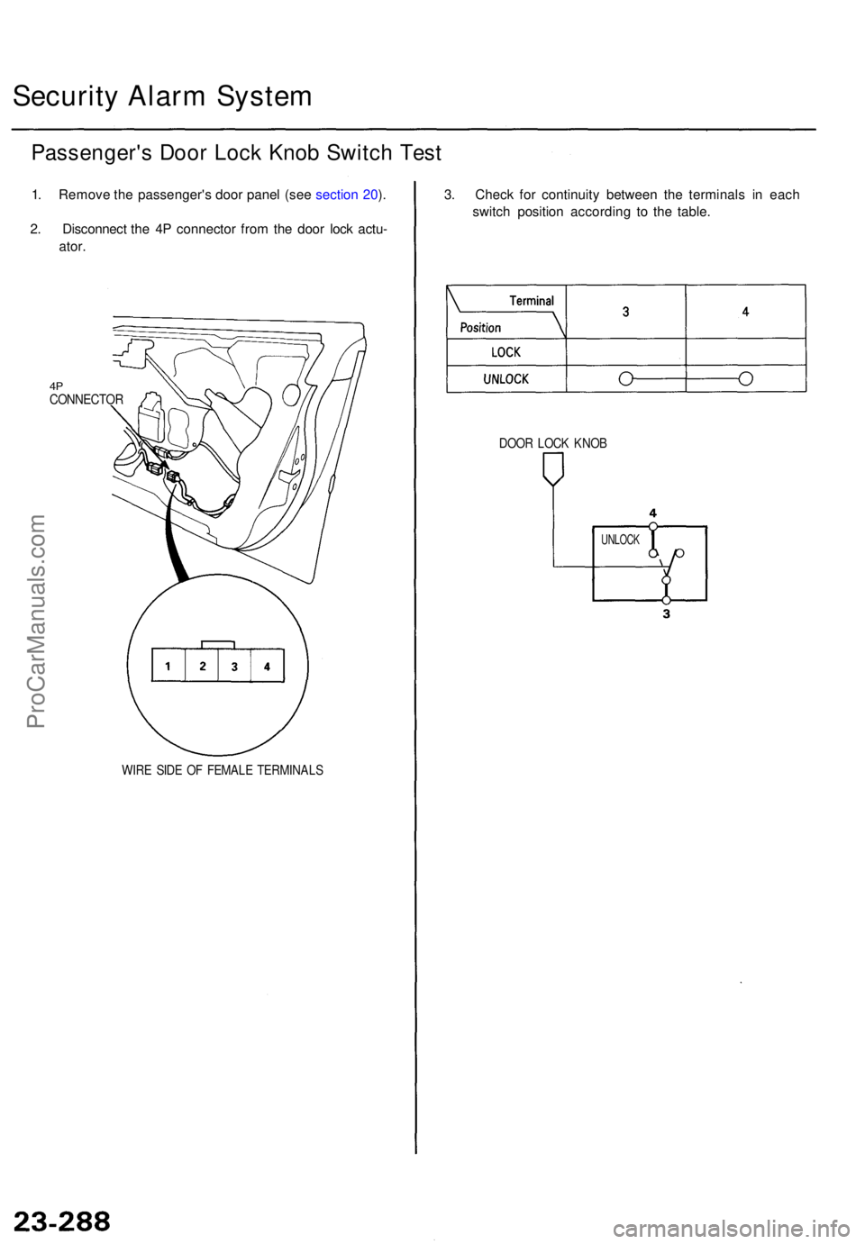
Security Alar m Syste m
Passenger' s Doo r Loc k Kno b Switc h Tes t
1. Remov e th e passenger' s doo r pane l (se e sectio n 20 ).
2 . Disconnec t th e 4 P connecto r fro m th e doo r loc k actu -
ator .
4PCONNECTO R
WIRE SID E O F FEMAL E TERMINAL S
3. Chec k fo r continuit y betwee n th e terminal s i n eac h
switc h positio n accordin g t o th e table .
DOOR LOC K KNO B
UNLOC K
ProCarManuals.com
Page 1737 of 1771
24-71
24-30
24-2 0
24-1 5
24-20
24-2 2
24-47
24-3 9
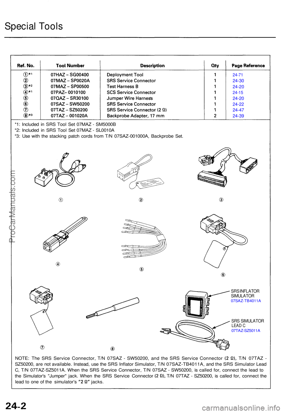
Specia l Tool s
SRS INFLATO R
SIMULATO R
07SAZ-TB4011 A
SRS SIMULATO RLEAD C07TAZ-SZ5011 A
NOTE: Th e SR S Servic e Connector , T/ N 07SA Z - SW50200 , an d th e SR S Servic e Connecto r T/ N 07TA Z -
SZ50200 , ar e no t available . Instead , us e th e SR S Inflato r Simulator , T/ N 07SAZ-TB4011A , an d th e SR S Simulato r Lea d
C , T/ N 07TA Z-SZ5011A . Whe n th e SR S Servic e Connector , T/ N 07SA Z - SW50200 , i s calle d for , connec t th e lea d t o
th e Simulator' s "Jumper " jack . Whe n th e SR S Servic e Connecto r T/ N 07TA Z - SZ50200 , i s calle d for , connec t th e
lea d t o on e o f th e simulator' s jacks .
*1
: Include d i n SR S Too l Se t 07MA Z - SM5000 B
*2 : Include d i n SR S Too l Se t 07MA Z - SL0010 A
*3 : Us e wit h th e stackin g patc h cord s fro m T/ N 07SA Z-001000A , Backprob e Set .
ProCarManuals.com
Page 1738 of 1771
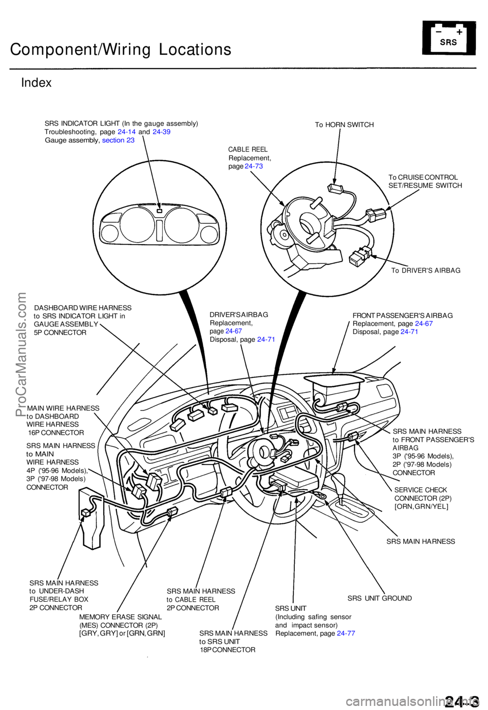
Component/Wiring Location s
Index
SRS INDICATO R LIGH T (I n th e gaug e assembly )
Troubleshooting , pag e 24-1 4 an d 24-3 9
Gaug e assembly , sectio n 2 3
To HOR N SWITC H
DASHBOAR D WIR E HARNES S
t o SR S INDICATO R LIGH T in
GAUG E ASSEMBL Y
5 P CONNECTO R
To DRIVER' S AIRBA G
FRONT PASSENGER' S AIRBA G
Replacement , pag e 24-6 7
Disposal , pag e 24-7 1
T
o CRUIS E CONTRO L
SET/RESUM E SWITC H
MAI N WIR E HARNES S
t o DASHBOAR D
WIR E HARNES S
16 P CONNECTO R
SR S MAI N HARNES S
to MAI NWIRE HARNES S
4 P ('95-9 6 Models) ,
3 P ('97-9 8 Models )
CONNECTO R SR
S MAI N HARNES S
t o FRON T PASSENGER' S
AIRBAG3P ('95-9 6 Models) ,
2 P ('97-9 8 Models )
CONNECTO R
SERVICE CHEC KCONNECTO R (2P )
[ORN , GRN/YEL ]
SR S MAI N HARNES S
SR S MAI N HARNES S
t o UNDER-DAS H
FUSE/RELAY BO X2P CONNECTO R
MEMOR Y ERAS E SIGNA L
(MES ) CONNECTO R (2P )
[GRY , GRY ] or [GRN , GRN ]SRS MAI N HARNES Sto SR S UNI T18P CONNECTO R SR
S UNI T GROUN D
SRS UNI T(Includin g safin g senso r
an d impac t sensor )
Replacement , pag e 24-7 7
CABL E REE LReplacement ,
pag e 24-7 3
DRIVER' S AIRBA G
Replacement ,
page 24-67Disposal , pag e 24-7 1
SR S MAI N HARNES S
to CABL E REE L2P CONNECTO R
ProCarManuals.com
Page 1739 of 1771
Description
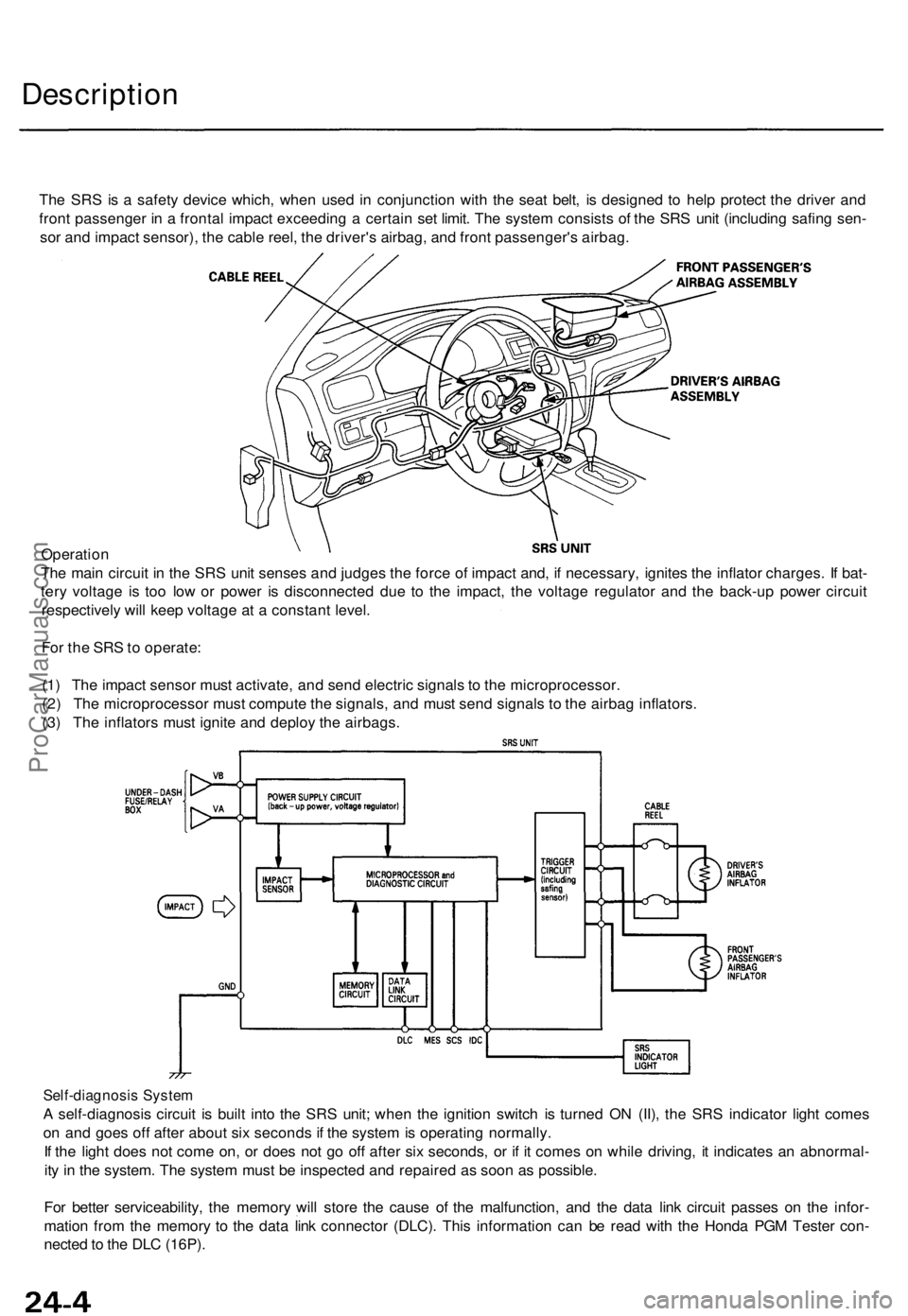
The SR S is a safet y devic e which , whe n use d i n conjunctio n wit h th e sea t belt , i s designe d t o hel p protec t th e drive r an d
fron t passenge r i n a fronta l impac t exceedin g a certai n se t limit . Th e syste m consist s o f th e SR S uni t (includin g safin g sen -
so r an d impac t sensor) , th e cabl e reel , th e driver' s airbag , an d fron t passenger' s airbag .
Operatio n
Th e mai n circui t i n th e SR S uni t sense s an d judge s th e forc e o f impac t and , i f necessary , ignite s th e inflato r charges . I f bat -
ter y voltag e i s to o lo w o r powe r i s disconnecte d du e t o th e impact , th e voltag e regulato r an d th e back-u p powe r circui t
respectivel y wil l kee p voltag e a t a constan t level .
Fo r th e SR S to operate :
(1 ) Th e impac t senso r mus t activate , an d sen d electri c signal s t o th e microprocessor .
(2 ) Th e microprocesso r mus t comput e th e signals , an d mus t sen d signal s t o th e airba g inflators .
(3 ) Th e inflator s mus t ignit e an d deplo y th e airbags .
Self-diagnosi s Syste m
A self-diagnosi s circui t i s buil t int o th e SR S unit ; whe n th e ignitio n switc h i s turne d O N (II) , th e SR S indicato r ligh t come s
o n an d goe s of f afte r abou t si x second s if th e syste m is operatin g normally .
I f th e ligh t doe s no t com e on , o r doe s no t g o of f afte r si x seconds , o r i f i t come s o n whil e driving , i t indicate s a n abnormal -
it y i n th e system . Th e syste m mus t b e inspecte d an d repaire d a s soo n a s possible .
Fo r bette r serviceability , th e memor y wil l stor e th e caus e o f th e malfunction , an d th e dat a lin k circui t passe s o n th e infor -
matio n fro m th e memor y t o th e dat a lin k connecto r (DLC) . Thi s informatio n ca n b e rea d wit h th e Hond a PG M Teste r con -
necte d to th e DL C (16P) .
ProCarManuals.com
Page 1740 of 1771
Precautions/Procedures
General Precaution s
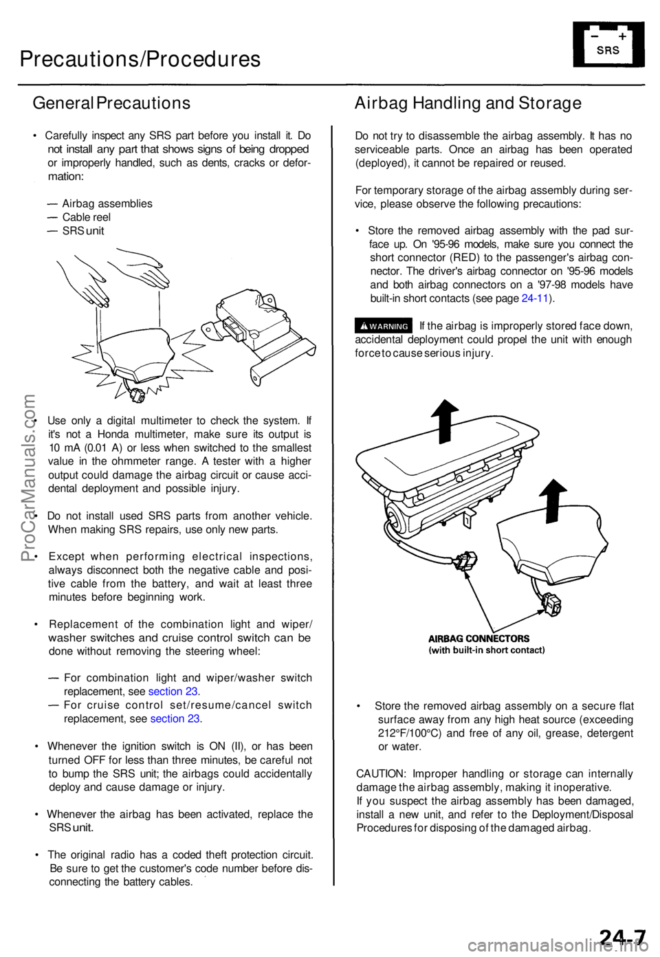
• Carefull y inspec t an y SR S par t befor e yo u instal l it . D o
not instal l an y par t tha t show s sign s o f bein g droppe d
or improperl y handled , suc h a s dents , crack s o r defor -
mation :
Airbag assemblie s
Cabl e ree l
SRS uni t
• Us e onl y a digita l multimete r t o chec k th e system . I f
it' s no t a Hond a multimeter , mak e sur e it s outpu t i s
1 0 m A (0.0 1 A ) o r les s whe n switche d t o th e smalles t
valu e i n th e ohmmete r range . A teste r wit h a highe r
outpu t coul d damag e th e airba g circui t o r caus e acci -
denta l deploymen t an d possibl e injury .
• D o no t instal l use d SR S part s fro m anothe r vehicle .
Whe n makin g SR S repairs , us e onl y ne w parts .
• Excep t whe n performin g electrica l inspections ,
alway s disconnec t bot h th e negativ e cabl e an d posi -
tiv e cabl e fro m th e battery , an d wai t a t leas t thre e
minute s befor e beginnin g work .
• Replacemen t of the combinatio n ligh t an d wiper /
washer switche s an d cruis e contro l switc h ca n b e
don e withou t removin g th e steerin g wheel :
Fo r combinatio n ligh t an d wiper/washe r switc h
replacement , se e sectio n 23 .
Fo r cruis e contro l set/resume/cance l switc h
replacement , se e sectio n 23 .
• Wheneve r th e ignitio n switc h i s O N (II) , o r ha s bee n
turne d OF F fo r les s tha n thre e minutes , b e carefu l no t
t o bum p th e SR S unit ; th e airbag s coul d accidentall y
deplo y an d caus e damag e o r injury .
• Wheneve r th e airba g ha s bee n activated , replac e th e
SR S unit .
• Th e origina l radi o ha s a code d thef t protectio n circuit .
B e sur e to ge t th e customer' s cod e numbe r befor e dis -
connectin g th e batter y cables .
Airbag Handlin g an d Storag e
Do no t tr y t o disassembl e th e airba g assembly . I t ha s n o
serviceabl e parts . Onc e a n airba g ha s bee n operate d
(deployed) , i t canno t b e repaire d o r reused .
Fo r temporar y storag e o f th e airba g assembl y durin g ser -
vice , pleas e observ e th e followin g precautions :
• Stor e th e remove d airba g assembl y wit h th e pa d sur -
fac e up . O n '95-9 6 models , mak e sur e yo u connec t th e
shor t connecto r (RED ) t o th e passenger' s airba g con -
nector . Th e driver' s airba g connecto r o n '95-9 6 model s
an d bot h airba g connector s o n a '97-9 8 model s hav e
built-i n shor t contact s (se e pag e 24-11 ).
I f th e airba g is improperl y store d fac e down ,
accidenta l deploymen t coul d prope l th e uni t wit h enoug h
forc e to caus e seriou s injury .
• Stor e th e remove d airba g assembl y o n a secur e fla t
surfac e awa y fro m an y hig h hea t sourc e (exceedin g
212°F/100°C ) an d fre e o f an y oil , grease , detergen t
o r water .
CAUTION : Imprope r handlin g o r storag e ca n internall y
damag e th e airba g assembly , makin g it inoperative .
I f yo u suspec t th e airba g assembl y ha s bee n damaged ,
instal l a ne w unit , an d refe r t o th e Deployment/Disposa l
Procedure s fo r disposin g o f th e damage d airbag .
ProCarManuals.com