ACURA TL 1995 Service Repair Manual
Manufacturer: ACURA, Model Year: 1995, Model line: TL, Model: ACURA TL 1995Pages: 1771, PDF Size: 62.49 MB
Page 181 of 1771
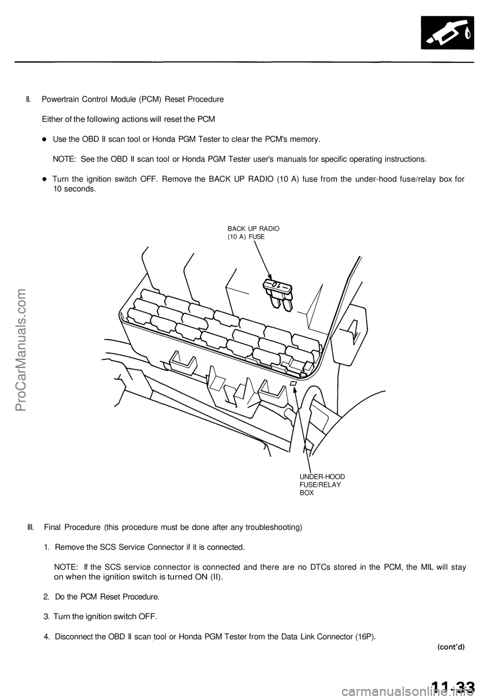
II. Powertrain Control Module (PCM) Reset Procedure
Either of the following actions will reset the PCM
Use the OBD II scan tool or Honda PGM Tester to clear the PCM's memory.
NOTE: See the OBD II scan tool or Honda PGM Tester user's manuals for specific operating instructions.
Turn the ignition switch OFF. Remove the BACK UP RADIO (10 A) fuse from the under-hood fuse/relay box for
10 seconds.
BACK UP RADIO
(10 A) FUSE
UNDER-HOOD
FUSE/RELAY
BOX
III. Final Procedure (this procedure must be done after any troubleshooting)
1. Remove the SCS Service Connector if it is connected.
NOTE: If the SCS service connector is connected and there are no DTCs stored in the PCM, the MIL will stay
on when the ignition switch is turned ON (II).
2. Do the PCM Reset Procedure.
3. Turn the ignition switch OFF.
4. Disconnect the OBD II scan tool or Honda PGM Tester from the Data Link Connector (16P).ProCarManuals.com
Page 182 of 1771
Troubleshooting
Troubleshootin g Procedure s (cont'd )
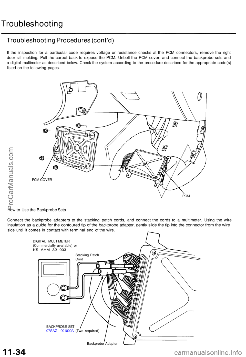
If th e inspectio n fo r a particula r cod e require s voltag e o r resistanc e check s a t th e PC M connectors , remov e th e righ t
doo r sil l molding . Pul l th e carpe t bac k t o expos e th e PCM . Unbol t th e PC M cover , an d connec t th e backprob e set s an d
a digita l multimete r a s describe d below . Chec k th e syste m accordin g t o th e procedur e describe d fo r th e appropriat e code(s )
liste d o n th e followin g pages .
PCM COVE R
PCM
Ho w to Us e th e Backprob e Set s
Connec t th e backprob e adapter s t o th e stackin g patc h cords , an d connec t th e cord s t o a multimeter . Usin g th e wir e
insulatio n a s a guid e fo r th e contoure d ti p o f th e backprob e adapter , gentl y slid e th e ti p int o th e connecto r fro m th e wir e
side unti l i t come s i n contac t wit h termina l en d o f th e wire .
DIGITA L MULTIMETE R
(Commerciall y available ) o r
KS - AH M - 32 - 00 3
BACKPROB E SE T
07SA Z - 001000 A (Tw o required )
Backprob e Adapter
Stackin
g Patc h
Cor d
ProCarManuals.com
Page 183 of 1771
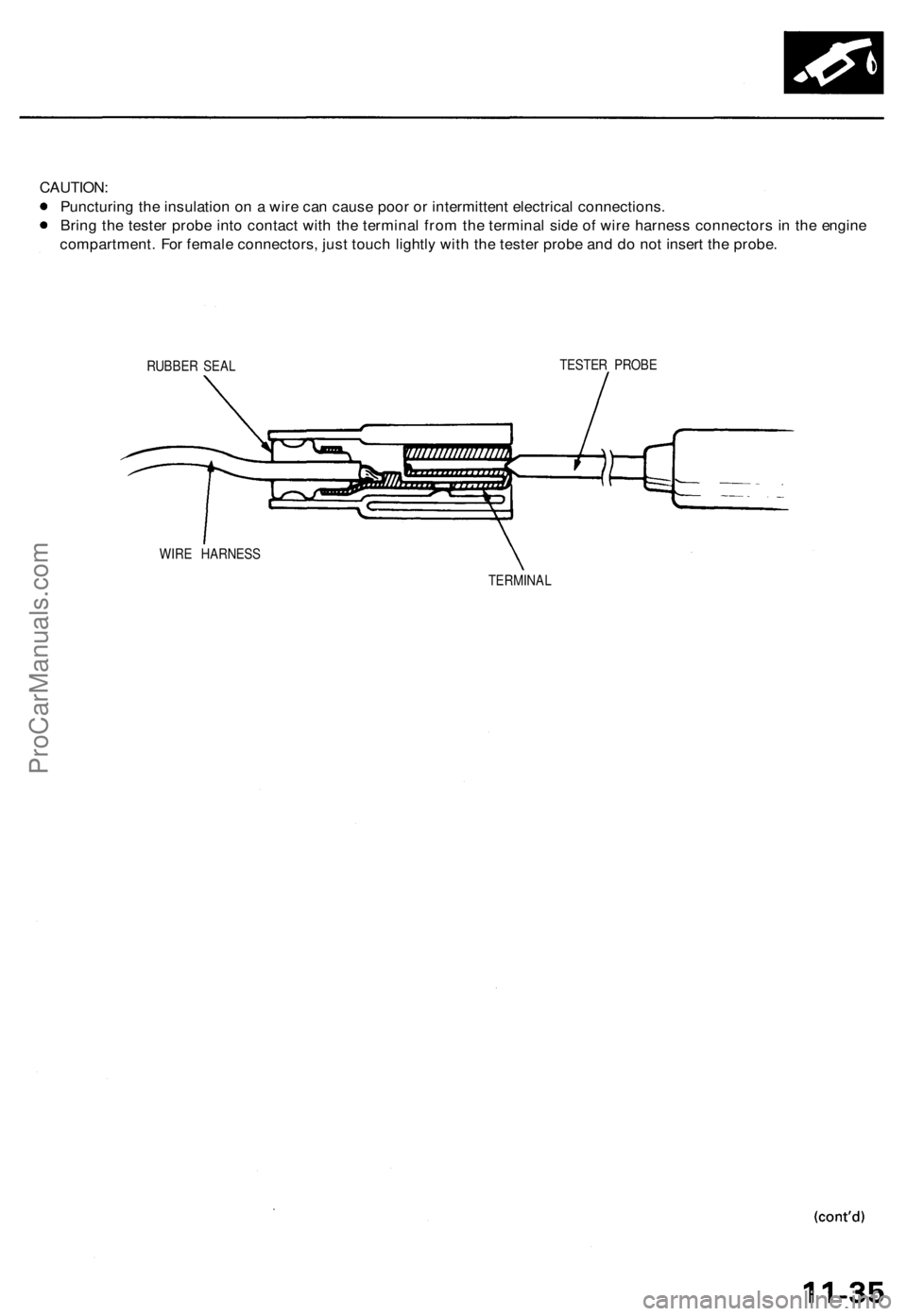
CAUTION:
Puncturing the insulation on a wire can cause poor or intermittent electrical connections.
Bring the tester probe into contact with the terminal from the terminal side of wire harness connectors in the engine
compartment. For female connectors, just touch lightly with the tester probe and do not insert the probe.
RUBBER SEAL
TESTER PROBE
WIRE HARNESS
TERMINALProCarManuals.com
Page 184 of 1771
Troubleshooting
Troubleshootin g Procedure s (cont'd )
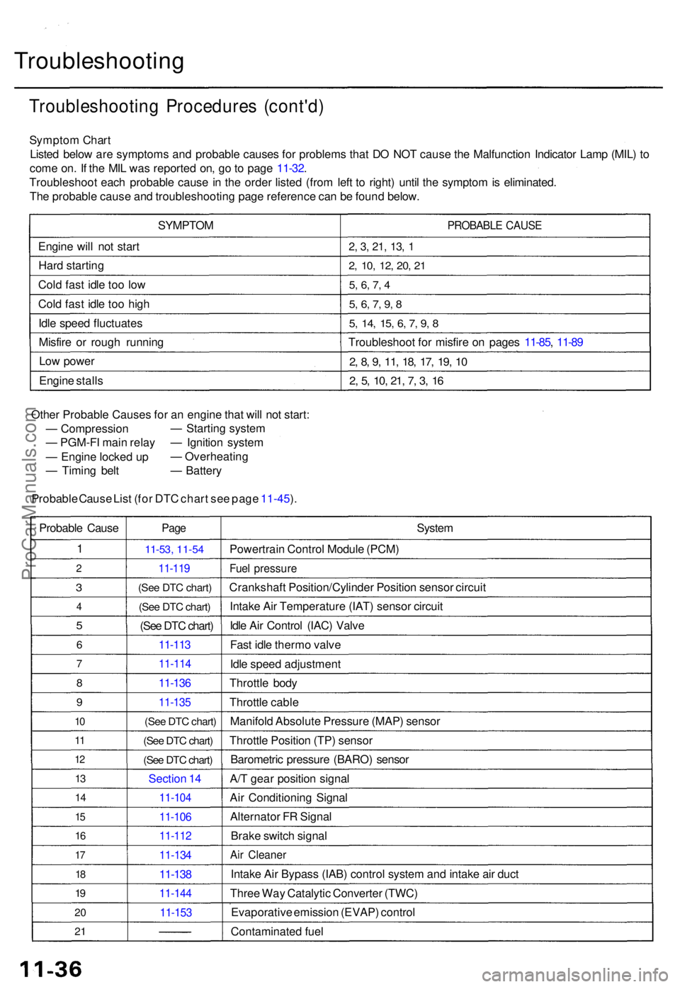
Sympto m Char t
Liste d belo w ar e symptom s an d probabl e cause s fo r problem s tha t D O NO T caus e th e Malfunctio n Indicato r Lam p (MIL ) t o
com e on . I f th e MI L wa s reporte d on , g o to pag e 11-32 .
Troubleshoo t eac h probabl e caus e in th e orde r liste d (fro m lef t t o right ) unti l th e sympto m is eliminated .
Th e probabl e caus e an d troubleshootin g pag e referenc e ca n b e foun d below .
SYMPTO M
Engin e wil l no t star t
Har d startin g
Col d fas t idl e to o lo w
Col d fas t idl e to o hig h
Idl e spee d fluctuate s
Misfir e o r roug h runnin g
Lo w powe r
Engin e stall s
PROBABL E CAUS E
2, 3 , 21 , 13 , 1
2 , 10 , 12 , 20 , 2 1
5, 6 , 7 , 4
5 , 6 , 7 , 9 , 8
5 , 14 , 15 , 6 , 7 , 9 , 8
Troubleshoo t fo r misfir e o n page s 11-85 , 11-8 9
2, 8 , 9 , 11 , 18 , 17 , 19 , 1 0
2, 5 , 10 , 21 , 7 , 3 , 1 6
Othe r Probabl e Cause s fo r a n engin e tha t wil l no t start :
— Compressio n
— PGM-F I mai n rela y
— Engin e locke d u p
— Timin g bel t
Probabl e Caus e Lis t (for DTC chart see page 11-45).
—
Startin g syste m
— Ignitio n syste m
— Overheatin g
— Batter y
Probabl e Caus e
1
2
3
4
5
6
7
8
9
10
1 1
1 2
13
1 4
15
1 6
17
18
19
2 0
2 1
Pag e
11-5 3, 11-54
11-11 9
(See DTC chart)
(See DTC chart)
(See DTC chart)
11-113
11-11 4
11-136
11-13 5
(See DTC chart)
(See DTC chart)
(See DTC chart)
Sectio n 1 4
11-10 4
11-106
11-112
11-13 4
11-138
11-14 4
11-153
System
Powertrai n Contro l Modul e (PCM )
Fuel pressur e
Crankshaf t Position/Cylinde r Positio n senso r circui t
Intak e Ai r Temperatur e (IAT ) senso r circui t
Idl e Ai r Contro l (IAC ) Valv e
Fas t idl e therm o valv e
Idl e spee d adjustmen t
Throttl e bod y
Throttl e cabl e
Manifol d Absolut e Pressur e (MAP ) senso r
Throttl e Positio n (TP ) senso r
Barometri c pressur e (BARO ) senso r
A/ T gea r positio n signa l
Ai r Conditionin g Signa l
Alternato r F R Signa l
Brak e switc h signa l
Air Cleane r
Intake Ai r Bypas s (IAB ) contro l syste m an d intak e ai r duc t
Thre e Wa y Catalyti c Converte r (TWC )
Evaporativ e emissio n (EVAP ) contro l
Contaminate d fue l
ProCarManuals.com
Page 185 of 1771
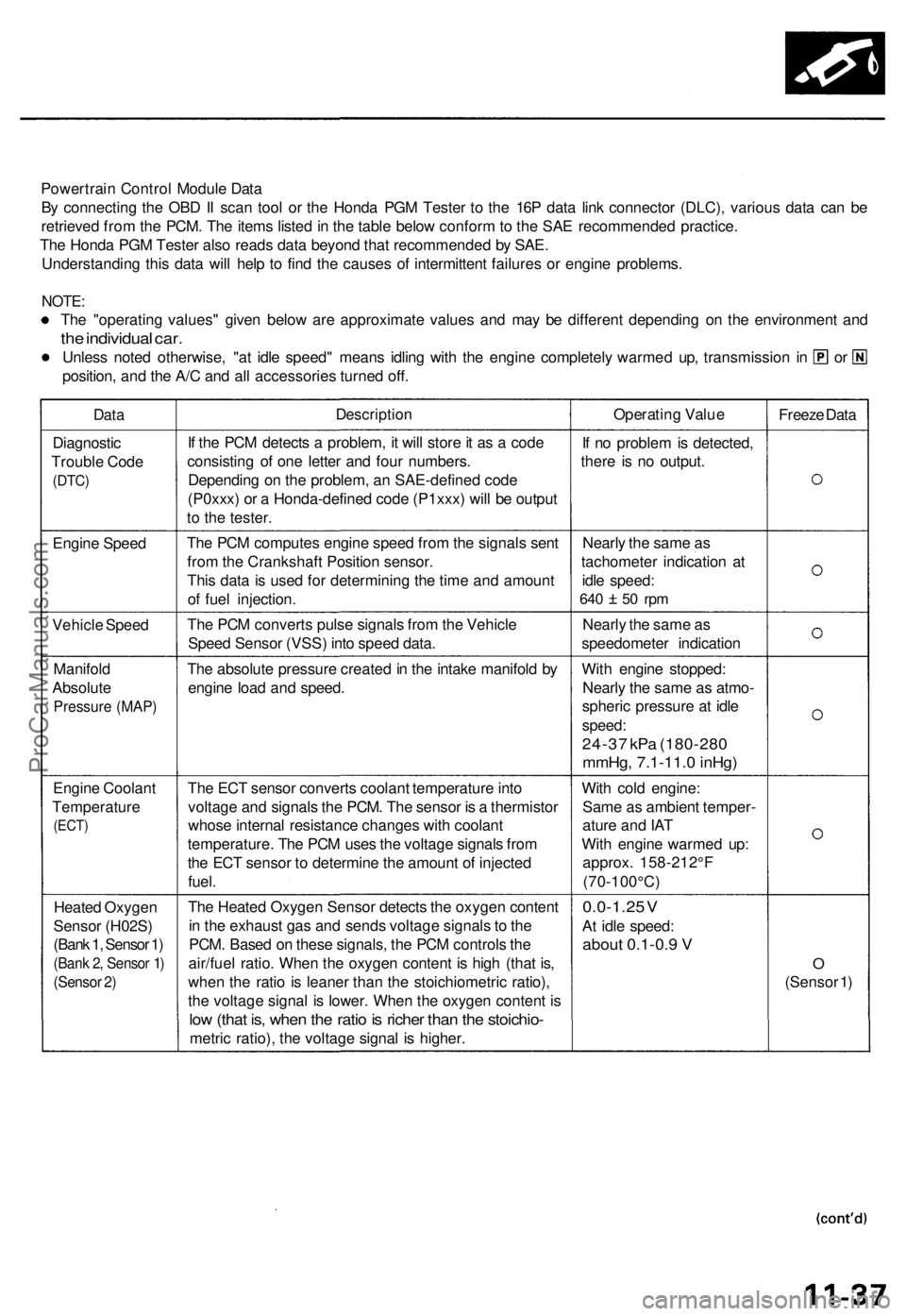
Powertrain Contro l Modul e Dat a
B y connectin g th e OB D II sca n too l o r th e Hond a PG M Teste r t o th e 16 P dat a lin k connecto r (DLC) , variou s dat a ca n b e
retrieve d fro m th e PCM . Th e item s liste d in th e tabl e belo w confor m to th e SA E recommende d practice .
Th e Hond a PG M Teste r als o read s dat a beyon d tha t recommende d b y SAE .
Understandin g thi s dat a wil l hel p t o fin d th e cause s o f intermitten t failure s o r engin e problems .
NOTE:
The "operatin g values " give n belo w ar e approximat e value s an d ma y b e differen t dependin g o n th e environmen t an d
the individua l car .
Unles s note d otherwise , "a t idl e speed " mean s idlin g wit h th e engine completel y warme d up , transmissio n i n o r
position , an d th e A/ C an d al l accessorie s turne d off .
Dat aDescriptio nOperating Valu e
Freeze Dat a
Diagnosti c
Troubl e Cod e
(DTC )
If th e PC M detect s a problem , i t wil l stor e it a s a cod e
consistin g o f on e lette r an d fou r numbers .
Dependin g o n th e problem , a n SAE-define d cod e
(P0xxx ) o r a Honda-define d cod e (P1xxx ) wil l b e outpu t
t o th e tester . I
f n o proble m is detected ,
ther e i s n o output .
Engin e Spee d Th
e PC M compute s engin e spee d fro m th e signal s sen t
fro m th e Crankshaf t Positio n sensor .
Thi s dat a is use d fo r determinin g th e tim e an d amoun t
o f fue l injection . Nearl
y th e sam e a s
tachomete r indicatio n a t
idl e speed :
640 5 0 rp m
Vehicl e Spee d Th
e PC M convert s puls e signal s fro m th e Vehicl e
Spee d Senso r (VSS ) int o spee d data . Nearl
y th e sam e a s
speedomete r indicatio n
Manifol d
Absolut e
Pressur e (MAP )
The absolut e pressur e create d in th e intak e manifol d b y
engin e loa d an d speed . Wit
h engin e stopped :
Nearl y th e sam e a s atmo -
spheri c pressur e a t idl e
speed :
24-37 kP a (180-28 0
mmHg, 7.1-11. 0 inHg )
Engin e Coolan t
Temperatur e
(ECT)
The EC T senso r convert s coolan t temperatur e int o
voltag e an d signal s th e PCM . Th e senso r i s a thermisto r
whos e interna l resistanc e change s wit h coolan t
temperature . Th e PC M use s th e voltag e signal s fro m
th e EC T senso r t o determin e th e amoun t o f injecte d
fuel . Wit
h col d engine :
Sam e a s ambien t temper -
atur e an d IA T
Wit h engin e warme d up :
approx . 158-212° F
(70-100°C )
Heate d Oxyge n
Senso r (H02S )
(Bank 1, Sensor 1)
(Ban k 2 , Senso r 1 )
(Senso r 2 )
Th e Heate d Oxyge n Senso r detect s th e oxyge n conten t
i n th e exhaus t ga s an d send s voltag e signal s to th e
PCM . Base d o n thes e signals , th e PC M control s th e
air/fue l ratio . Whe n th e oxyge n conten t i s hig h (tha t is ,
whe n th e rati o is leane r tha n th e stoichiometri c ratio) ,
th e voltag e signa l i s lower . Whe n th e oxyge n conten t i s
lo w (tha t is , whe n th e rati o is riche r tha n th e stoichio -
metric ratio) , th e voltag e signa l i s higher .
0.0-1.2 5 V
A t idl e speed :
about 0.1-0. 9 V
O
(Senso r 1 )
ProCarManuals.com
Page 186 of 1771
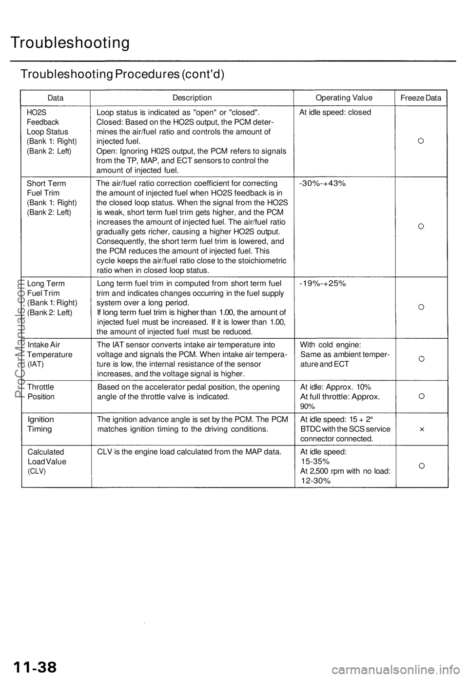
Troubleshooting
Troubleshooting Procedure s (cont'd )
DataDescriptio nOperating Valu e
Freeze Dat a
HO2 S
Feedbac k
Loop Statu s
(Bank 1 : Right )
(Bank 2 : Left )
Loop statu s i s indicate d a s "open " o r "closed" .
Closed: Based o n th e HO2 S output , th e PC M deter -
mine s th e air/fue l rati o an d control s th e amoun t o f
injecte d fuel .
Open : Ignorin g H02 S output , th e PC M refer s t o signal s
fro m th e TP , MAP , an d EC T sensor s to contro l th e
amoun t o f injecte d fuel . A
t idl e speed : close d
Shor t Ter m
Fue l Tri m
(Ban k 1 : Right )
(Bank 2 : Left )
The air/fue l rati o correctio n coefficien t fo r correctin g
th e amoun t o f injecte d fue l whe n HO2 S feedbac k is in
th e close d loo p status . Whe n th e signa l fro m th e HO2 S
i s weak , shor t ter m fue l tri m get s higher , an d th e PC M
increase s th e amoun t o f injecte d fuel . Th e air/fue l rati o
graduall y get s richer , causin g a highe r HO2 S output .
Consequently , th e shor t ter m fue l tri m is lowered , an d
th e PC M reduce s th e amoun t o f injecte d fuel . Thi s
cycl e keep s th e air/fue l rati o close to th e stoichiometri c
rati o whe n in close d loo p status .-30%-+43 %
Long Ter m
Fue l Tri m
(Ban k 1 : Right )
(Ban k 2 : Left ) Lon
g ter m fue l tri m in compute d fro m shor t ter m fue l
tri m an d indicate s change s occurrin g in th e fue l suppl y
syste m ove r a lon g period .
If lon g ter m fue l tri m is highe r tha n 1.00 , th e amoun t o f
injecte d fue l mus t b e increased . I f i t i s lowe r tha n 1.00 ,
th e amoun t o f injecte d fue l mus t b e reduced .
-19%-+25 %
Intake Ai r
Temperatur e
(IAT)
The IA T senso r convert s intak e ai r temperatur e int o
voltag e an d signal s th e PCM . Whe n intak e ai r tempera -
tur e is low , th e interna l resistanc e o f th e senso r
increases , an d th e voltag e signa l i s higher . Wit
h col d engine :
Sam e a s ambien t temper -
atur e an d EC T
Throttl e
Positio n Base
d o n th e accelerato r peda l position , th e openin g
angl e o f th e throttl e valv e is indicated . A
t idle : Approx . 10 %
At ful l throttle : Approx .
90%
Ignitio n
Timing
The ignitio n advanc e angl e is se t b y th e PCM . Th e PC M
matche s ignitio n timin g t o th e drivin g conditions .A
t idl e speed : 1 5 + 2°
BTD C wit h th e SC S servic e
connecto r connected .
Calculated
Load Valu e
(CLV )
CLV is th e engin e loa d calculate d fro m th e MA P data . At idl e speed :
15-35 %
A t 2,50 0 rp m wit h n o load :
12-30 %
ProCarManuals.com
Page 187 of 1771
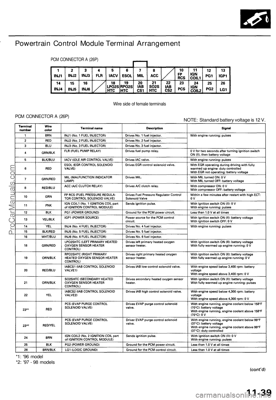
Powertrain Contro l Modul e Termina l Arrangemen t
PCM CONNECTO R A (26P )
Wire sid e o f femal e terminal s
PCM CONNECTO R A (26P )NOTE : Standar d batter y voltag e is 1 2 V .
*1 : '9 6 mode l
*2 : '9 7 - 9 8 model s
ProCarManuals.com
Page 188 of 1771
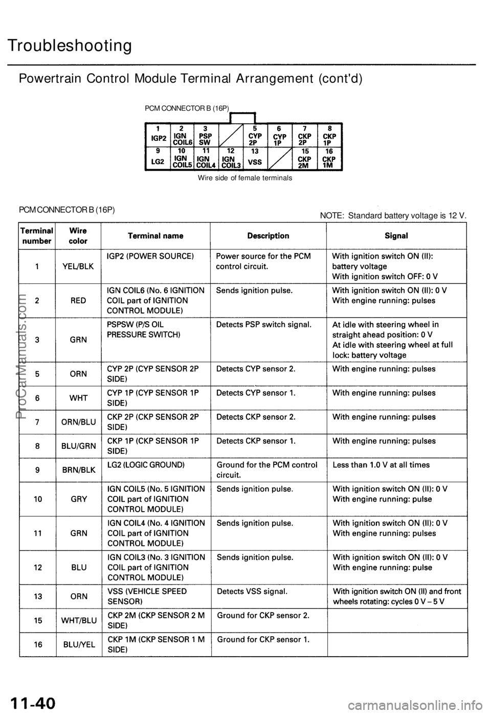
Troubleshooting
Powertrain Control Module Terminal Arrangement (cont'd)
PCM CONNECTOR B (16P)
Wire side of female terminals
PCM CONNECTOR B (16P)
NOTE: Standard battery voltage is 12 V.ProCarManuals.com
Page 189 of 1771
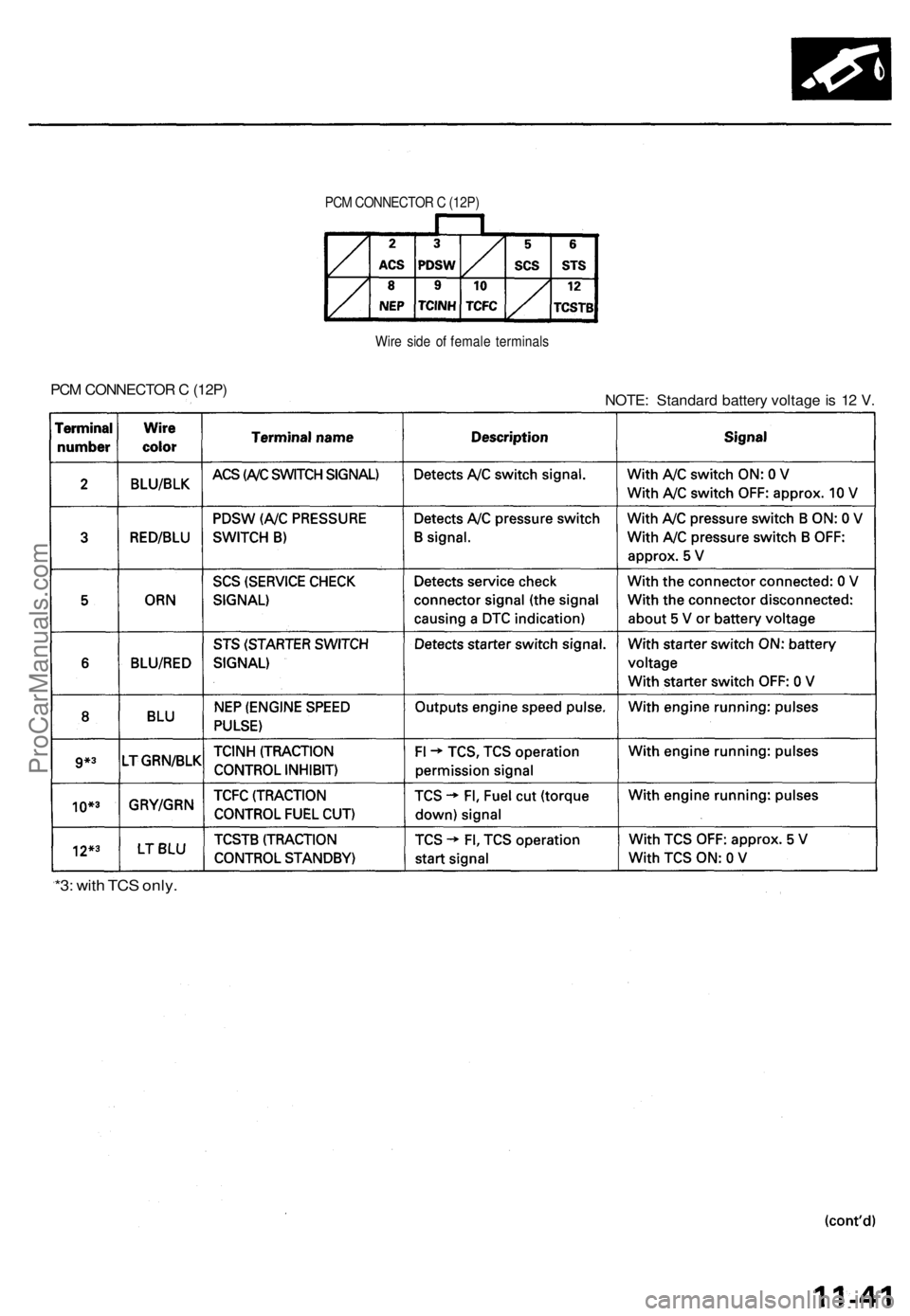
PCM CONNECTO R C (12P )
Wir e sid e o f femal e terminal s
PCM CONNECTO R C (12P )
NOTE: Standar d batter y voltag e is 1 2 V .
*3: wit h TC S only .
ProCarManuals.com
Page 190 of 1771
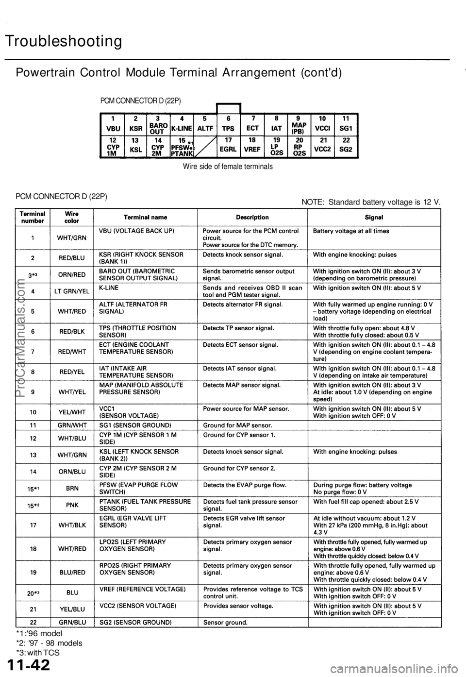
Troubleshooting
Powertrain Control Module Terminal Arrangement (cont'd)
PCM CONNECTOR D (22P)
Wire side of female terminals
PCM CONNECTOR D (22P)
NOTE: Standard battery voltage is 12 V.
*1:'96 model
*2: '97 - 98 models
*3: with TCSProCarManuals.com