ACURA TL 1995 Service Repair Manual
Manufacturer: ACURA, Model Year: 1995, Model line: TL, Model: ACURA TL 1995Pages: 1771, PDF Size: 62.49 MB
Page 311 of 1771
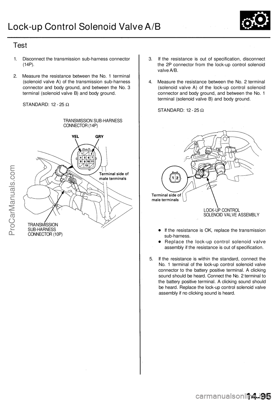
Lock-up Contro l Solenoi d Valv e A/ B
Tes t
STANDARD : 1 2 - 2 5 W
1
. Disconnec t th e transmissio n sub-harnes s connecto r
(14P).
2. Measur e th e resistanc e betwee n th e No . 1 termina l
(solenoi d valv e A ) o f th e transmissio n sub-harnes s
connecto r an d bod y ground , an d betwee n th e No . 3
termina l (solenoi d valv e B ) an d bod y ground .
TRANSMISSIO N SUB-HARNES SCONNECTOR (14P )
TRANSMISSIO NSUB-HARNESSCONNECTOR (10P )
5. I f th e resistanc e i s withi n th e standard , connec t th e
No . 1 termina l o f th e lock-u p contro l solenoi d valv e
connecto r t o th e batter y positiv e terminal . A clickin g
soun d shoul d b e heard . Connec t th e No . 2 termina l t o
th e batter y positiv e terminal . A clickin g soun d shoul d
b e heard . Replac e th e lock-u p contro l solenoi d valv e
assembl y if n o clickin g soun d is heard .
I
f th e resistanc e i s OK , replac e th e transmissio n
sub-harness .
Replace th e lock-u p contro l solenoi d valv e
assembl y if th e resistanc e is ou t o f specification .
LOCK-UP CONTRO LSOLENOID VALV E ASSEMBL Y
3. I f th e resistanc e i s ou t o f specification , disconnec t
th e 2 P connecto r fro m th e lock-u p contro l solenoi d
valv e A/B .
4 . Measur e th e resistanc e betwee n th e No . 2 termina l
(solenoi d valv e A ) o f th e lock-u p contro l solenoi d
connecto r an d bod y ground , an d betwee n th e No . 1
termina l (solenoi d valv e B ) an d bod y ground .
STANDARD : 1 2 - 2 5 W
ProCarManuals.com
Page 312 of 1771
Lock-up Contro l Solenoi d Valve A/B
Replacemen t
NOTE: Lock-u p contro l solenoi d valv e A an d B mus t b e
replace d a s a n assembly .
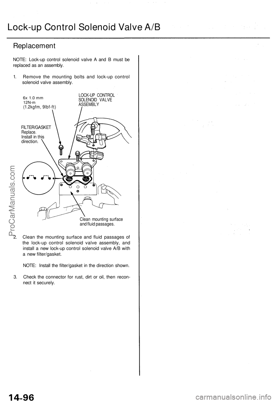
1 . Remov e th e mountin g bolt s an d lock-u p contro l
solenoi d valv e assembly .
2 . Clea n th e mountin g surfac e an d flui d passage s o f
th e lock-u p contro l solenoi d valv e assembly , an d
instal l a ne w lock-u p contro l solenoi d valv e A/ B wit h
a ne w filter/gasket .
NOTE : Instal l th e filter/gaske t i n th e directio n shown .
3 . Chec k th e connecto r fo r rust , dir t o r oil , the n recon -
nec t i t securely .
Clean mountin g surfac eand flui d passages .
FILTER/GASKE TReplace.Install i n thi sdirection .
6x 1. 0 m m12N- m(1.2kgfm , 9lbf-ft )
LOCK-U P CONTRO L
SOLENOI D VALV E
ASSEMBL Y
ProCarManuals.com
Page 313 of 1771
Shift Contro l Solenoi d
Test
1. Disconnec t th e transmissio n sub-harnes s connecto r
(14P).
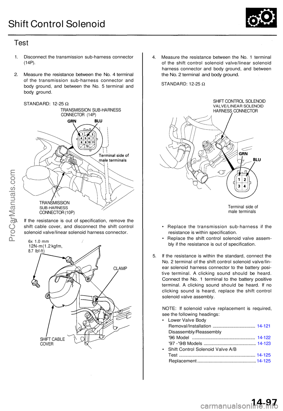
2. Measur e th e resistanc e betwee n th e No . 4 termina l
of th e transmissio n sub-harnes s connecto r an d
bod y ground , an d betwee n th e No . 5 termina l an d
bod y ground .
TRANSMISSIO NSUB-HARNESSCONNECTOR (10P )
3. I f th e resistanc e i s ou t o f specification , remov e th e
shif t cabl e cover , an d disconnec t th e shif t contro l
solenoi d valve/linea r solenoi d harnes s connector .
6x 1. 0 m m12N-m(1. 2 kgfm ,8.7 Ibf-ft )
CLAM P
SHIFT CABL ECOVER
4. Measur e th e resistanc e betwee n th e No . 1 termina l
o f th e shif t contro l solenoi d valve/linea r solenoi d
harnes s connecto r an d bod y ground , an d betwee n
the No . 2 termina l an d bod y ground .
SHIFT CONTRO L SOLENOI DVALVE/LINEA R SOLENOI DHARNESS CONNECTO R
Terminal sid e o f
mal e terminal s
• Replac e th e transmissio n sub-harnes s i f th e
resistanc e is withi n specification .
• Replac e th e shif t contro l solenoi d valv e assem -
bl y i f th e resistanc e is ou t o f specification .
5 . I f th e resistanc e i s withi n th e standard , connec t th e
No . 2 termina l o f th e shif t contro l solenoi d valve/lin -
ea r solenoi d harnes s connecto r t o th e batter y posi -
tiv e terminal . A clickin g soun d shoul d b e heard .
Connec t th e No . 1 termina l t o th e batter y positiv e
terminal . A clickin g soun d shoul d b e heard . I f n o
clickin g soun d i s heard , replac e th e shif t contro l
solenoi d valv e assembly .
NOTE : I f solenoi d valv e replacemen t i s required ,
se e th e followin g headings :
• Lowe r Valv e Bod y
Removal/Installatio n
................................... 14-12 1
Disassembly/Reassembl y
'96 Mode l ................................................... . 14-12 2
'97 -'9 8 Model s ......................................... . 14-12 3
• Shif t Contro l Solenoi d Valv e A/ B
Tes t
............................................................. . 14-12 5
Replacemen t
.............................................. . 14-12 5
STANDARD
: 1 2-2 5 W
TRANSMISSIO N SUB-HARNES SCONNECTOR (14P )
STANDARD: 12-25 W
ProCarManuals.com
Page 314 of 1771
Linear Solenoi d
Test
1. Disconnec t th e transmissio n sub-harnes s connecto r
(HP).
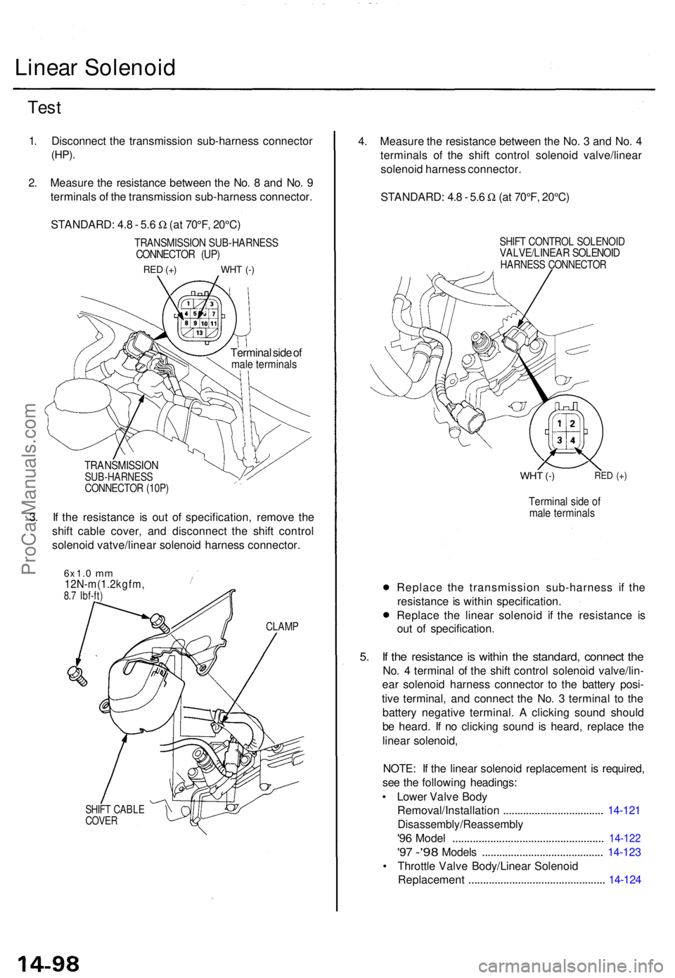
2. Measur e th e resistanc e betwee n th e No . 8 an d No . 9
terminal s o f th e transmissio n sub-harnes s connector .
STANDARD : 4. 8 - 5. 6 W (a t 70°F , 20°C )
TRANSMISSIO N SUB-HARNES SCONNECTOR (UP )
RED (+ ) WH T (- )
Termina l sid e o fmal e terminal s
TRANSMISSIO NSUB-HARNESSCONNECTOR (10P )
3. I f th e resistanc e i s ou t o f specification , remov e th e
shif t cabl e cover , an d disconnec t th e shif t contro l
solenoi d vatve/linea r solenoi d harnes s connector .
6x1.0 mm12N-m(1.2kgfm ,8.7 Ibf-ft )
CLAM P
SHIFT CABL ECOVER
4. Measur e th e resistanc e betwee n th e No . 3 an d No . 4
terminal s o f th e shif t contro l solenoi d valve/linea r
solenoi d harnes s connector .
STANDARD : 4. 8 - 5. 6 W (a t 70°F , 20°C )
SHIFT CONTRO L SOLENOI DVALVE/LINEA R SOLENOI DHARNESS CONNECTO R
WHT (- )RE D (+ )
Termina l sid e o fmal e terminal s
• Replac
e th e transmissio n sub-harnes s i f th e
resistanc e is withi n specification .
• Replac
e th e linea r solenoi d i f th e resistanc e i s
ou t o f specification .
5. I f th e resistanc e is withi n th e standard , connec t th e
No . 4 termina l o f th e shif t contro l solenoi d valve/lin -
ea r solenoi d harnes s connecto r t o th e batter y posi -
tiv e terminal , an d connec t th e No . 3 termina l t o th e
batter y negativ e terminal . A clickin g soun d shoul d
b e heard . I f n o clickin g soun d i s heard , replac e th e
linea r solenoid ,
NOTE : I f th e linea r solenoi d replacemen t i s required ,
se e th e followin g headings :
• Lowe r Valv e Bod y
Removal/Installatio n
................................... 14-12 1
Disassembly/Reassembl y
'96 Mode l ................................................... . 14-12 2
'97 -'9 8 Model s ......................................... . 14-12 3
• Throttl e Valv e Body/Linea r Solenoi d
Replacemen t
.............................................. . 14-12 4
ProCarManuals.com
Page 315 of 1771
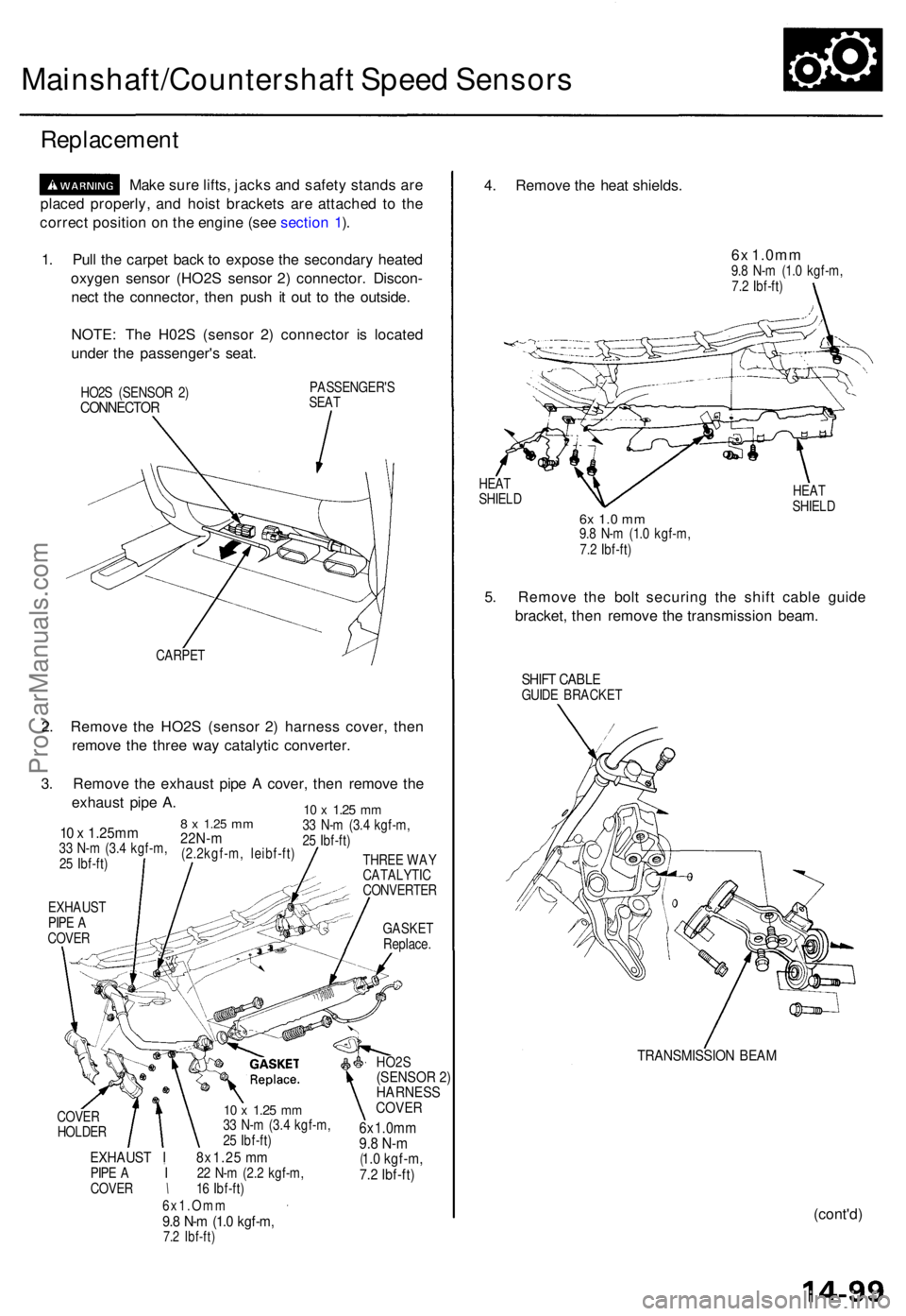
Mainshaft/Countershaft Spee d Sensor s
Replacemen t
Make sur e lifts , jack s an d safet y stand s ar e
place d properly , an d hois t bracket s ar e attache d t o th e
correc t positio n o n th e engin e (se e sectio n 1 ).
1 . Pul l th e carpe t bac k t o expos e th e secondar y heate d
oxyge n senso r (HO2 S senso r 2 ) connector . Discon -
nec t th e connector , the n pus h i t ou t t o th e outside .
NOTE : Th e H02 S (senso r 2 ) connecto r i s locate d
unde r th e passenger' s seat .
HO2S (SENSO R 2 )CONNECTO R
PASSENGER' S
SEA T
CARPE T
2. Remov e th e HO2 S (senso r 2 ) harnes s cover , the n
remov e th e thre e wa y catalyti c converter .
3 . Remov e th e exhaus t pip e A cover , the n remov e th e
exhaus t pip e A .
8 x 1.2 5 mm22N- m(2.2kgf-m , leibf-ft )
10 x 1.25m m33 N- m (3. 4 kgf-m ,
2 5 Ibf-ft )
10 x 1.2 5 mm33 N- m (3. 4 kgf-m ,
2 5 Ibf-ft )
THRE E WA Y
CATALYTI C
CONVERTE R
EXHAUS T
PIP E A
COVE R GASKE
T
Replace .
COVE R
HOLDE R
10 x 1.2 5 mm33 N- m (3. 4 kgf-m ,
2 5 Ibf-ft )
EXHAUS T I 8x1.2 5 m mPIP E A I 22 N- m (2. 2 kgf-m ,
COVE R \ 16 Ibf-ft )
6x1.Om m
9.8 N- m (1. 0 kgf-m ,7.2 Ibf-ft )
HO2S(SENSOR 2)
HARNESS
COVER
6 x 1. 0 m m9.8 N-m(1.0 kgf-m,
7.2 Ibf-ft)
4 . Remov e th e hea t shields .
6x 1.0m m9.8 N- m (1. 0 kgf-m ,
7. 2 Ibf-ft )
HEA T
SHIEL D HEA
T
SHIEL D
6x 1. 0 m m9.8 N- m (1. 0 kgf-m ,
7. 2 Ibf-ft )
5. Remov e th e bol t securin g th e shif t cabl e guid e
bracket , the n remov e th e transmissio n beam .
SHIFT CABL EGUIDE BRACKE T
TRANSMISSIO N BEA M
(cont'd )
ProCarManuals.com
Page 316 of 1771
Mainshaft/Countershaft Speed Sensors
Replacement (cont'd)
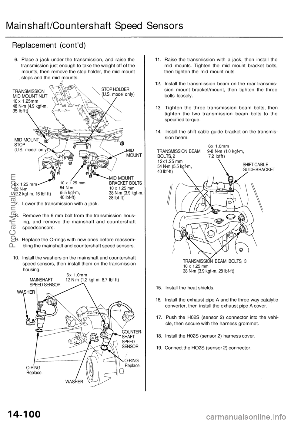
6. Place a jack under the transmission, and raise the
transmission just enough to take the weight off of the
mounts, then remove the stop holder, the mid mount
stops and the mid mounts.
TRANSMISSION
MID MOUNT NUT
10 x 1.25mm
48 N-m (4.9 kgf-m,
35 Ibfft
STOP HOLDER
(U.S. model only)
MID MOUNT
STOP
(U.S. model onlyf
10 x
1.25
mm
54 N-m
(5.5 kgf-m,
40 Ibf-ft)
7. Lower the transmission with a jack.
8x
1.25
mm
22 N-m
(2.2 kgf-m, 16 Ibf-ft)
MID
MOUNT
MID MOUNT
BRACKET BOLTS
10 x
1.25
mm
38 N-m (3.9 kgf-m,
28 Ibf-ft)
8. Remove the 6 mm bolt from the transmission hous-
ing, and remove the mainshaft and countershaft
speed sensors.
9. Replace the O-rings with new ones before reassem-
bling the mainshaft and countershaft speed sensors.
10. Install the washers on the mainshaft and countershaft
speed sensors, then install them on the transmission
housing.
6x
1.0mm
MAINSHAFT 12 N-m (1.2 kgf-m, 8.7 Ibf-ft)
SPEED SENSOR
WASHER
O-RING
Replace.
COUNTER-
SHAFT
SPEED
SENSOR
O-RING
Replace.
WASHER
11. Raise the transmission with a jack, then install the
mid mounts. Tighten the mid mount bracket bolts,
then tighten the mid mount nuts.
12. Install the transmission beam on the rear transmis-
sion mount bracket/mount, then tighten the three
bolts loosely.
13. Tighten the three transmission beam bolts, then
tighten the two transmission beam bolts to the
specified torque.
14. Install the shift cable guide bracket on the transmis-
sion beam.
6x
1.0mm
TRANSMISSION BEAM 9-8 N-m (1.0 kgf-m,
BOLTS, 2 7.2 Ibfft)
12x1.25 mm
54 N-m (5.5 kgf-m,
40 Ibf-ft)
SHIFT CABLE
GUIDE BRACKET
TRANSMISSION BEAM BOLTS, 3
10 x
1.25
mm
38 N-m (3.9 kgf-m, 28 Ibf-ft)
15. Install the heat shields.
16. Install the exhaust pipe A and the three way catalytic
converter, then install the exhaust pipe A cover.
17. Push the H02S (sensor 2) connector into the vehi-
cle, then secure with the harness grommet.
18. Install the H02S (sensor 2) harness cover.
19. Connect the HO2S (sensor 2) connector.ProCarManuals.com
Page 317 of 1771
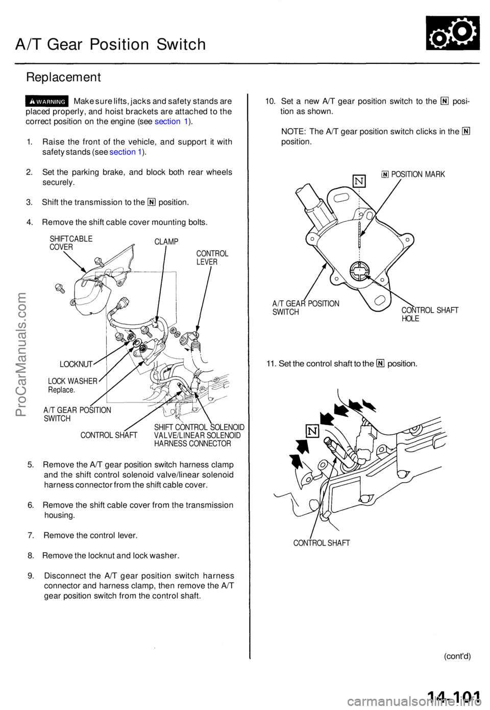
A/T Gea r Positio n Switc h
Replacemen t
Make sur e lifts , jack s an d safet y stand s ar e
place d properly , an d hois t bracket s ar e attache d to th e
correc t positio n o n th e engin e (se e sectio n 1 ).
1 . Rais e th e fron t o f th e vehicle , an d suppor t i t wit h
safet y stand s (se e sectio n 1 ).
2 . Se t th e parkin g brake , an d bloc k bot h rea r wheel s
securely .
3. Shif t th e transmissio n t o th e position .
4 . Remov e th e shif t cabl e cove r mountin g bolts .
CLAM P
SHIF
T CABL ECOVERCONTRO LLEVER
CONTRO L SHAF T SHIF
T CONTRO L SOLENOI DVALVE/LINEA R SOLENOI DHARNESS CONNECTO R
5. Remov e th e A/ T gea r positio n switc h harnes s clam p
an d th e shif t contro l solenoi d valve/linea r solenoi d
harnes s connecto r fro m th e shif t cabl e cover .
6 . Remov e th e shif t cabl e cove r fro m th e transmissio n
housing .
7 . Remov e th e contro l lever .
8 . Remov e th e locknu t an d loc k washer .
9 . Disconnec t th e A/ T gea r positio n switc h harnes s
connecto r an d harnes s clamp , the n remov e th e A/ T
gea r positio n switc h fro m th e contro l shaft .
10. Se t a ne w A/ T gea r positio n switc h t o th e posi -
tio n a s shown .
NOTE: Th e A/ T gea r positio n switc h click s in th e
position .
POSITIO N MAR K
A/ T GEA R POSITIO N
SWITC H CONTRO
L SHAF T
HOL E
11. Se t th e contro l shaf t t o th e position .
CONTROL SHAF T
(cont'd )
LOCKNU T
LOCK WASHE RReplace.
A/T GEA R POSITIO N
SWITC H
ProCarManuals.com
Page 318 of 1771
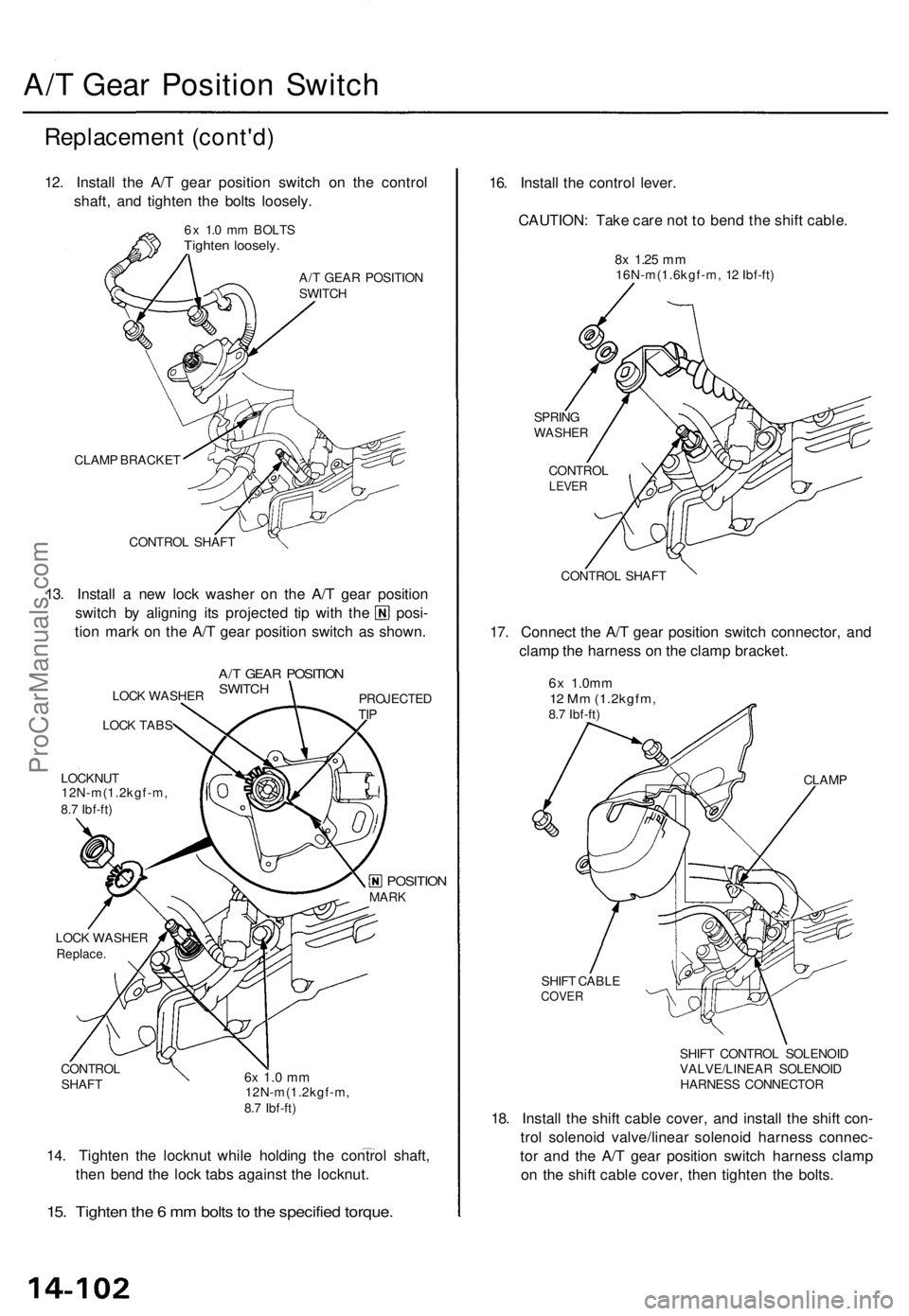
A/T Gea r Positio n Switc h
Replacemen t (cont'd )
12. Instal l th e A/ T gea r positio n switc h o n th e contro l
shaft , an d tighte n th e bolt s loosely .
6x 1. 0 m m BOLT STighten loosely .
A/T GEA R POSITIO N
SWITC H
CLAM P BRACKE T
CONTRO L SHAF T
13. Instal l a ne w loc k washe r o n th e A/ T gea r positio n
switch b y alignin g it s projecte d ti p wit h th e posi -
tio n mar k o n th e A/ T gea r positio n switc h a s shown .
LOCK WASHE R
LOC K TAB S
LOCKNU T
12N-m(1.2kgf-m ,
8. 7 Ibf-ft )
A/T GEA R POSITIO NSWITCHPROJECTE DTIP
LOC K WASHE RReplace.
CONTRO L
SHAF T6x 1. 0 m m12N-m(1.2kgf-m ,
8. 7 Ibf-ft )
14. Tighte n th e locknu t whil e holdin g th e contro l shaft ,
the n ben d th e loc k tab s agains t th e locknut .
15. Tighte n th e 6 m m bolt s to th e specifie d torque .
16. Instal l th e contro l lever .
CAUTION : Tak e car e no t t o ben d th e shif t cable .
8x 1.2 5 mm16N-m(1.6kgf-m , 1 2 Ibf-ft )
SPRIN G
WASHE R
CONTRO LLEVER
CONTRO L SHAF T
17. Connec t th e A/ T gea r positio n switc h connector , an d
clam p th e harnes s o n th e clam p bracket .
6x 1.0m m12 M m (1.2kgfm ,8.7 Ibf-ft )
CLAMP
SHIF T CABL E
COVER
SHIFT CONTRO L SOLENOI D
VALVE/LINEA R SOLENOI D
HARNES S CONNECTO R
18. Instal l th e shif t cabl e cover , an d instal l th e shif t con -
tro l solenoi d valve/linea r solenoi d harnes s connec -
to r an d th e A/ T gea r positio n switc h harnes s clam p
o n th e shif t cabl e cover , the n tighte n th e bolts .
MARKPOSITIO N
ProCarManuals.com
Page 319 of 1771
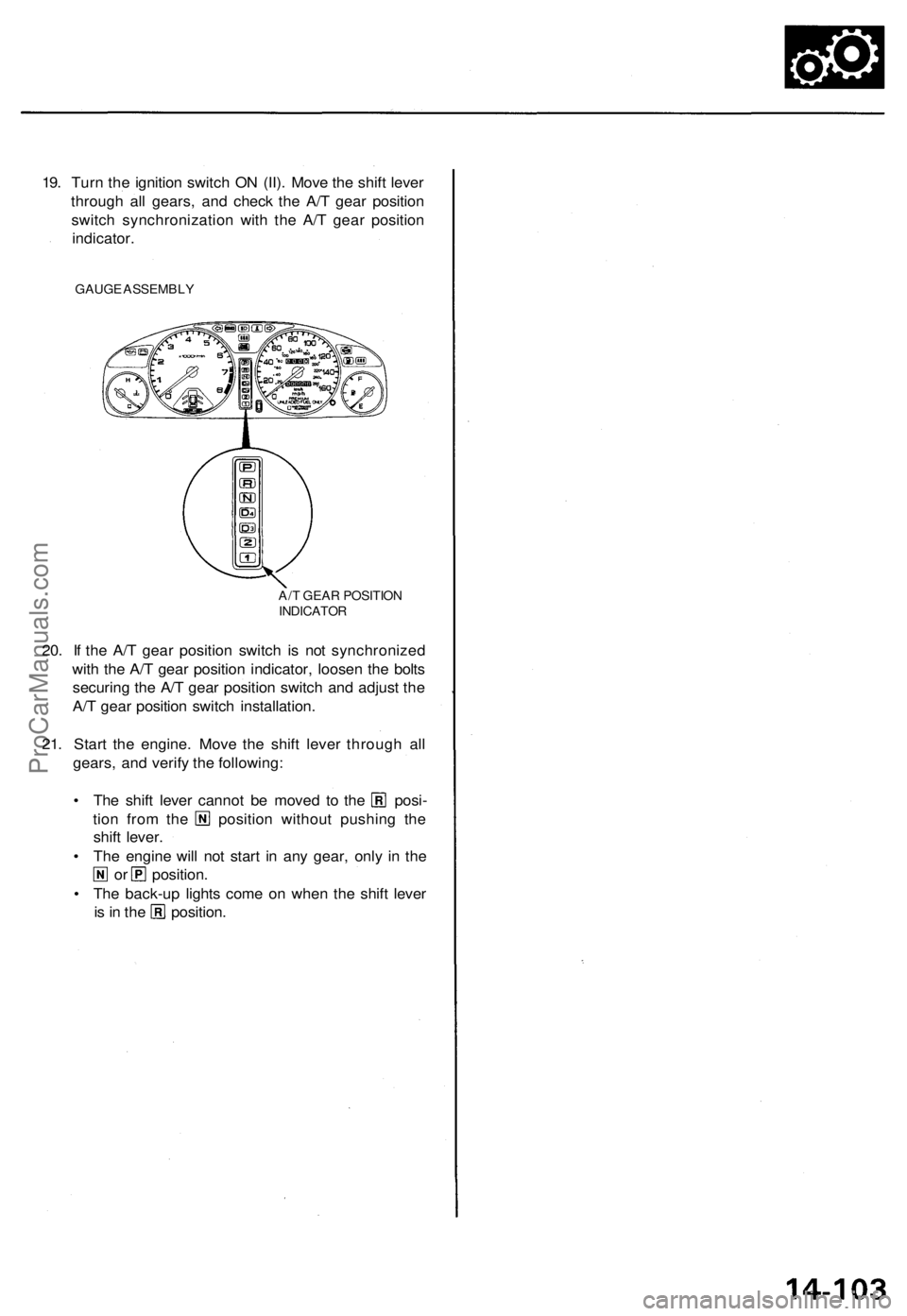
19. Turn the ignition switch ON (II). Move the shift lever
through all gears, and check the A/T gear position
switch synchronization with the A/T gear position
indicator.
GAUGE ASSEMBLY
20. If the A/T gear position switch is not synchronized
with the A/T gear position indicator, loosen the bolts
securing the A/T gear position switch and adjust the
A/T gear position switch installation.
21. Start the engine. Move the shift lever through all
gears, and verify the following:
• The shift lever cannot be moved to the posi-
tion from the position without pushing the
shift lever.
• The engine will not start in any gear, only in the
or position.
• The back-up lights come on when the shift lever
is in the position.
A/T GEAR POSITION
INDICATORProCarManuals.com
Page 320 of 1771
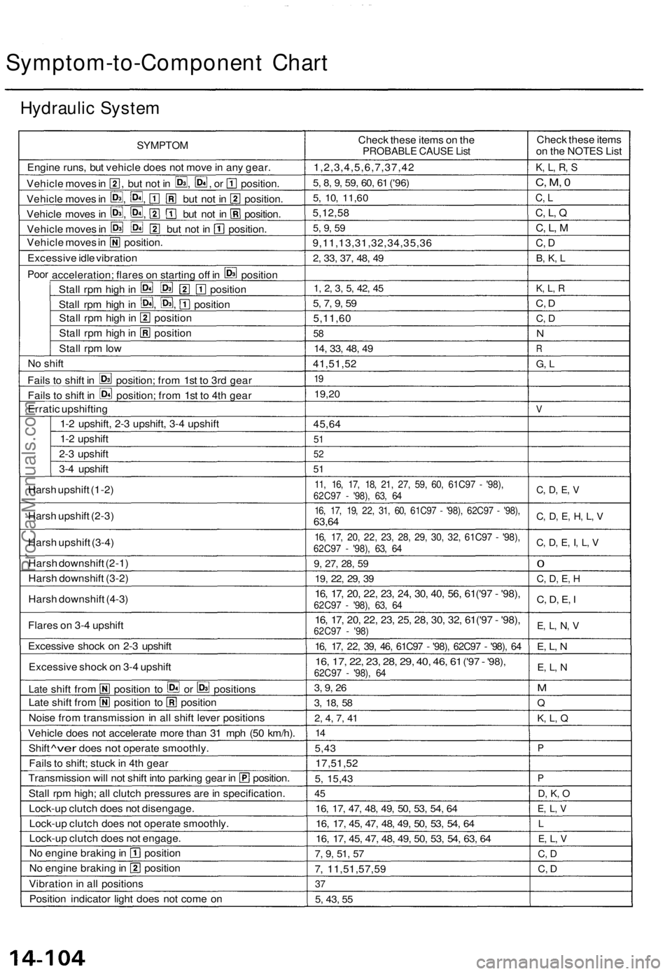
Symptom-to-Component Chart
Hydraulic System
SYMPTOM
Engine runs, but vehicle does not move in any gear.
Vehicle moves in , but not in , , or position.
Vehicle moves in , , but not in position.
Vehicle moves in , , but not in position.
Vehicle moves in but not in position.
Vehicle moves in position.
Excessive idle vibration
Poor
acceleration; flares on starting off in position
Stall rpm high in position
Stall rpm high in , , position
Stall rpm high in position
Stall rpm high in position
Stall rpm low
No shift
Fails to shift in position; from 1st to 3rd gear
Fails to shift in position; from 1st to 4th gear
Erratic upshifting
1-2 upshift, 2-3 upshift, 3-4 upshift
1-2 upshift
2-3 upshift
3-4 upshift
Harsh upshift (1-2)
Harsh upshift (2-3)
Harsh upshift (3-4)
Harsh downshift (2-1)
Harsh downshift (3-2)
Harsh downshift (4-3)
Flares on 3-4 upshift
Excessive shock on 2-3 upshift
Excessive shock on 3-4 upshift
Late
shift from position to or positions
Late shift from position to position
Noise from transmission in all shift lever positions
Vehicle does not accelerate more than 31 mph (50 km/h).
Shift
^ver
does
not
operate smoothly.
Fails to shift; stuck in 4th gear
Transmission will not shift into parking gear in position.
Stall
rpm high; all clutch pressures are in specification.
Lock-up clutch does not disengage.
Lock-up clutch does not operate smoothly.
Lock-up clutch does not engage.
No engine braking in position
No engine braking in position
Vibration in all positions
Position indicator light does not come on
Check these items on the
PROBABLE CAUSE List
1,2,3,4,5,6,7,37,42
5, 8, 9, 59, 60, 61
('96)
5, 10,
11,60
5,12,58
5, 9, 59
9,11,13,31,32,34,35,36
2, 33, 37, 48, 49
1, 2, 3, 5, 42, 45
5, 7, 9, 59
5,11,60
58
14, 33, 48, 49
41,51,52
19
19,20
45,64
51
52
51
11, 16, 17, 18, 21, 27, 59, 60, 61C97 - '98),
62C97 - '98), 63, 64
16, 17, 19, 22, 31, 60, 61C97 - '98), 62C97 - '98),
63,64
16, 17, 20, 22, 23, 28, 29, 30, 32, 61C97 - '98),
62C97 - '98), 63, 64
9, 27, 28, 59
19, 22, 29, 39
16, 17, 20, 22, 23, 24, 30, 40, 56, 61('97 - '98),
62C97 - '98), 63, 64
16, 17, 20, 22, 23, 25, 28, 30, 32, 61('97 - '98),
62C97 - '98)
16, 17, 22, 39, 46, 61C97 - '98), 62C97 - '98), 64
16, 17, 22, 23, 28, 29, 40, 46, 61
('97
-
'98),
62C97 - '98), 64
3, 9, 26
3, 18, 58
2, 4, 7, 41
14
5,43
17,51,52
5,
15,43
45
16, 17, 47, 48, 49, 50, 53, 54, 64
16, 17, 45, 47, 48, 49, 50, 53, 54, 64
16, 17, 45, 47, 48, 49, 50, 53, 54, 63, 64
7, 9, 51, 57
7, 11,51,57,59
37
5, 43, 55
Check these items
on the NOTES List
K, L, R, S
C, M, 0
C, L
C, L, Q
C, L, M
C, D
B, K, L
K, L, R
C, D
C, D
N
R
G, L
V
C, D, E, V
C, D, E, H, L, V
C, D, E, I, L, V
0
C, D, E, H
C, D, E, I
E, L, N, V
E, L, N
E, L, N
M
Q
K, L, Q
P
P
D, K, O
E, L, V
L
E, L, V
C, D
C, DProCarManuals.com