ACURA TL 1995 Service Repair Manual
Manufacturer: ACURA, Model Year: 1995, Model line: TL, Model: ACURA TL 1995Pages: 1771, PDF Size: 62.49 MB
Page 811 of 1771
Oil Pum p
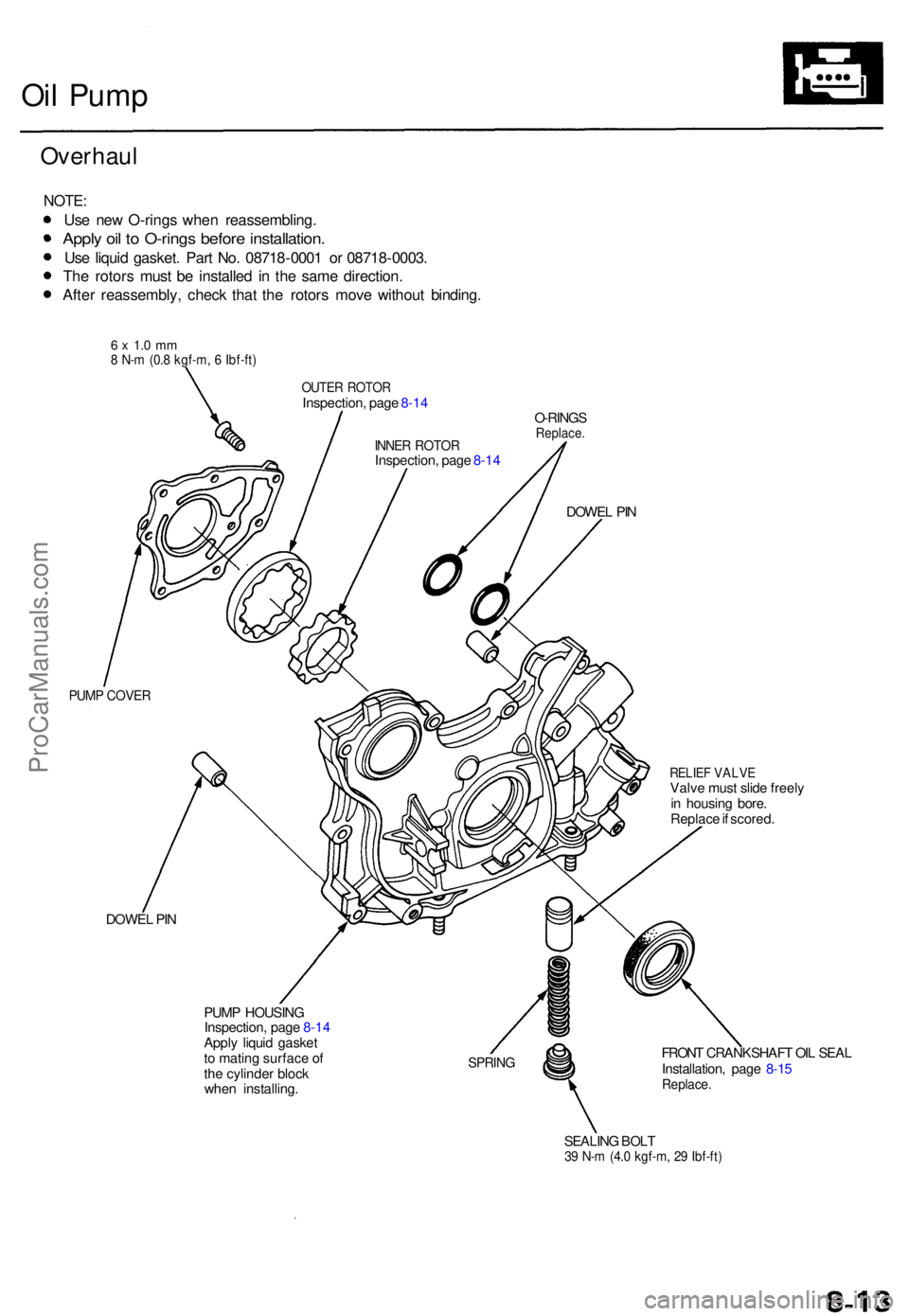
Overhau l
NOTE:
Use ne w O-ring s whe n reassembling .
Apply oi l t o O-ring s befor e installation .
Use liqui d gasket . Par t No . 0871 8-000 1 o r 0871 8-0003 .
Th e rotor s mus t b e installe d i n th e sam e direction .
Afte r reassembly , chec k tha t th e rotor s mov e withou t binding .
6 x 1. 0 m m8 N- m (0. 8 kgf-m , 6 Ibf-ft )
OUTE R ROTO RInspection , pag e 8-1 4
O-RINGS
Replace .
DOWEL PI N
PUM P COVE R
RELIEF VALV EValve mus t slid e freel y
i n housin g bore .
Replac e if scored .
DOWE L PI N
PUMP HOUSIN G
Inspection , pag e 8-1 4
Appl y liqui d gaske t
t o matin g surfac e o f
th e cylinde r bloc k
whe n installing .
SPRING FRON T CRANKSHAF T OI L SEA L
Installation , pag e 8-1 5
Replace .
SEALING BOL T39 N- m (4. 0 kgf-m , 2 9 Ibf-ft )
INNER ROTO RInspection , pag e 8-1 4
ProCarManuals.com
Page 812 of 1771
Oil Pum p
Removal/lnspection/lnstallatio n
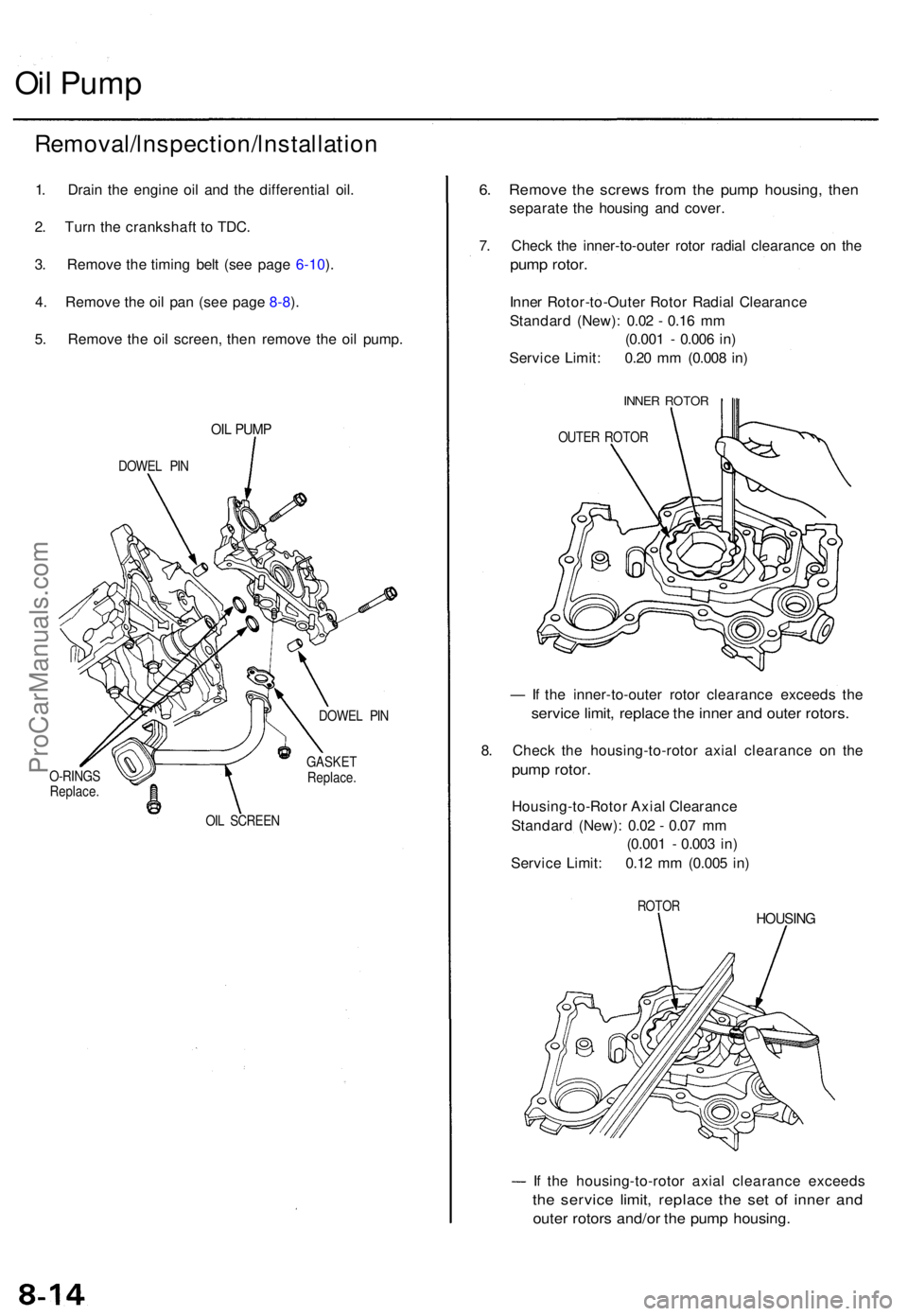
1. Drai n th e engin e oi l an d th e differentia l oil .
2 . Tur n th e crankshaf t t o TDC .
3 . Remov e th e timin g bel t (se e pag e 6-10 ).
4 . Remov e th e oi l pa n (se e pag e 8-8 ).
5 . Remov e th e oi l screen , the n remov e th e oi l pump .
OIL PUM P
DOWE L PI N
O-RING S
Replace . DOWE
L PI N
GASKE T
Replace .
OI L SCREE N
6. Remov e th e screw s fro m th e pum p housing , the n
separat e th e housin g an d cover .
7 . Chec k th e inner-to-oute r roto r radia l clearanc e o n th e
pum p rotor .
Inner Rotor-to-Oute r Roto r Radia l Clearanc e
Standar d (New) : 0.0 2 - 0.1 6 m m
(0.00 1 - 0.00 6 in )
Servic e Limit : 0.2 0 m m (0.00 8 in )
INNE R ROTO R
OUTER ROTO R
— If th e inner-to-oute r roto r clearanc e exceed s th e
servic e limit , replac e th e inne r an d oute r rotors .
8. Chec k th e housing-to-roto r axia l clearanc e o n th e
pum p rotor .
Housing-to-Roto r Axia l Clearanc e
Standar d (New) : 0.0 2 - 0.0 7 m m
(0.00 1 - 0.00 3 in )
Servic e Limit : 0.1 2 m m (0.00 5 in )
ROTO RHOUSIN G
If th e housing-to-roto r axia l clearanc e exceed s
the servic e limit , replac e th e se t of inne r an d
oute r rotor s and/o r th e pum p housing .
ProCarManuals.com
Page 813 of 1771
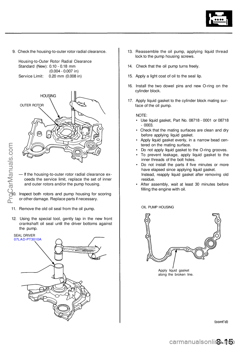
9. Chec k th e housing-to-oute r roto r radia l clearance .
Housing-to-Oute r Roto r Radia l Clearanc e
Standard (New) : 0.1 0 - 0.1 8 m m
(0.00 4 - 0.00 7 in )
Servic e Limit : 0.2 0 m m (0.00 8 in )
HOUSIN G
OUTER ROTO R
— If th e housing-to-oute r roto r radia l clearanc e ex -
ceed s th e servic e limit , replac e th e se t o f inne r
an d oute r rotor s and/o r th e pum p housing .
10. Inspec t bot h rotor s an d pum p housin g fo r scorin g
or othe r damage . Replac e part s if necessary .
11 . Remov e th e ol d oi l sea l fro m th e oi l pump .
12 . Usin g th e specia l tool , gentl y ta p i n th e ne w fron t
crankshaf t oi l sea l unti l th e drive r bottom s agains t
th e pump .
SEAL DRIVE R07LAD-PT3010 A
13. Reassembl e th e oi l pump , applyin g liqui d threa d
loc k t o th e pum p housin g screws .
14 . Chec k tha t th e oi l pum p turn s freely .
15 . Appl y a ligh t coa t o f oi l t o th e sea l lip .
16 . Instal l th e tw o dowe l pin s an d ne w O-rin g o n th e
cylinde r block .
17 . Appl y liqui d gaske t t o th e cylinde r bloc k matin g sur -
fac e o f th e oi l pump .
NOTE:
• Us e liqui d gasket , Par t No . 0871 8 - 000 1 o r 0871 8
- 0003 .
• Chec k tha t th e matin g surfaces are clea n an d dr y
befor e applyin g liqui d gasket .
• Appl y liqui d gaske t evenly , i n a narro w bea d cen -
tere d o n th e matin g surface .
• D o no t appl y liqui d gaske t t o th e O-rin g grooves .
• T o preven t leakage , appl y liqui d gaske t t o th e
inne r thread s o f th e bol t holes .
• D o no t instal l th e part s i f fiv e minute s o r mor e
hav e elapse d sinc e applyin g liqui d gasket .
Instead , reappl y liqui d gaske t afte r removin g ol d
residue .
• Afte r assembly , wai t a t leas t 3 0 minute s befor e
filling th e engin e wit h oil .
OIL PUM P HOUSIN G
Apply liqui d gaske t
alon g th e broke n line .
ProCarManuals.com
Page 814 of 1771
Removal/lnspection/lnstallation
(cont'd)
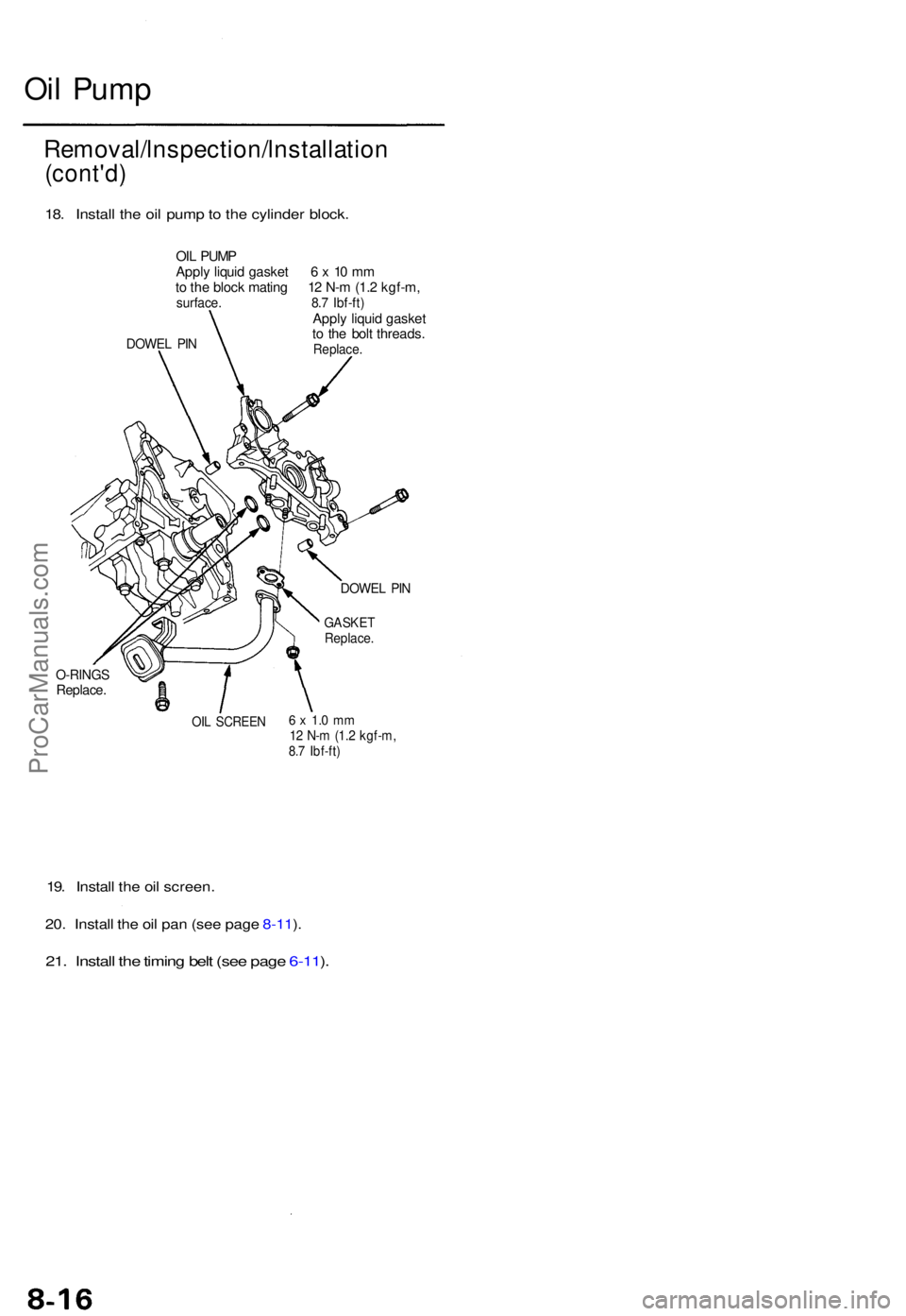
18. Instal l th e oi l pum p to th e cylinde r block .
OIL PUM P
Appl y liqui d gaske t 6 x 10 m m
t o th e bloc k matin g 1 2 N- m (1. 2 kgf-m ,
surface . 8. 7 Ibf-ft )Apply liqui d gaske t
t o th e bol t threads .
Replace .DOWEL PI N
O-RING SReplace .
OIL SCREE N6 x 1. 0 m m12 N- m (1. 2 kgf-m ,8.7 Ibf-ft )
19. Instal l th e oi l screen .
20 . Instal l th e oi l pa n (se e pag e 8-11 ).
21 . Instal l th e timin g bel t (se e pag e 6-11 ).
DOWE L PI N
GASKE TReplace .
Oil Pum p
ProCarManuals.com
Page 815 of 1771
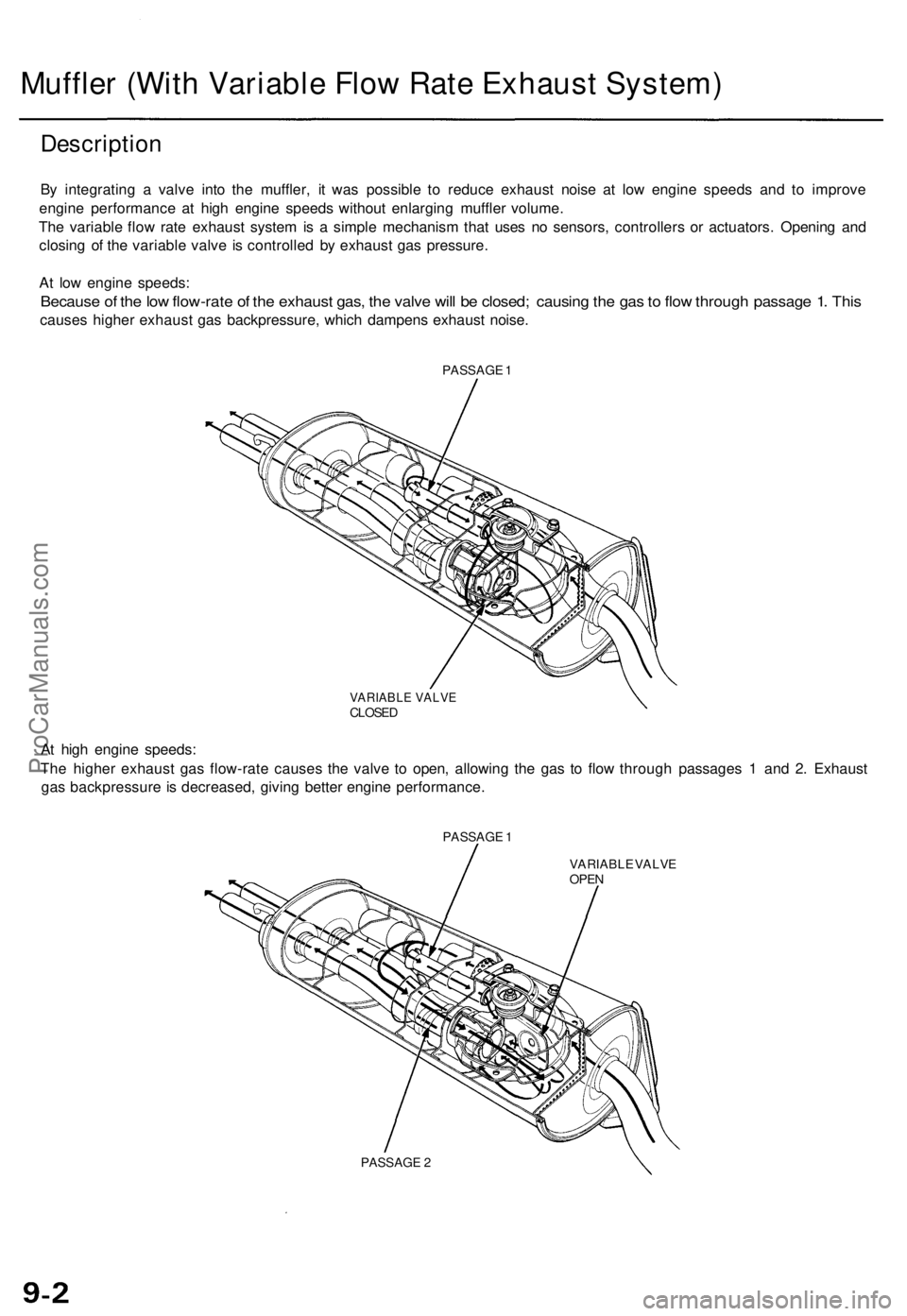
Description
By integratin g a valv e int o th e muffler , i t wa s possibl e t o reduc e exhaus t nois e a t lo w engin e speed s an d t o improv e
engin e performanc e a t hig h engine speeds withou t enlargin g muffle r volume .
Th e variabl e flo w rat e exhaus t syste m is a simpl e mechanis m tha t use s n o sensors , controller s o r actuators . Openin g an d
closin g o f th e variabl e valv e i s controlle d b y exhaus t ga s pressure .
A t lo w engin e speeds :
Because o f th e lo w flow-rat e o f th e exhaus t gas , th e valv e wil l b e closed ; causin g th e ga s to flo w throug h passag e 1 . Thi s
cause s highe r exhaus t ga s backpressure , whic h dampen s exhaus t noise .
PASSAG E 1
VARIABL E VALV ECLOSE D
At hig h engine speeds :
Th e highe r exhaus t ga s flow-rat e cause s th e valv e t o open , allowin g th e ga s t o flo w throug h passage s 1 an d 2 . Exhaust
ga s backpressur e is decreased , givin g bette r engin e performance .
PASSAGE 1
VARIABLE VALV E
OPE N
PASSAG E 2
Muffle r (Wit h Variabl e Flo w Rat e Exhaus t System )
ProCarManuals.com
Page 816 of 1771
Intake Manifol d
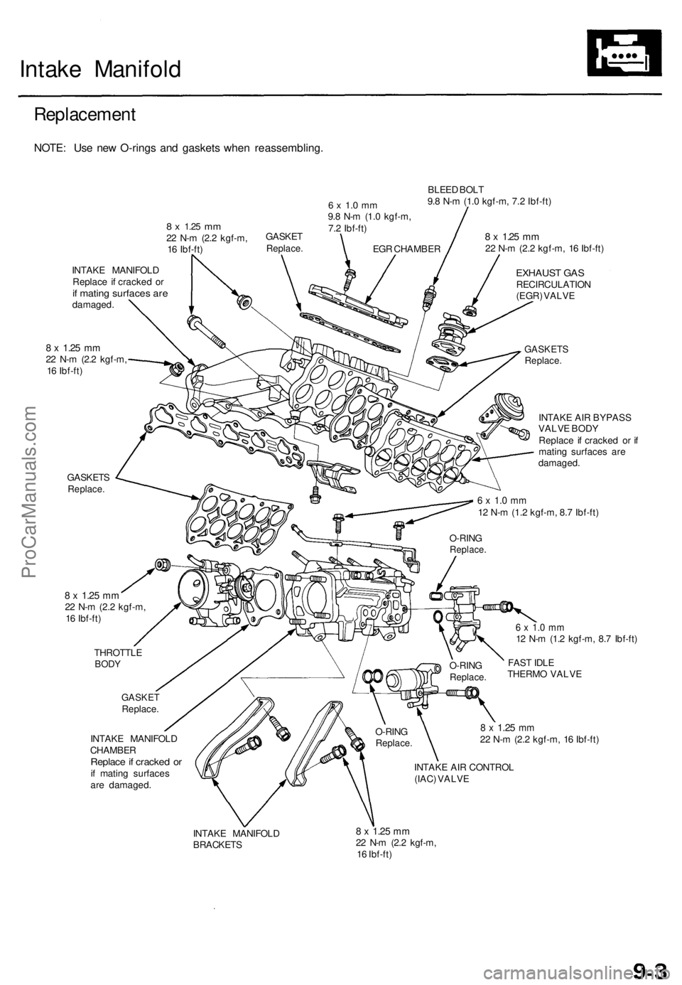
Replacemen t
NOTE: Us e ne w O-ring s an d gasket s whe n reassembling .
8 x 1.2 5 mm22 N- m (2. 2 kgf-m ,
1 6 Ibf-ft )
6 x 1. 0 m m9.8 N- m (1. 0 kgf-m ,
7. 2 Ibf-ft ) BLEE
D BOL T
9. 8 N- m (1. 0 kgf-m , 7. 2 Ibf-ft )
INTAK E MANIFOL D
Replac e i f cracke d o r
if matin g surface s ar edamaged .
8 x 1.2 5 mm22 N- m (2. 2 kgf-m ,
1 6 Ibf-ft )
GASKET S
Replace.
8 x 1.2 5 m m22 N- m (2. 2 kgf-m , 1 6 Ibf-ft )
EXHAUS T GA SRECIRCULATIO N
(EGR ) VALV E
GASKET SReplace.
INTAKE AI R BYPAS S
VALV E BOD Y
Replac e i f cracke d o r i f
matin g surface s ar e
damaged .
6 x 1. 0 m m12 N- m (1. 2 kgf-m , 8. 7 Ibf-ft )
8 x 1.2 5 mm22 N- m (2. 2 kgf-m ,
1 6 Ibf-ft )
THROTTL E
BODY
GASKE TReplace .
INTAK E MANIFOL D
CHAMBE R
Replace if cracke d o rif matin g surface s
ar e damaged .
6 x 1. 0 m m12 N- m (1. 2 kgf-m , 8. 7 Ibf-ft )
FAS T IDL E
THERM O VALV E
8 x 1.2 5 mm22 N- m (2. 2 kgf-m , 1 6 Ibf-ft )
INTAK E AI R CONTRO L
(IAC ) VALV E
INTAK E MANIFOL D
BRACKET S
8 x 1.2 5 mm22 N- m (2. 2 kgf-m ,
1 6 Ibf-ft )
O-RIN
G
Replace .
O-RINGReplace .
O-RINGReplace .
EGR CHAMBE R
GASKE
TReplace .
ProCarManuals.com
Page 817 of 1771
Exhaust Manifol d
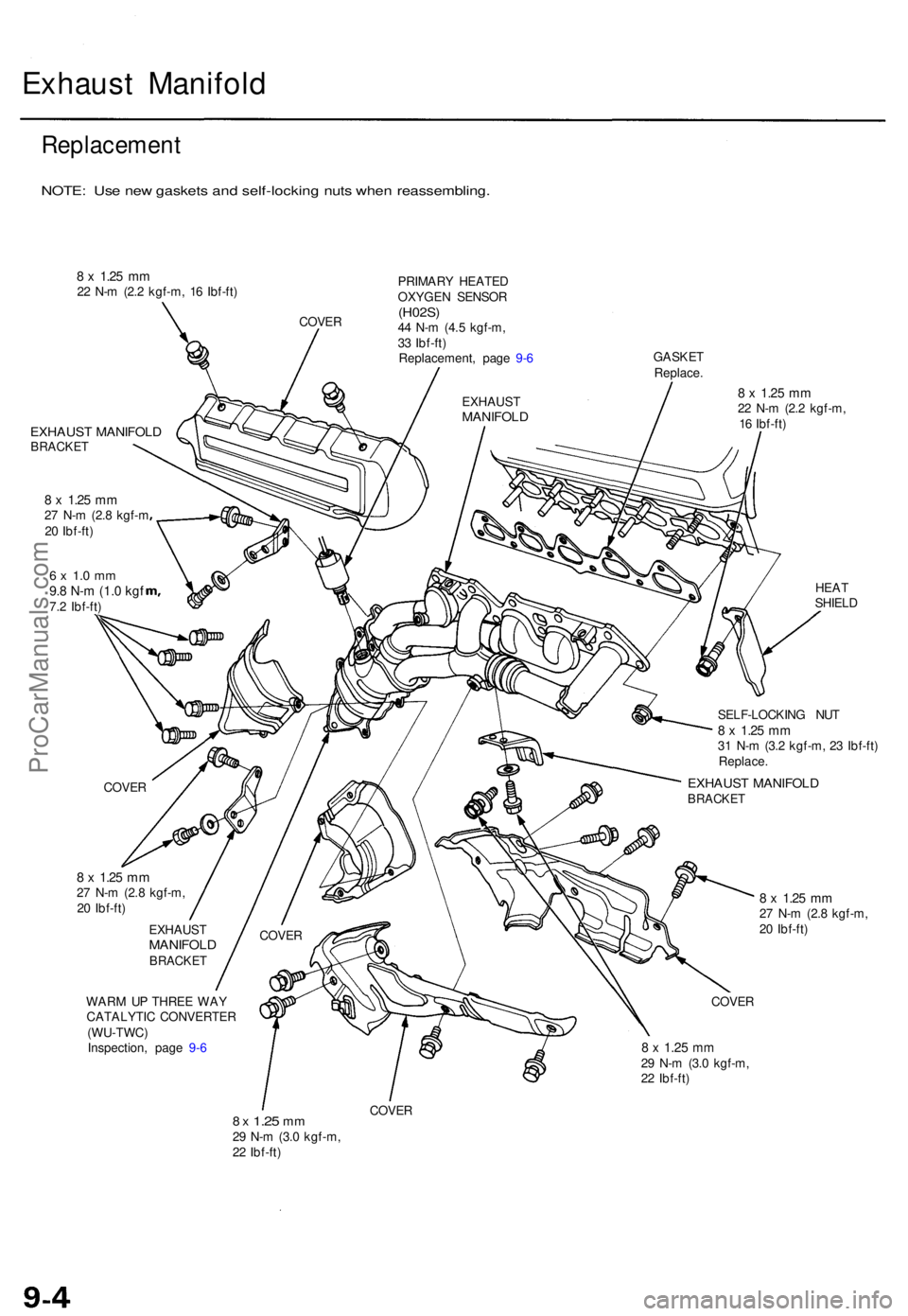
Replacemen t
NOTE: Us e ne w gasket s an d self-lockin g nut s whe n reassembling .
8 x 1.2 5 mm22 N- m (2. 2 kgf-m , 1 6 Ibf-ft )
COVER PRIMAR
Y HEATE D
OXYGE N SENSO R
(H02S)44 N- m (4. 5 kgf-m ,
3 3 Ibf-ft )
Replacement , pag e 9- 6 GASKE
T
Replace .
EXHAUS T MANIFOL DBRACKET
8 x 1.2 5 mm27 N- m (2. 8 kgf- m
2 0 Ibf-ft )
6 x 1. 0 m m9.8 N- m (1. 0 kg f7.2 Ibf-ft )
8 x 1.2 5 mm22 N- m (2. 2 kgf-m ,
1 6 Ibf-ft )
HEAT
SHIEL D
SELF-LOCKIN G NU T
8 x 1.2 5 m m31 N- m (3. 2 kgf-m , 2 3 Ibf-ft )Replace .
8 x 1.2 5 mm27 N- m (2. 8 kgf-m ,
2 0 Ibf-ft )
EXHAUS T
MANIFOL DBRACKET
WARM U P THRE E WA Y
CATALYTI C CONVERTE R
(WU-TWC )
Inspection , pag e 9- 6
8 x 1.2 5 mm27 N- m (2. 8 kgf-m ,
2 0 Ibf-ft )
COVE R
8 x 1.2 5 mm29 N- m (3. 0 kgf-m ,
2 2 Ibf-ft )
8 x 1.2 5 mm29 N- m (3. 0 kgf-m ,
2 2 Ibf-ft )
COVE R
EXHAUS TMANIFOL D
EXHAUST MANIFOL DBRACKETCOVER
COVER
ProCarManuals.com
Page 818 of 1771
Exhaust Pip e an d Muffle r
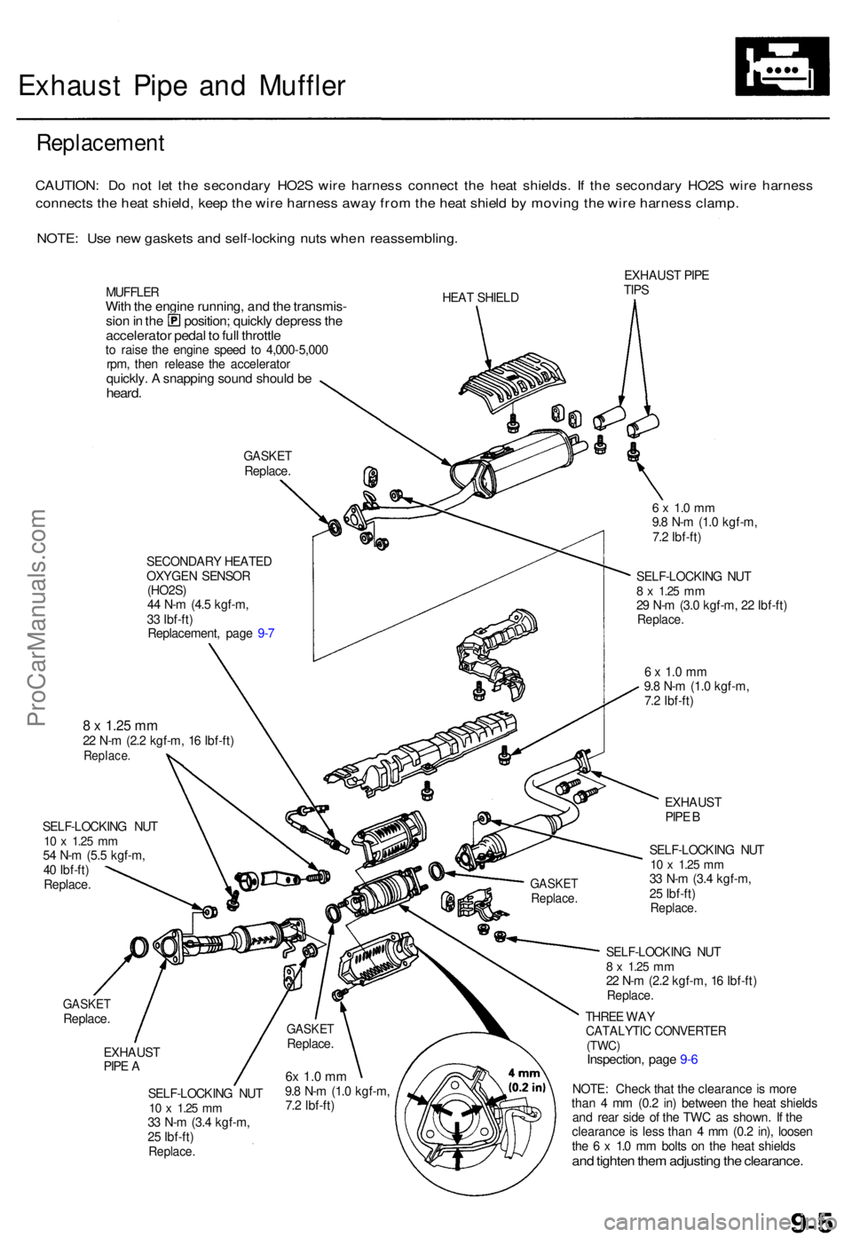
Replacemen t
CAUTION: D o no t le t th e secondar y HO2 S wir e harnes s connec t th e hea t shields . I f th e secondar y HO2 S wir e harnes s
connect s th e hea t shield , kee p th e wir e harnes s awa y fro m th e hea t shiel d b y movin g th e wir e harnes s clamp .
NOTE: Us e ne w gasket s an d self-lockin g nut s whe n reassembling .
MUFFLERWith th e engin e running , an d th e transmis -sion in th e position ; quickl y depres s th eaccelerato r peda l t o ful l throttl eto rais e th e engin e spee d t o 4,00 0-5,00 0
rpm , the n releas e th e accelerato r
quickly. A snappin g soun d shoul d b eheard .
GASKE TReplace .
SECONDAR Y HEATE D
OXYGE N SENSO R
(HO2S )
4 4 N- m (4. 5 kgf-m ,
3 3 Ibf-ft )
Replacement , pag e 9- 7 HEA
T SHIEL D EXHAUS
T PIP E
TIP S
GASKE TReplace .
8 x 1.2 5 mm22 N- m (2. 2 kgf-m , 1 6 Ibf-ft )Replace .
SELF-LOCKIN G NU T10 x 1.2 5 mm54 N- m (5. 5 kgf-m ,
4 0 Ibf-ft )
Replace .
6 x 1. 0 m m9.8 N- m (1. 0 kgf-m ,
7. 2 Ibf-ft )
SELF-LOCKIN G NU T
8 x 1.2 5 mm29 N- m (3. 0 kgf-m , 2 2 Ibf-ft )Replace .
6 x 1. 0 m m9.8 N- m (1. 0 kgf-m ,
7. 2 Ibf-ft )
EXHAUS T
PIP E A
SELF-LOCKIN G NU T
10 x 1.2 5 mm33 N- m (3. 4 kgf-m ,
2 5 Ibf-ft )
Replace .
EXHAUS T
PIP E B
SELF-LOCKIN G NU T
10 x 1.2 5 mm33 N- m (3. 4 kgf-m ,
2 5 Ibf-ft )
Replace .
SELF-LOCKIN G NU T8 x 1.2 5 mm22 N- m (2. 2 kgf-m , 1 6 Ibf-ft )Replace .
THREE WA YCATALYTI C CONVERTE R(TWC)Inspection , pag e 9- 6
NOTE : Chec k tha t th e clearanc e is mor e
tha n 4 m m (0. 2 in ) betwee n th e hea t shield s
an d rea r sid e o f th e TW C a s shown . I f th e
clearanc e is les s tha n 4 m m (0. 2 in) , loose n
th e 6 x 1. 0 m m bolt s o n th e hea t shield s
and tighte n the m adjustin g th e clearance .
6x 1. 0 m m9.8 N- m (1. 0 kgf-m ,
7. 2 Ibf-ft )
GASKE TReplace .
GASKETReplace .
ProCarManuals.com
Page 819 of 1771
TWC/WU-TWC
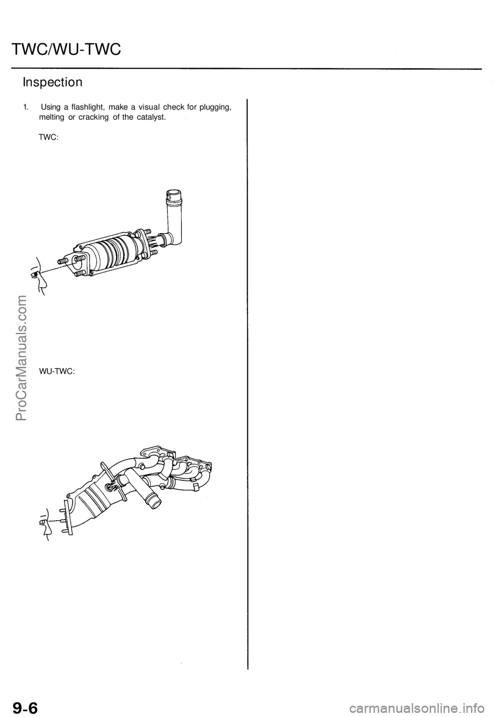
Inspection
1. Usin g a flashlight , mak e a visua l chec k fo r plugging ,
meltin g o r crackin g o f th e catalyst .
TWC:
WU-TWC :
ProCarManuals.com
Page 820 of 1771
HO2S
Replacemen t
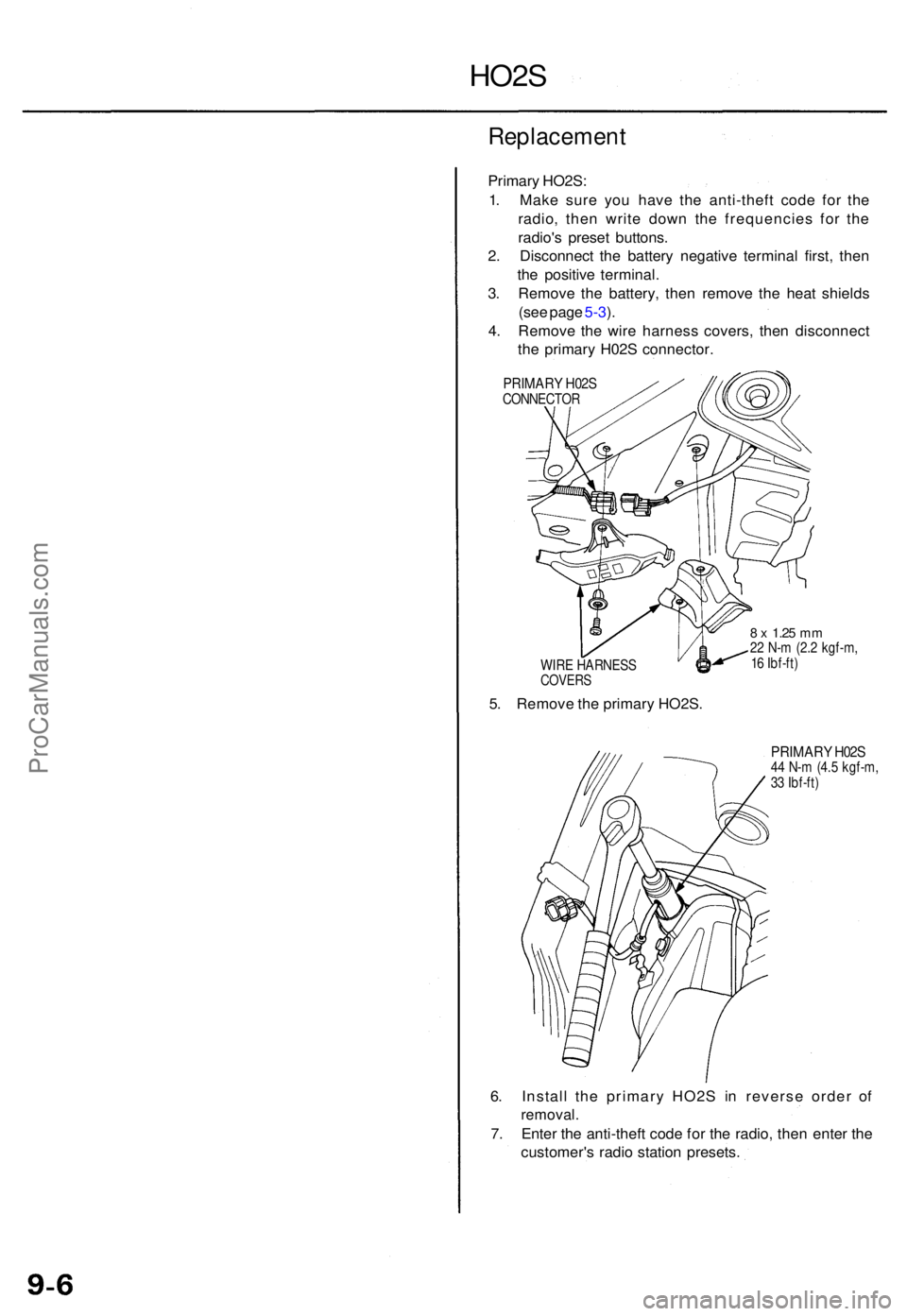
Primary HO2S :
1 . Mak e sur e yo u hav e th e anti-thef t cod e fo r th e
radio , the n writ e dow n th e frequencie s fo r th e
radio' s prese t buttons .
2 . Disconnec t th e batter y negativ e termina l first , the n
th e positiv e terminal .
3 . Remov e th e battery , the n remov e th e hea t shield s
(se e pag e 5-3 ).
4 . Remov e th e wir e harnes s covers , the n disconnec t
th e primar y H02 S connector .
PRIMARY H02 SCONNECTO R
WIR E HARNES S
COVERS
5. Remov e th e primar y HO2S .
8 x 1.2 5 mm22 N- m (2. 2 kgf-m ,
1 6 Ibf-ft )
PRIMAR Y H02 S44 N- m (4. 5 kgf-m ,
3 3 Ibf-ft )
6. Instal l th e primar y HO2 S i n revers e orde r o f
removal .
7. Ente r th e anti-thef t cod e fo r th e radio , the n ente r th e
customer' s radi o statio n presets .
ProCarManuals.com