ALFA ROMEO GIULIA 2023 Repair Manual
Manufacturer: ALFA ROMEO, Model Year: 2023, Model line: GIULIA, Model: ALFA ROMEO GIULIA 2023Pages: 248, PDF Size: 9.62 MB
Page 61 of 248
59
The sunroof has three preset positions:
Fully closed
Comfort (intermediate opening)
Fully open
NOTE:
You cannot have the sunshade closed when the
sunroof is open.
OPENING AND CLOSING THE SUNROOF
To open the sunroofs front panel, push the open/
close button toward the rear of the vehicle to
open to the comfort position (half-way). Pushing
the button a second time will open to the fully
open position.
To close the sunroof, push the open/close button
toward the front of the vehicle. The roof will close
completely.
The automatic motion can be interrupted in any
position by pushing the open/close button again.
VENTING SUNROOF
To bring the roof into vent position, push and
release the vent button.
This type of vent opening can be activated
regardless of the position of the sunroof. When
starting with the roof in the closed position,
pushing the vent button automatically causes the
sunroof to open to the vent position. If the roof is
already open, the button must be held until the
roof reaches the vent-opening position.
Pushing vent button again during automatic
movement of the roof will stop it.
SUNSHADE OPERATION
The front sunshade is power operated.
Push the Power Shade open/close button toward
the rear of the vehicle to open the front sun shade
to the three quarter open position. Pushing the
button a second time will open the sunshade
completely.
Push the Power Shade open/close button toward
the front of the vehicle to close the sun shade.
The automatic motion can be interrupted in any
position by pushing the Power Shade open/close
button again.
To open the rear sunshade, pull sunshade
manually toward the rear of the vehicle.
PINCH PROTECT FEATURE
The sunroof has an anti-pinch safety system
capable of detecting the presence of an obstacle
during the closing movement. If an obstacle is
detected, the system intervenes and the
movement of the sunroof is immediately reversed
into opening.
RE-INITIALIZATION PROCEDURE
Automatic operation of the sunroof must be
re-initialized in case of faulty sunroof operation. It
may also be necessary to re-initialize the sunroof
after the vehicle’s battery has been disconnected
and then reconnected.
NOTE:
The anti-pinch safety device is deactivated during
the re-initialization procedure.
WARNING!
Never leave children unattended in a vehicle,
or with access to an unlocked vehicle. Never
leave the key fob in or near the vehicle, or in
a location accessible to children. Do not
leave the ignition of a vehicle equipped with
keyless ignition in the ON/RUN position.
Occupants, particularly unattended children,
can become entrapped by the power sunroof
while operating the power sunroof switch.
Such entrapment may result in serious injury
or death.
In a collision, there is a greater risk of being
thrown from a vehicle with an open sunroof.
You could also be seriously injured or killed.
Always fasten your seat belt properly and
make sure all passengers are also properly
secured.
Do not allow small children to operate the
sunroof. Never allow your fingers, other body
parts, or any object, to project through the
sunroof opening. Injury may result.
CAUTION!
Do not open the sunroof if a luggage roof rack
or crossbars are fitted. Do not open the
sunroof if there is snow or ice on it: you may
damage it.
23_GA_OM_EN_USC_t.book Page 59
Page 62 of 248
GETTING TO KNOW YOUR VEHICLE
60
Proceed as follows:
1. With the ignition in the ON/RUN position, make sure the sunroof glass is fully closed
(sunshade open).
2. Open the driver’s side door, and place the ignition in the OFF position.
3. Within five seconds, place the ignition in the ACC or ON/RUN position.
4. Within 10 seconds, push and hold the sunroof close switch (forward). After 8 - 10
seconds of holding the switch, the re-initial -
ization process will begin. Continue to hold
the switch while the sunroof motor cycles,
and the sunshade will fully close.
5. Once the sunroof glass and the power sunshade have stopped motion, release the
sunroof close switch, then push and hold it
again within five seconds. Continue to hold
the switch while the sunshade fully opens,
the sunroof glass fully opens, followed by the
glass fully closing then the sunshade fully
closing.
6. Release the switch once the operations stop. Re-initialization of the sunroof motor is now
complete.
NOTE:
If the switch is released prior to full completion of
the operations described, the entire re-initializa -
tion procedure must be repeated from step 1.
7. Confirm express operations for the sunroof glass and sunshade are functional for
opening and closing operations.
SUNROOF MAINTENANCE
Use only a non-abrasive cleaner and a soft cloth
to clean the glass panel. Periodically check for
and clear out any debris that may have collected
in the tracks.
HOOD
OPENING THE HOOD
To open the hood, two latches must be released.
1. Pull the release lever located underneath the driver’s side of the instrument panel.
Hood Release Lever
2. Lift the hood slightly. Move the underhood latch from right to left to release the hood. Release Hood Latch To The Left
3. Raise the hood completely. The operation is assisted by the addition of two gas props
which hold it in the open position.
NOTE:
Use both hands to lift the hood. Before lifting,
check that the windshield wiper arms are not
raised from the windshield or in operation.
WARNING!
Before opening the hood, apply the Electric
Park Brake (EPB) and place the gear selector
in PARK (P). Otherwise the vehicle may roll and
cause damage, serious injury, or death.
CAUTION!
Do not tamper with the gas props.
23_GA_OM_EN_USC_t.book Page 60
Page 63 of 248
61
CLOSING THE HOOD
To close, lower the hood to approximately
16 inches (40 cm) from the engine compartment
then let it drop. Make sure that the hood is
completely closed and fully latched.
NOTE:
Since the hood is equipped with a double locking
system, one for each side, check that it is closed
on both its sides.
TRUNK
The trunk unlocking is electrically operated and is
deactivated when the vehicle is in motion.
OPENING
Opening From The Outside
When unlocked, the trunk lid can be opened from
outside the vehicle using the exterior trunk lid
release button located between the plate lights.
Push the button until you hear a “click.” The trunk
lid can also be opened by quickly pushing the
trunk lid release button on the key fob twice.Exterior Trunk Lid Release Button
The turn signal indicators will blink and the
interior lights will turn on when the trunk lid is
opened. They turn off automatically when the
trunk lid is closed.
The interior lights turn off automatically after a
few minutes if the trunk lid is left open.
Opening From The Inside
When unlocked, the trunk lid can be opened from
inside the vehicle using the interior trunk lid
release button, located under the dashboard
near the engine hood opening lever. Push the
trunk lid release button until you hear a “click.” Interior Trunk Lid Release Button
Trunk Lid Emergency Release
In the event of an individual being locked inside
the trunk, the trunk can be opened by actuating a
glow-in-the-dark lever in the interior lock cover on
the trunk lid.
Emergency Release Button
Pull the lever in the direction indicated by the
arrow to open the trunk lid.
WARNING!
Be sure the hood is fully latched before driving
your vehicle. If the hood is not fully latched, it
could open when the vehicle is in motion and
block your vision. Failure to follow this warning
could result in serious injury or death.
23_GA_OM_EN_USC_t.book Page 61
Page 64 of 248
GETTING TO KNOW YOUR VEHICLE
62
CLOSING
Grip one of the trunk lid interior handles and pull
the trunk lid down until it is low enough to place
your hands on the exterior surface of the trunk.
Use your hands to then push the trunk lid down
until you hear the lock latch into place.Trunk Lid Interior Handles
NOTE:
It will not be possible to open the trunk lid with
the key fob or by pushing the interior trunk lid
release button when the battery is disconnected.
Always position the manual trunk lid opening
strap on the trunk lid lock before disconnecting
the battery
Ú
page 220.
Before closing the trunk lid, make sure your key
fob is not inside the trunk. If the key fob is
detected, the trunk lid will latch then automati -
cally unlock so that the key fob cannot be locked
in the trunk.
TRUNK RE-INITIALIZATION
NOTE:
If the battery is disconnected or the protection
fuse blows, the trunk lid opening/closing mecha -
nism must be re-initialized as follows:
1. Close all the doors and the trunk lid.
2. Push the lock button on the remote control.
3. Push the unlock button on the remote control.
TRUNK SPECIFICATIONS
Access To The Tire Service Kit (Quadrifoglio
Models)
To access the Tire Service Kit, lift the carpet in the
trunk
Ú
page 171.
Cargo Area (Quadrifoglio Models) Rear Cargo Tie–Downs — If Equipped
There are four hooks inside the trunk for
attaching the cargo net or cables which can
safely secure the cargo.
Rear Cargo Tie-Downs
NOTE:
Do not apply a load greater than 22 lb (10 kg) on
a single hook.
Cargo Net — If Equipped
This is useful for correctly arranging the cargo
and/or for transporting light materials.
23_GA_OM_EN_USC_t.book Page 62
Page 65 of 248
63
ENVIRONMENTAL
PROTECTION SYSTEMS
The following systems are used for reducing
engine emissions:
Catalytic Converter
Oxygen Sensors
Evaporation Control System
ACTIVE AERODYNAMIC
SPOILER (QUADRIFOGLIO
VEHICLES)
CARBON FIBER ACTIVE AERO FRONT
S
POILER
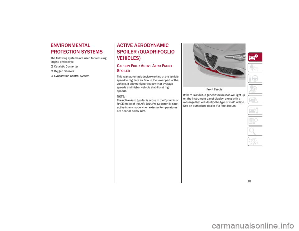
This is an automatic device working at the vehicle
speed to regulate air flow in the lower part of the
vehicle. It allows higher reactivity at average
speeds and higher vehicle stability at high
speeds.
NOTE:
The Active Aero Spoiler is active in the Dynamic or
RACE mode of the Alfa DNA Pro Selector; it is not
active in any mode when external temperatures
are near or below zero. Front Fascia
If there is a fault, a generic failure icon will light up
on the instrument panel display, along with a
message that will identify the type of malfunction.
See an authorized dealer if a fault occurs.
23_GA_OM_EN_USC_t.book Page 63
Page 66 of 248
64
GETTING TO KNOW YOUR INSTRUMENT PANEL
This section gives you all the information you need to understand and use the instrument panel correctly.
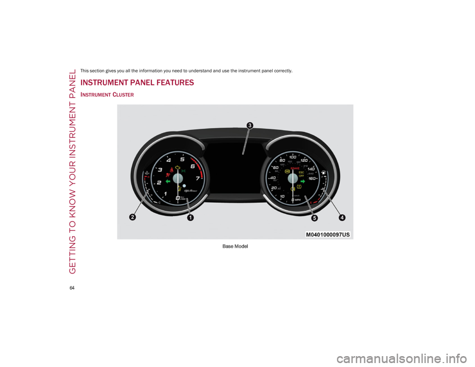
INSTRUMENT PANEL FEATURES
INSTRUMENT CLUSTER
Base Model
23_GA_OM_EN_USC_t.book Page 64
Page 67 of 248
65
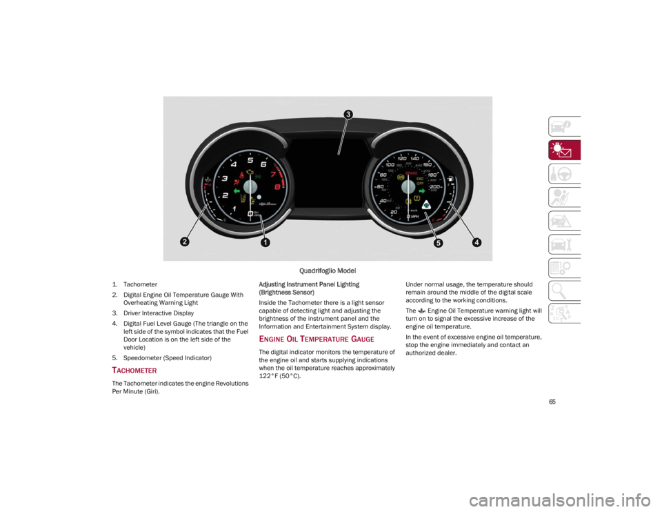
Quadrifoglio Model
1. Tachometer
2. Digital Engine Oil Temperature Gauge With Overheating Warning Light
3. Driver Interactive Display
4. Digital Fuel Level Gauge (The triangle on the left side of the symbol indicates that the Fuel
Door Location is on the left side of the
vehicle)
5. Speedometer (Speed Indicator)
TACHOMETER
The Tachometer indicates the engine Revolutions
Per Minute (Giri). Adjusting Instrument Panel Lighting
(Brightness Sensor)
Inside the Tachometer there is a light sensor
capable of detecting light and adjusting the
brightness of the instrument panel and the
Information and Entertainment System display.
ENGINE OIL TEMPERATURE GAUGE
The digital indicator monitors the temperature of
the engine oil and starts supplying indications
when the oil temperature reaches approximately
122°F (50°C).
Under normal usage, the temperature should
remain around the middle of the digital scale
according to the working conditions.
The Engine Oil Temperature warning light will
turn on to signal the excessive increase of the
engine oil temperature.
In the event of excessive engine oil temperature,
stop the engine immediately and contact an
authorized dealer.
23_GA_OM_EN_USC_t.book Page 65
Page 68 of 248
GETTING TO KNOW YOUR INSTRUMENT PANEL
66
FUEL LEVEL GAUGE
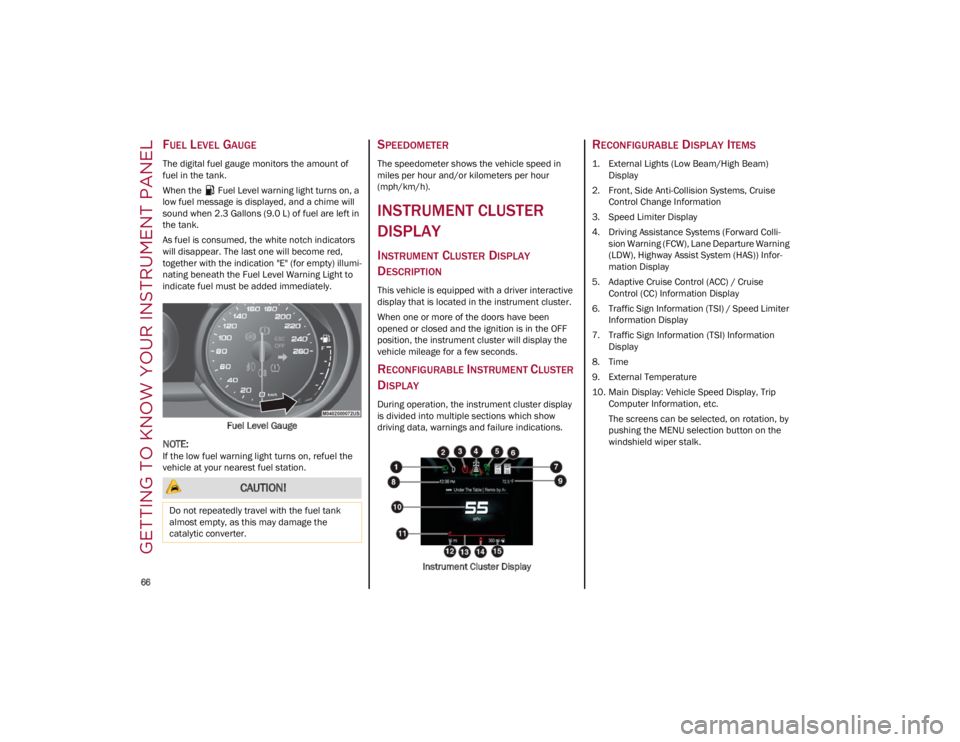
The digital fuel gauge monitors the amount of
fuel in the tank.
When the Fuel Level warning light turns on, a
low fuel message is displayed, and a chime will
sound when 2.3 Gallons (9.0 L) of fuel are left in
the tank.
As fuel is consumed, the white notch indicators
will disappear. The last one will become red,
together with the indication "E" (for empty) illumi-
nating beneath the Fuel Level Warning Light to
indicate fuel must be added immediately.
Fuel Level Gauge
NOTE:
If the low fuel warning light turns on, refuel the
vehicle at your nearest fuel station.
SPEEDOMETER
The speedometer shows the vehicle speed in
miles per hour and/or kilometers per hour
(mph/km/h).
INSTRUMENT CLUSTER
DISPLAY
INSTRUMENT CLUSTER DISPLAY
D
ESCRIPTION
This vehicle is equipped with a driver interactive
display that is located in the instrument cluster.
When one or more of the doors have been
opened or closed and the ignition is in the OFF
position, the instrument cluster will display the
vehicle mileage for a few seconds.
RECONFIGURABLE INSTRUMENT CLUSTER
D
ISPLAY
During operation, the instrument cluster display
is divided into multiple sections which show
driving data, warnings and failure indications.
Instrument Cluster Display
RECONFIGURABLE DISPLAY ITEMS
1. External Lights (Low Beam/High Beam)Display
2. Front, Side Anti-Collision Systems, Cruise Control Change Information
3. Speed Limiter Display
4. Driving Assistance Systems (Forward Colli -
sion Warning (FCW), Lane Departure Warning
(LDW), Highway Assist System (HAS)) Infor -
mation Display
5. Adaptive Cruise Control (ACC) / Cruise Control (CC) Information Display
6. Traffic Sign Information (TSI) / Speed Limiter Information Display
7. Traffic Sign Information (TSI) Information Display
8. Time
9. External Temperature
10. Main Display: Vehicle Speed Display, Trip Computer Information, etc.
The screens can be selected, on rotation, by
pushing the MENU selection button on the
windshield wiper stalk.
CAUTION!
Do not repeatedly travel with the fuel tank
almost empty, as this may damage the
catalytic converter.
23_GA_OM_EN_USC_t.book Page 66
Page 69 of 248
67
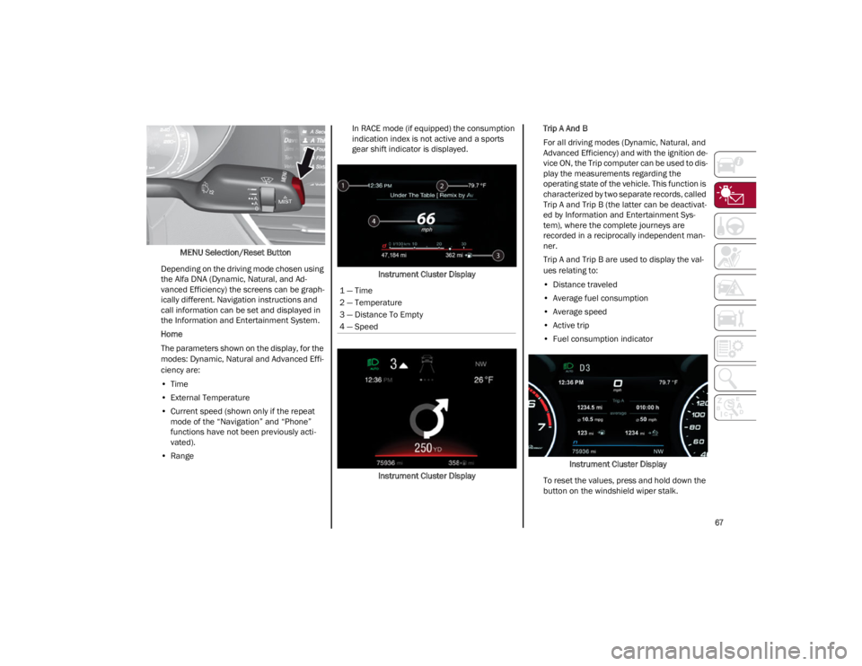
MENU Selection/Reset Button
Depending on the driving mode chosen using
the Alfa DNA (Dynamic, Natural, and Ad -
vanced Efficiency) the screens can be graph -
ically different. Navigation instructions and
call information can be set and displayed in
the Information and Entertainment System.
Home
The parameters shown on the display, for the
modes: Dynamic, Natural and Advanced Effi -
ciency are:
• Time
• External Temperature
• Current speed (shown only if the repeat
mode of the “Navigation” and “Phone”
functions have not been previously acti-vated).
• Range In RACE mode (if equipped) the consumption
indication index is not active and a sports
gear shift indicator is displayed.
Instrument Cluster Display
Instrument Cluster Display Trip A And B
For all driving modes (Dynamic, Natural, and
Advanced Efficiency) and with the ignition de
-
vice ON, the Trip computer can be used to dis -
play the measurements regarding the
operating state of the vehicle. This function is
characterized by two separate records, called
Trip A and Trip B (the latter can be deactivat -
ed by Information and Entertainment Sys -
tem), where the complete journeys are
recorded in a reciprocally independent man -
ner.
Trip A and Trip B are used to display the val -
ues relating to:
• Distance traveled
• Average fuel consumption
• Average speed
• Active trip
• Fuel consumption indicator
Instrument Cluster Display
To reset the values, press and hold down the
button on the windshield wiper stalk.
1 — Time
2 — Temperature
3 — Distance To Empty
4 — Speed
23_GA_OM_EN_USC_t.book Page 67
Page 70 of 248
GETTING TO KNOW YOUR INSTRUMENT PANEL
68
Performance
The displayed parameters differ according to
the active mode. The modes which can be se-
lected using the Alfa DNA system are:
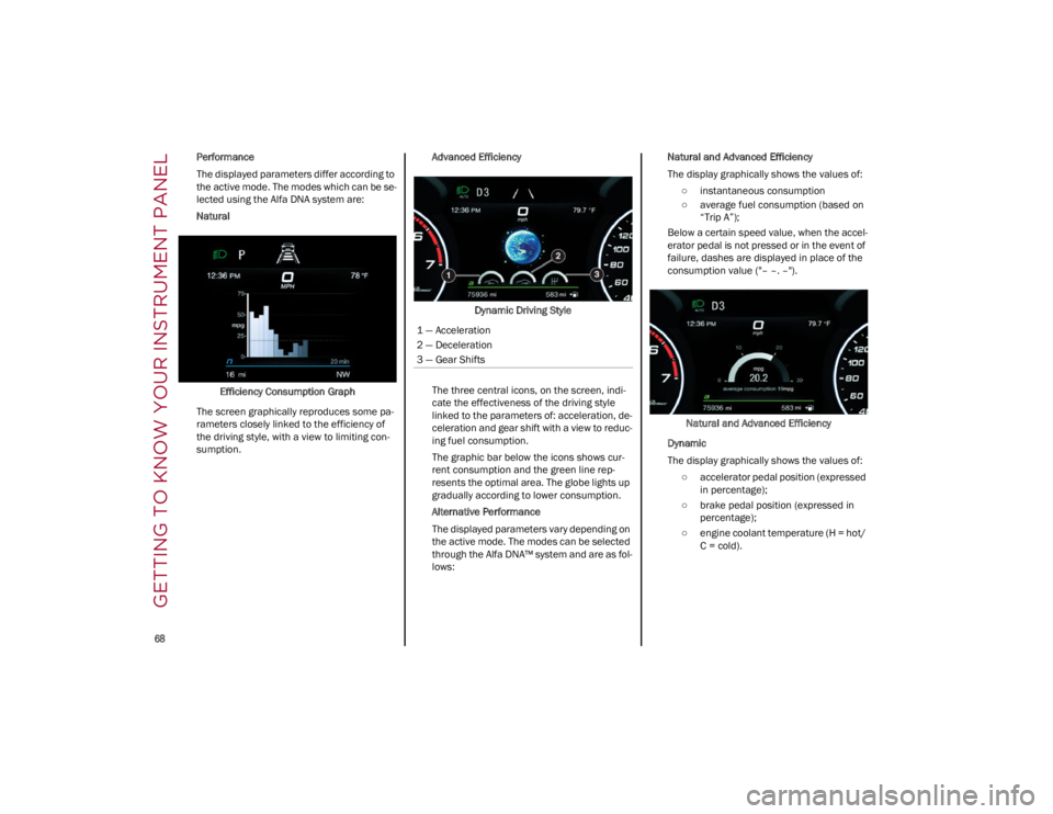
Natural
Efficiency Consumption Graph
The screen graphically reproduces some pa -
rameters closely linked to the efficiency of
the driving style, with a view to limiting con -
sumption. Advanced Efficiency
Dynamic Driving Style
The three central icons, on the screen, indi -
cate the effectiveness of the driving style
linked to the parameters of: acceleration, de -
celeration and gear shift with a view to reduc -
ing fuel consumption.
The graphic bar below the icons shows cur -
rent consumption and the green line rep -
resents the optimal area. The globe lights up
gradually according to lower consumption.
Alternative Performance
The displayed parameters vary depending on
the active mode. The modes can be selected
through the Alfa DNA™ system and are as fol -
lows: Natural and Advanced Efficiency
The display graphically shows the values of:
○ instantaneous consumption
○ average fuel consumption (based on “Trip A”);
Below a certain speed value, when the accel -
erator pedal is not pressed or in the event of
failure, dashes are displayed in place of the
consumption value ("– –. –").
Natural and Advanced Efficiency
Dynamic
The display graphically shows the values of: ○ accelerator pedal position (expressed in percentage);
○ brake pedal position (expressed in percentage);
○ engine coolant temperature (H = hot/ C = cold).
1 — Acceleration
2 — Deceleration
3 — Gear Shifts
23_GA_OM_EN_USC_t.book Page 68