ASTON MARTIN V8 VANTAGE 2010 Workshop Manual
Manufacturer: ASTON MARTIN, Model Year: 2010, Model line: V8 VANTAGE, Model: ASTON MARTIN V8 VANTAGE 2010Pages: 947, PDF Size: 43.21 MB
Page 131 of 947
Wipers and Washer System (01.16)
Body System (01.00)
Issue 4, November, 2008 Workshop Manual 1-11-1
Body System (01.00)
Wipers and Washer System (01.16)
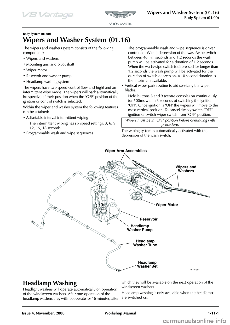
The wipers and washers system consists of the following
components:
• Wipers and washers
• Mounting arm and pivot shaft
•Wiper motor
• Reservoir and washer pump
• Headlamp washing system
The wipers have two speed control (low and high) and an
intermittent wipe mode. The wi pers will park automatically
irrespective of their position when the ‘OFF’ position of the
ignition or control switch is selected.
Within the wiper and washer sy stem the following features
can be attained:
• Adjustable interval intermittent wiping
The intermittent wiping has six speed settings, 3, 6, 9,
12, 15, 18 seconds.
• Programmable wash and wipe sequences The programmable wash and wipe sequence is driver
controlled. With a depression of the wash/wipe switch
between 40 milliseconds and 1.2 seconds the wash
pump will be activated for a duration of 1.2 seconds.
When the wash/wipe switch is depressed for longer than
1.2 seconds the wash pump will be activated for the
duration of switch depression
, a 10 second duration is
the maximum available.
• Vertical wiper park routine to aid servicing the wiper blades.
Hold buttons 8 and 9 (centre console) on continuously
for 500ms within 3 seconds of switching the ignition
‘ON’. Once ignition is ‘ON’ the wipers will move to the
most vertical position. To cancel simply switch ‘OFF’
ignition or switch wiper switch from ‘OFF’ position.
The wiping system is automatically activated with the
depression of the wash switch.
Headlamp Washing
Headlight washers will operate automatically on operation
of the windscreen washers. After one operation of the
headlamp washers they will not operate for 16 minutes, after which they will be available on the next operation of the
windscreen washers.
Headlamp washing is only available when the headlamps
are switched on.Wipers must be in ‘OFF’ pos
ition before continuing with
procedure.
Wiper Motor Wipers and
Washers
Wiper Arm Assemblies
Reservoir
Headlamp
Washer Pump
Headlamp
Washer Jet
Headlamp
Washer Tube
01-16-001
Page 132 of 947
Wipers and Washer System (01.16)
Body System (01.00)1-11-2 Workshop Manual Issue 4,November, 2008
Specifications
Maintenance
Windscreen Wiper Motor Assembly -
Renew
Removal
1. Remove wiper linkage.
2. Remove arm from motor (nut x1).
3. Remove motor from plate (bolts x3).
Installation
1. Install motor to plate (bolts x3).
2. Ensure wiper motor is in the ‘PARK’ position.
3. Install arm from motor (nut x1), using special tool.
4. Install wiper linkage.
Wiper Linkage Assembly - Renew
Removal
1. Remove brake booster (see Workshop Manual procedure 06.07.DE/06.07.DG Master Cylinder and
Vacuum Booster - Brake - Renew).
2. Remove inlet manifold (see Workshop Manual procedure 03.01.BB/03.01.BF Gasket - Manifold
Assembly - Intake Upper - Renew).
3. Remove wiper arm drivers si de (see Workshop Manual
procedure 01.16.AD Arm Asse mbly - Wiper - Driver -
Renew).
4. Remove wiper arm passengers side (see Workshop Manual procedure 01.16.AE Arm Assembly - Wiper -
Passenger - Renew).
5. Unclip expansion tank hose for access. 6. Remove sound deadening (trim buttons x6).
7. Remove seal from spindle.
8. Remove nuts (x2) from heatshield to move aside.
9. Unclip wiper motor harness (x2) LHS.
10. Unclip windscreen heater harness RHS.
11. Disconnect motor multiplu
g and unclip harness (x2).
12. To prevent damage, protect A/C pipe with tape before
wiper linkage removal.
13. Remove plate securing scre ws (x10) (through plenum).
14. Remove plate securing bolts (x8) (under bonnet).
15. Remove wiper linkage.
Installation
1. Install wiper linkage.
2. Install plate securing bolts (x8) (under bonnet).
3. Install plate securing scre ws (x10) (through scuttle
panel).
4. Connect motor multiplug and clip harness (x2).
5. Clip harness LHS.
6. Clip harness RHS.
7. Refit heatshield and install nuts (x2).
8. Install seal to spindle.
9. Install sound deadening (re-stick, trim buttons x6).
10. Clip expansion tank hose.
11. Install wiper arm drivers side (see Workshop Manual procedure 01.16.AD Arm Assembly - Wiper - Driver -
Renew).
12. Install wiper arm passengers side (see Workshop Manual
procedure 01.16.AE Arm Asse mbly - Wiper - Passenger
- Renew).
13. Install inlet manifold (see Workshop Manual procedure 03.01.BB/03.01.BF Gasket - Manifold Assembly - Intake
Upper - Renew).
14. Install brake booster (see Workshop Manual procedure 06.07.DE/06.07.DG Master Cylinder and Vacuum
Booster - Brake - Renew).
Windshield Wash Tube - Renew
Removal
1. Remove RH wheel arch liner (see Workshop Manual Procedure 01.02.GB Wheel Arch Liner - Front - RH -
Renew).
2. Place container to catch fluid.
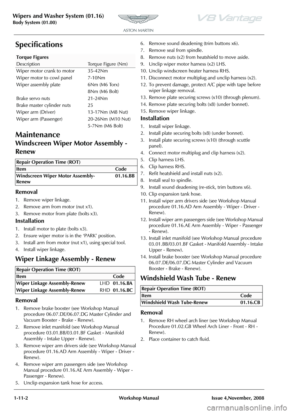
Torque Figures
DescriptionTorque Figure (Nm)
Wiper motor crank to motor 35-42Nm
Wiper motor to cowl panel 7-10Nm
Wiper assembly plate 6Nm (M6 Torx) 8Nm (M6 Bolt)
Brake servo nuts 21-24Nm
Brake master cylinder nuts 25
Wiper arm (Driver) 13-17Nm (M8 Nut)
Wiper arm (Passenger) 20-26Nm (M10 Nut) 5-7Nm (M6 Bolt)
Repair Operation Time (ROT)
Repair Operation Time (ROT)
Repair Operation Time (ROT)
ItemCode
Windshield Wash Tube-Renew 01.16.CB
Page 133 of 947
Wipers and Washer System (01.16)
Body System (01.00)
Issue 4, November, 2008 Workshop Manual 1-11-3
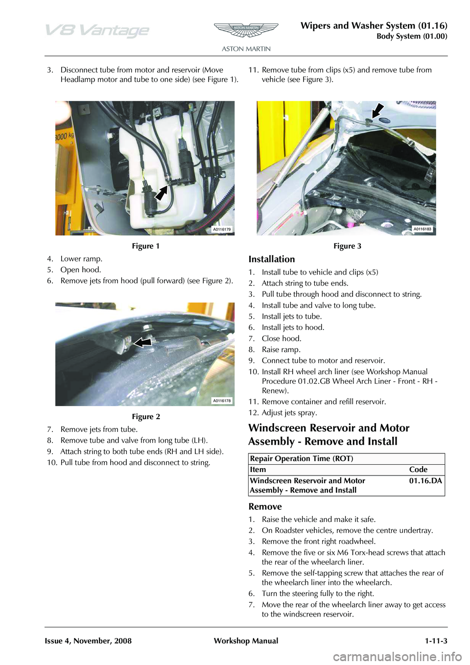
3. Disconnect tube from motor and reservoir (Move Headlamp motor and tube to one side) (see Figure 1).
4. Lower ramp.
5. Open hood.
6. Remove jets from hood (pull forward) (see Figure 2).
7. Remove jets from tube.
8. Remove tube and valve from long tube (LH).
9. Attach string to both tube ends (RH and LH side).
10. Pull tube from hood and disconnect to string. 11. Remove tube from clips (x5) and remove tube from
vehicle (see Figure 3).
Installation
1. Install tube to vehicle and clips (x5)
2. Attach string to tube ends.
3. Pull tube through hood and disconnect to string.
4. Install tube and valve to long tube.
5. Install jets to tube.
6. Install jets to hood.
7. Close hood.
8. Raise ramp.
9. Connect tube to motor and reservoir.
10. Install RH wheel arch liner (see Workshop Manual Procedure 01.02.GB Wheel Arch Liner - Front - RH -
Renew).
11. Remove container and refill reservoir.
12. Adjust jets spray.
Windscreen Reservoir and Motor
Assembly - Remove and Install
Remove
1. Raise the vehicle and make it safe.
2. On Roadster vehicles, re move the centre undertray.
3. Remove the front right roadwheel.
4. Remove the five or six M6 Torx-head screws that attach the rear of the wheelarch liner.
5. Remove the self-tapping screw that attaches the rear of the wheelarch liner into the wheelarch.
6. Turn the steering fully to the right.
7. Move the rear of the wheelarch liner away to get access to the windscreen reservoir.
Figure 1
Figure 2
A0116179
A0116178
Figure 3
Repair Operation Time (ROT)
A0116183
Page 134 of 947
Wipers and Washer System (01.16)
Body System (01.00)1-11-4 Workshop Manual Issue 4,November, 2008
8. Disconnect the windscreen washer pipe and drain the reservoir into an applicable container.
9. Disconnect the two clips that attach the battery harness to the bottom of the reservoir.
10. Move the harness away.
11. Disconnect the clip that attaches the harness for the level sensor to the reservoir.
12. Remove the rear bottom reservoir fixing.
13. Lower the vehicle on the lift.
14. Disconnect the electrical connector for the windscreen washer motor.
15. Release the headlamp washer pipe from the clip and turn the motor to disconnect the pipe (quickfit) and the
electrical connector.
16. Release the windscreen washer pipe from the reservoir.
17. Remove the two reservoir attachment screws.
18. Let the reservoir fall, then release the filler tube from the clip.
19. Move the reservoir down and forward to get access.
20. Disconnect the electrical connector from the level sensor.
Install
1. Connect the electrical connector to the level sensor.
2. Move the reservoir into position.
3. Install the filler pipe into the clip.
4. Install the three attachment screws.
5. Install the windscreen washer pipe into clips on the reservoir and connect it to the motor.
6. Install the headlamp washer pipe. Connect the pipe to the pump.
7. Connect the electrical connector to the pump.
8. Connect the electrical co nnector for the windscreen
washer motor.
9. Raise the vehicle on the lift.
10. Connect the clip that attach es the level sensor harness to
the reservoir.
11. Connect the two clips that attach the battery harness to bottom of the reservoir.
12. Put the wheelarch liner back into position.
13. Turn the steering to the centre position.
14. Install the self-tapping screw that attaches the rear of the wheelarch liner into the wheelarch.
15. Install the five or six M6 Torx-head screws that attach the rear of the wheelarch liner.
16. Install the front right roadwheel.
17. On Roadster vehicles, in stall the centre undertray.
18. Lower the vehicle.
19. Fill the washer reservoir.
Low Level Water Sensor - Remove and
Install
Remove
1. Raise the vehicle and make it safe.
2. On Roadster vehicles, remove the centre undertray.
3. Remove the front right roadwheel.
4. Remove the five or six M6 Torx-head screws that attach the rear of the wheelarch liner.
5. Remove the self-tapping screw that attaches the rear of the wheelarch liner into the wheelarch.
6. Turn the steering fully to the right.
7. Move the rear of the wheelarch liner away to get access to the windscreen reservoir.
8. Disconnect the windscreen washer pipe and drain the reservoir into an applicable container.
9. Disconnect the two clips that attach the battery harness to the bottom of the reservoir.
10. Move the harness away.
11. Disconnect the clip that attaches the level sensor harness to the reservoir.
12. Remove the rear-lower reservoir fixing.
13. Lower the vehicle on the lift.
14. Disconnect the electrical connector from the windscreen washer motor.
15. Unclip headlamp washer pipe and turn motor to disconnect pipe (quickfit) and multiplug.
16. Unclip the windscreen washer pipe from the reservoir.
17. Remove the two reservoir attachment screws.
18. Let the reservoir fall, then release the filler tube from the
clip.
19. Move the reservoir down and forward to give access.
20. Disconnect the electrical connector for the level sensor.
21. Remove level sensor and seal from reservoir.
Install
1. Install the level sensor and seal in the reservoir.
2. Connect the electrical connector for the level sensor
3. Move the reservoir into position.
4. Install the filler pipe in the clip.
5. Install the three attachment screws.
6. Clip the windscreen washer pipe into reservoir and install it onto the motor.
7. Clip the headlamp washer pipe, connect the pipe
(quickfit) and the electrical connector.
8. Connect windscreen washer motor multiplug.
9. Raise ramp.
10. Connect the clip that attaches the level sensor harness to the reservoir.
Repair Operation Time (ROT)
ItemCode
Low Level Water Sensor - Remove and
Install 01.16.DC
Page 135 of 947
Wipers and Washer System (01.16)
Body System (01.00)
Issue 4, November, 2008 Workshop Manual 1-11-5
11. Connect the two clips that attach the battery harness to the bottom of the reservoir.
12. PPut the wheelarch liner back into position.
13. Turn the steering to the centre position.
14. Install the self-tapping screw that attaches the rear of the wheelarch liner into the wheelarch.
15. Install the five or six M6 Torx-head screws that attach
the rear of the wheelarch liner.
16. Install the front right roadwheel.
17. On Roadster vehicles, in stall the centre undertray.
18. Lower the vehicle.
19. Fill the washer reservoir.
Headlamp Wash Motor and Pump
Assembly - Renew
Removal
1. Raise the vehicle and make it safe.
2. On Roadster vehicles, re move the centre undertray.
3. Remove the front right roadwheel.
4. Remove the five or six M6 Torx-head screws that attach the rear of the wheelarch liner.
5. Remove the self-tapping screw that attaches the rear of the wheelarch liner into the wheelarch.
6. Turn the steering fully to the right.
7. Move the rear of the wheela rch liner away to get access
to the windscreen reservoir.
8. Disconnect the windscreen washer pipe and drain the reservoir into an applicable container.
9. Disconnect the two clipsthat attach the battery harness to the bottom of the reservoir. Move the harness away.
10. Disconnect the clip that attaches the harness for the
level sensor to the reservoir.
11. Remove the rear-lower reservoir fixing.
12. Lower the vehicle on the lift.
13. Disconnect the electrical connector for the windscreen
washer motor.
14. Release the headlamp washer pipe and turn the motor to disconnect the pipe (quickfit) and the electrical
connector.
15. Release the windscreen washer pipe from the reservoir.
16. Remove the two reservoir attachment screws.
17. Let the reservoir fall, then release the filler tube from the clip.
18. Move the reservoir down and forward to give access.
19. Disconnect the electrical co nnector for the level sensor.
20. Remove the headlamp washer motor, seal and support clip from reservoir.
Installation
1. Install the headlamp washer motor, seal and support clip into the reservoir.
2. Connect the electrical connector for the level sensor.
3. Move the reservoir into position.
4. Connect the filler pipe and install the clip.
5. Install the three attachment screws.
6. Clip the windscreen washer pipe into reservoir and connect it to the motor.
7. Install the headlamp washer pipe in position. Connect
the pipe (quickfit) and the electrical connector.
8. Connect the electrical connector for the windscreen washer motor.
9. Raise ramp.
10. Connect the clip that attaches the level sensor harness to the reservoir.
11. Connect the two clips that attach the battery harness to the bottom of the reservoir.
12. Put the wheelarch liner back into position.
13. Turn the steering to the centre position.
14. Install the self-tapping screw that attaches the rear of the wheelarch liner into the wheelarch.
15. Install the five or six M6 Torx-head screws that attach the rear of the wheelarch liner.
16. Install the front right roadwheel.
17. On Roadster vehicles, install the centre undertray.
18. lower the vehicle.
19. Fill washer reservoir.
Headlamp Wash Tube Assembly - Renew
Removal
1. Remove LH headlamp (see Workshop Manual procedure 17.01.AB Headlamp Assembly - LH -
Renew).
2. Remove RH headlamp (see Workshop Manual procedure 17.01.BB Headlamp Assembly - RH -
Renew).
3. Place container to catch fluid.
Repair Operation Time (ROT)
Repair Operation Time (ROT)
Page 136 of 947
Wipers and Washer System (01.16)
Body System (01.00)1-11-6 Workshop Manual Issue 4,November, 2008
4. Remove tube from motor (quickfit) and reservoir (see Figure 1).
5. Remove tube from body (c lips x2) (see Figure 2).
6. Lower ramp.
7. Open hood.
8. Remove slam panel. 9. Remove tube from clips (x9) and remove tube from
vehicle (see Figure 3).
Installation
1. Install tube to vehicle and clips.
2. Install slam panel.
3. Close hood.
4. Raise ramp.
5. Install tube to body (clips x2).
6. Install tube to motor (quickfit) and reservoir.
7. Install LH headlamp (see Workshop Manual procedure 17.01.AB Headlamp As sembly - LH - Renew).
8. Install RH headlamp (see Workshop Manual procedure
17.01.BB Headlamp Assembly - RH - Renew).
9. Remove container and refill reservoir.
10. Adjust jets spray.
Washer Fluid Reservoir - Renew
Removal
1. Remove RH wheel arch liner (see Workshop Manual procedure 01.02.GB Wheel Arch Liner - Front - RH -
Renew).
2. Disconnect Windscreen wash er pipe to drain reservoir
into suitable container.
3. Disconnect clips (x2) securing battery harness to bottom of reservoir (move aside).
4. Disconnect clip (x1) securi ng level sensor harness to
reservoir.
5. Remove rear lower reservoir fixing.
6. Lower ramp.
7. Disconnect windscreen washer motor multiplug.
8. Unclip Headlamp washer pipe and turn motor to disconnect pipe (quickfit) and multiplug.
9. Unclip windscreen washer pipe from reservoir.
Figure 1
Figure 2
A0116179
A0116189
Figure 3
Repair Operation Time (ROT)
ItemCode
Washer Fluid Reservoir-Renew 01.16.FB
A0116190
Page 137 of 947

Wipers and Washer System (01.16)
Body System (01.00)
Issue 4, November, 2008 Workshop Manual 1-11-7
10. Remove reservoir retaining screws (x2).
11. Allow reservoir to drop, then disconnect filler tube (clip
x1).
12. Manoeuvre reservoir down and forward to access, disconnect level sensor multiplug.
13. Remove level sensor an d seal from reservoir.
14. Remove windscreen washer motor and seal from reservoir.
15. Remove headlamp washer motor and seal and support clip from reservoir.
Installation
1. Install headlamp Washer motor and seal and support clip to reservoir.
2. Install windscreen washer motor and seal to reservoir.
3. Install level sensor and seal to reservoir.
4. Connect level sensor multip lug and manoeuvre reservoir
into position.
5. Connect filler pipe (clip x1).
6. Install fixing screws (x3).
7. Clip windscreen washer pipe into reservoir and install to motor.
8. Clip headlamp washer pipe, connect pipe (quickfit) and
multiplug.
9. Connect windscreen washer motor multiplug.
10. Raise ramp.
11. Connect clip (x1) securi ng level sensor harness to
reservoir.
12. Connect clips (x2) securing battery harness to bottom of reservoir.
13. Remove RH wheel arch liner (see Workshop Manual procedure 01.02.GB Wheel Arch Liner - Front - RH -
Renew).
14. Fill washer reservoir.
Page 138 of 947

Wipers and Washer System (01.16)
Body System (01.00)1-11-8 Workshop Manual Issue 4,November, 2008
Page 139 of 947

Convertible Roof (01.17)
Body System (01.00)
May 2007 Workshop Manual 1-12-1
Body System (01.00)
Convertible Roof and Roof Opening Subsystem (01.17)
System Description
The convertible roof system comprises of an electrically dr iven hydraulic pump and six hydraulic rams. Four rams raise
and lower the roof and two raise and lower the tonneau cover. The pump is powered via either the 'Hydraulic Pump Fluid
In' or 'Hydraulic Pump Fluid Out' relay and is instructed vi a the Convertible Roof Module (CRM). The CRM is activated by
the Console mounted Roof Switch. A further module controls the position and drive command for the Tonneau Latches.
The roof hydraulic pump is protected by a 30A fuse. During Roof Operation the door glass and boot release commands
are also controlled by the CRM.
Page 140 of 947
Convertible Roof (01.17)
Body System (01.00)1-12-2 Workshop Manual May 2007
Maintenance
Hood Assembly-Renew
Removal
1. Remove Tonneau well liner (see Workshop Manual procedure 01.17.DB Tonneau Well Liner - Renew).
2. Remove Panel assembly body side LH (see Workshop
Manual procedure 01.05.DY Panel Assembly - Bodyside
Trim - Rear - LH - Renew).
3. Remove Panel assembly body side RH (see Workshop Manual procedure 01.05.DX Panel Assembly - Bodyside
Trim - Rear - RH - Renew).
4. Remove Tonneau cover (see Workshop Manual procedure 01.17.CA Cover - Tonneau - Renew).
5. Disconnect vehicle battery. 6. Release both tonneau cylinders lower retaining clips and
disconnect cylinders from body (see Figure 1).
7. Remove tonneau cylinder pivot bracket from body (bolts x3) (see Figure 2).
WAR NI NG
MANY OF THE FOLLOWING PROCEDURES ADVISE
OPERATING THE ROOF TO THE HALFWAY POSITION.
WHEN THE OPERATION OF THE ROOF IS STOPPED
MID-CYCLE, WITH THE TO NNEAU UP, ANY LOSS OF
POWER (I.E. REMOVING THE VEHICLE KEY OR AFTER
10 MINUTES OF IDLE) WILL RESULT IN THE
HYDRAULIC PRESSURE DROPPING AND MAY CAUSE
A CLASH SCENARIO.
WHEN ADVISED TO OPEN THE ROOF TO THE
HALFWAY POSITION, ALWA YS SECURE THE ROOF
WITH STRAPS AND PROPS (AS ADVISED). SHOULD
THE ROOF CLASH AND THEN POWER BE RETURNED
TO THE VEHICLE SEVERE DAMAGE TO THE ROOF
WILL RESULT.
TO RECTIFY THE ‘CLASH’ SCENARIO FOLLOW THE
PROCEDURE BELOW:
1. ENSURE IGNITION IS OFF AND REMOVE KEY.
2. MANUALLY RAISE TONNEAU LID.
3. WHILST TONNEAU IS RAISED, FULLY RETRACT
ROOF ALLOWING IT TO SETTLE BACK INTO
TONNEAU WELL.
4. ENSURE LID CLEARS TONNEAU STRIKERS DURING
MOVEMENT.
5. CLOSE TONNEAU LID (ALLOW TO DROP UNDER
OWN WEIGHT).
6. ONCE TONNEAU IS CLOSED TURN ON IGNITION
AND FULLY RETRACT ROOF INTO TONNEAU WELL
AND LATCH TONNEAU.
7. ONCE MOVEMENT IS COMPLETED AND HOOD IS
STOWED FULL FUNCTIONALITY IS RESTORED.
Repair Operation Time (ROT)
Figure 1
Figure 2