ASTON MARTIN V8 VANTAGE 2010 Workshop Manual
Manufacturer: ASTON MARTIN, Model Year: 2010, Model line: V8 VANTAGE, Model: ASTON MARTIN V8 VANTAGE 2010Pages: 947, PDF Size: 43.21 MB
Page 161 of 947

Convertible Roof (01.17)
Body System (01.00)
May 2007 Workshop Manual 1-12-23
2. Align and install latching kit, secure with nuts and screw.
3. Attach tie rod, secure with C-clip.
4. Install right-hand header latch flex shaft (see Workshop Manual procedure 01.17.EG Flex Shaft - RH - Renew).
Convertible Roof Hydraulic Pump -
Check Fluid Level
Removal
1. Operate roof to halfway position with tonneau open. Support roof when hydrau lic pressure drops with
suitable straps and support tonneau cover with suitable
prop (see Figure 1). 2. Remove trim clip and releas
e tonneau lining stiffening
rod (see Figure 2).
3. Release velcro and move tonneau well liner aside to
expose lower cylinder fixing and pump casing.
4. Release cylinder lower retaining clip and disconnect cylinder from body (see Figure 3).
Repair Operation Time (ROT)
Figure 2
Figure 3
Page 162 of 947

Convertible Roof (01.17)
Body System (01.00)1-12-24 Workshop Manual May 2007
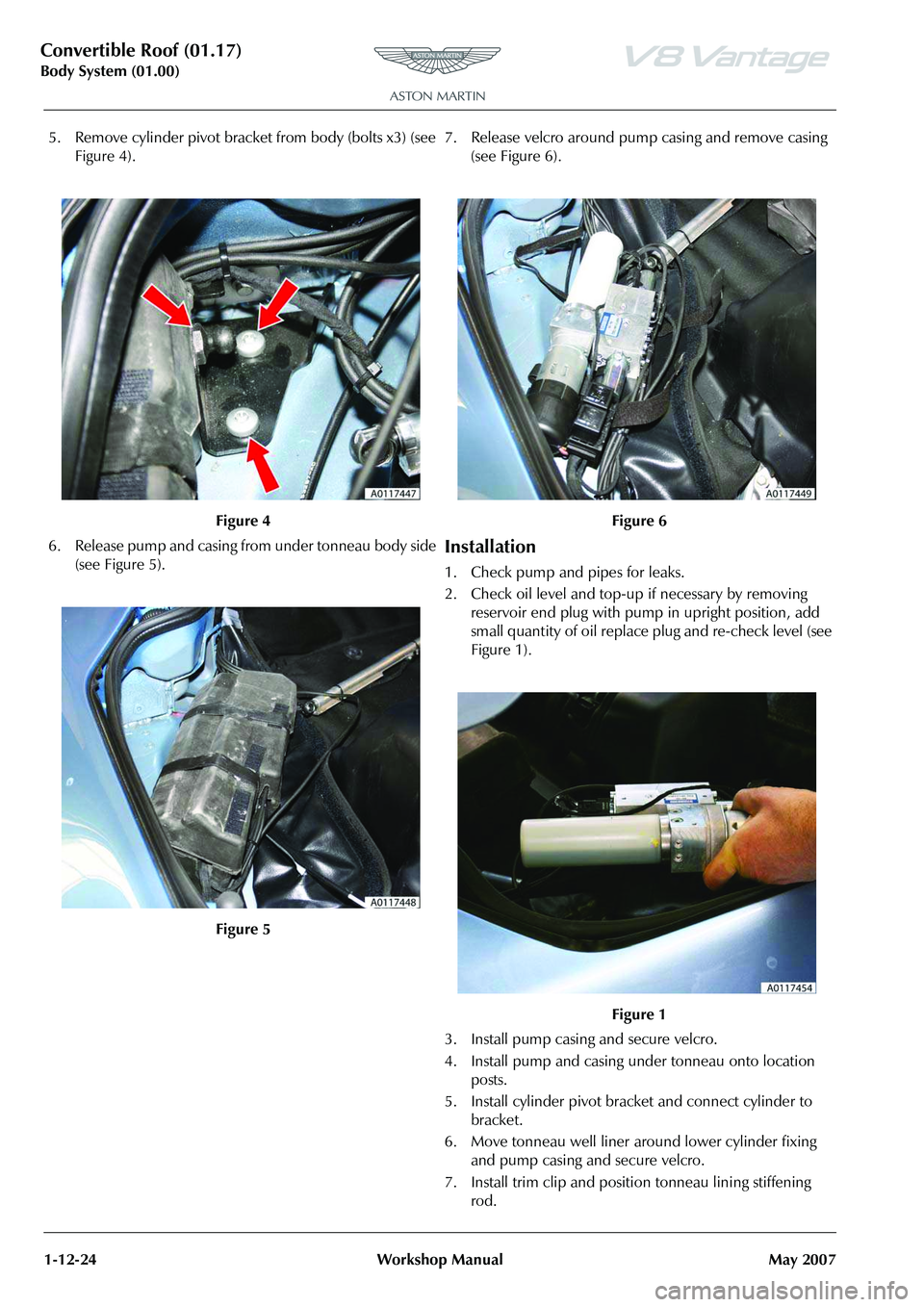
5. Remove cylinder pivot bracket from body (bolts x3) (see Figure 4).
6. Release pump and casing from under tonneau body side (see Figure 5). 7. Release velcro around pump casing and remove casing
(see Figure 6).
Installation
1. Check pump and pipes for leaks.
2. Check oil level and top-up if necessary by removing reservoir end plug with pump in upright position, add
small quantity of oil replace plug and re-check level (see
Figure 1).
3. Install pump casing and secure velcro.
4. Install pump and casing under tonneau onto location posts.
5. Install cylinder pivot bracket and connect cylinder to bracket.
6. Move tonneau well liner around lower cylinder fixing and pump casing and secure velcro.
7. Install trim clip and position tonneau lining stiffening rod.
Figure 4
Figure 5
Figure 6
Figure 1
Page 163 of 947

Convertible Roof (01.17)
Body System (01.00)
May 2007 Workshop Manual 1-12-25
8. Restore roof and tonneau to original position
Cantrail Cover Trim - Renew
Removal
1. Operate roof to halfway position and support roof when hydraulic pressure drops with suitable straps.
2. Remove Torx screws (x2) securing trim to hood
mechanism and release trim (see Figure 1). 3. Remove bolt securing tensio
n string to trim and remove
trim (see Figure 2).
Installation
1. Position tension string to trim and secure with screw.
2. Install trim to hood and secure with bolts (ensure tension string is positioned either side of rear screw).
3. Restore roof to original position.
B-Post Trim Cover - Renew
Removal
1. Remove cantrail trim (see Workshop Manual procedure 01.17.BT Cover - Trim - Cantrail - Renew).
2. Mark position of screws (x2) to aid installation.
Repair Operation Time (ROT)
Figure 2
Repair Operation Time (ROT)
Page 164 of 947

Convertible Roof (01.17)
Body System (01.00)1-12-26 Workshop Manual May 2007
3. Remove screws (x2) securing trim to hood mechanism and release trim (see Figure 1).
4. Unclip spring securing tension string to hood mechanism (see Figure 2). 5. Remove screw securing tension strap to hood
mechanism and remove trim (see Figure 3).
Installation
1. Pass tension strap through trim and secure to hood mechanism using bolt.
2. Pass tension string through trim and secure tension spring to hood mechanism.
3. Install trim to hood mechanism and secure with screws.
4. Install cantrail trim (see Workshop Manual procedure 01.17.BT Cover - Trim - Cantrail - Renew).
Figure 1
Figure 2
Figure 3
Page 165 of 947

Convertible Roof (01.17)
Body System (01.00)
May 2007 Workshop Manual 1-12-27
Tonneau Cover - Renew
Removal
1. Open trunk lid and loosen 2 tonneau hinge bolts (see Figure 1).
2. Protect tonneau cover and boot lid edges with suitable tape and close trunk lid.
3. Operate roof to halfway position and support roof when hydraulic pressure drops with suitable straps and
support tonneau cover with suit able prop (see Figure 2).4. Release upper spring clips se
curing tonneau cylinders to
tonneau cover and release cylinders (both sides) (see
Figure 3).
Repair Operation Time (ROT)
Figure 2
Figure 3
Page 166 of 947

Convertible Roof (01.17)
Body System (01.00)1-12-28 Workshop Manual May 2007
5. Release velcro and clip securing right-hand tonneau well liner edges (see Figure 4).
6. Release velcro and 3 clips securing left-hand tonneau well liner edges (see Figure 5). 7. Release tonneau B-post flap cables from hood linkage
(both sides) (see Figure 6).
8. With assistance, remove tonneau hinge bolts and
remove tonneau cover.
9. Release 2 clips (both sides) securing B-post flap cables to tonneau cover (see Figure 7).
10. Mark mounting position of B-post flaps (both sides).
Figure 4
Figure 5
Figure 6
Figure 7
Page 167 of 947

Convertible Roof (01.17)
Body System (01.00)
May 2007 Workshop Manual 1-12-29
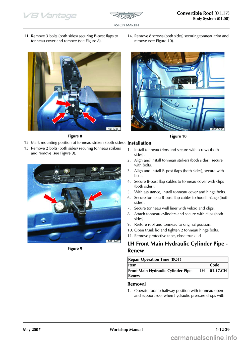
11. Remove 3 bolts (both sides) securing B-post flaps to tonneau cover and remove (see Figure 8).
12. Mark mounting position of tonneau strikers (both sides).
13. Remove 2 bolts (both sides) securing tonneau strikers and remove (see Figure 9). 14. Remove 8 screws (both sides
) securing tonneau trim and
remove (see Figure 10).
Installation
1. Install tonneau trims and secure with screws (both sides).
2. Align and install tonneau st rikers (both sides), secure
with bolts.
3. Align and install B-post flaps (both sides), secure with bolts.
4. Secure B-post flap cables to tonneau cover with clips (both sides).
5. With assistance, install tonneau cover and hinge bolts.
6. Secure tonneau B-post flap cables to hood linkage (both sides).
7. Secure tonneau well liner with velcro and clips.
8. Attach tonneau cylinders and secure with clips (both sides).
9. Restore roof and tonneau to original position.
10. Open trunk lid and tighten 2 tonneau hinge bolts.
11. Remove protective tape, close trunk lid
LH Front Main Hydraulic Cylinder Pipe -
Renew
Removal
1. Operate roof to halfway position with tonneau open and support roof when hydraulic pressure drops with
Figure 8
Figure 9
Figure 10
Repair Operation Time (ROT)
Page 168 of 947

Convertible Roof (01.17)
Body System (01.00)1-12-30 Workshop Manual May 2007
suitable straps and support tonneau cover with suitable
prop (see Figure 1).
2. Remove panel quarter trim lower (see Workshop Manual procedure 01.05.CR Panel Assembly - Quarter
Trim Lower - RH - Renew).
3. Disconnect battery.
4. Cut cable ties securing pipes and wires to cylinder (see Figure 2).
5. Release clips securing pipes to cylinder and disconnect pipes. 6. Release fir tree clip and cable
tie securing both pipes to
roof frame (remove pipes as pair).
7. Attach string to cylinder end of both pipes to aid
installation.
8. Feed pipes through to tonneau area by carefully guiding through roof mechanism and release string (see Figure
3).
9. Remove harness/pipe reta ining clips (x2) (LH) (see
Figure 4).
WAR NI NG
APPROXIMATELY 20 SECONDS AFTER THE OPEN/
CLOSE OPERATION HAS BEEN INTERRUPTED THE
ROOF MAY SUDDENLY DROP DUE TO LOSS OF
HYDRAULIC PRESSURE. IF THIS HAPPENS ENSURE NO
BODY PARTS ARE CLOSE TO THE ROOF MECHANISM.
IF THE ROOF REQUIRES MAINTENANCE, SUPPORT PROPERLY USING SUITABLE PROPS AND STRAPS.
Figure 1
Figure 2
Figure 3
Figure 4
Page 169 of 947

Convertible Roof (01.17)
Body System (01.00)
May 2007 Workshop Manual 1-12-31
10. Remove harness/pipe retain ing clips (x9) behind ROPS
units (see Figure 5).
11. Remove harness/pipe retaining clips (x3) LH side (see Figure 6). 12. Remove trim clip and releas
e tonneau lining stiffening
rod (see Figure 7).
13. Release velcro and move tonneau well liner aside to expose lower cylinder fixing and pump casing.
14. Release cylinder lower retaining clip and disconnect cylinder from body (see Figure 8).
15. Remove cylinder pivot brack et from body (bolts x3).
Figure 5
Figure 6
Figure 7
Figure 8
Page 170 of 947

Convertible Roof (01.17)
Body System (01.00)1-12-32 Workshop Manual May 2007
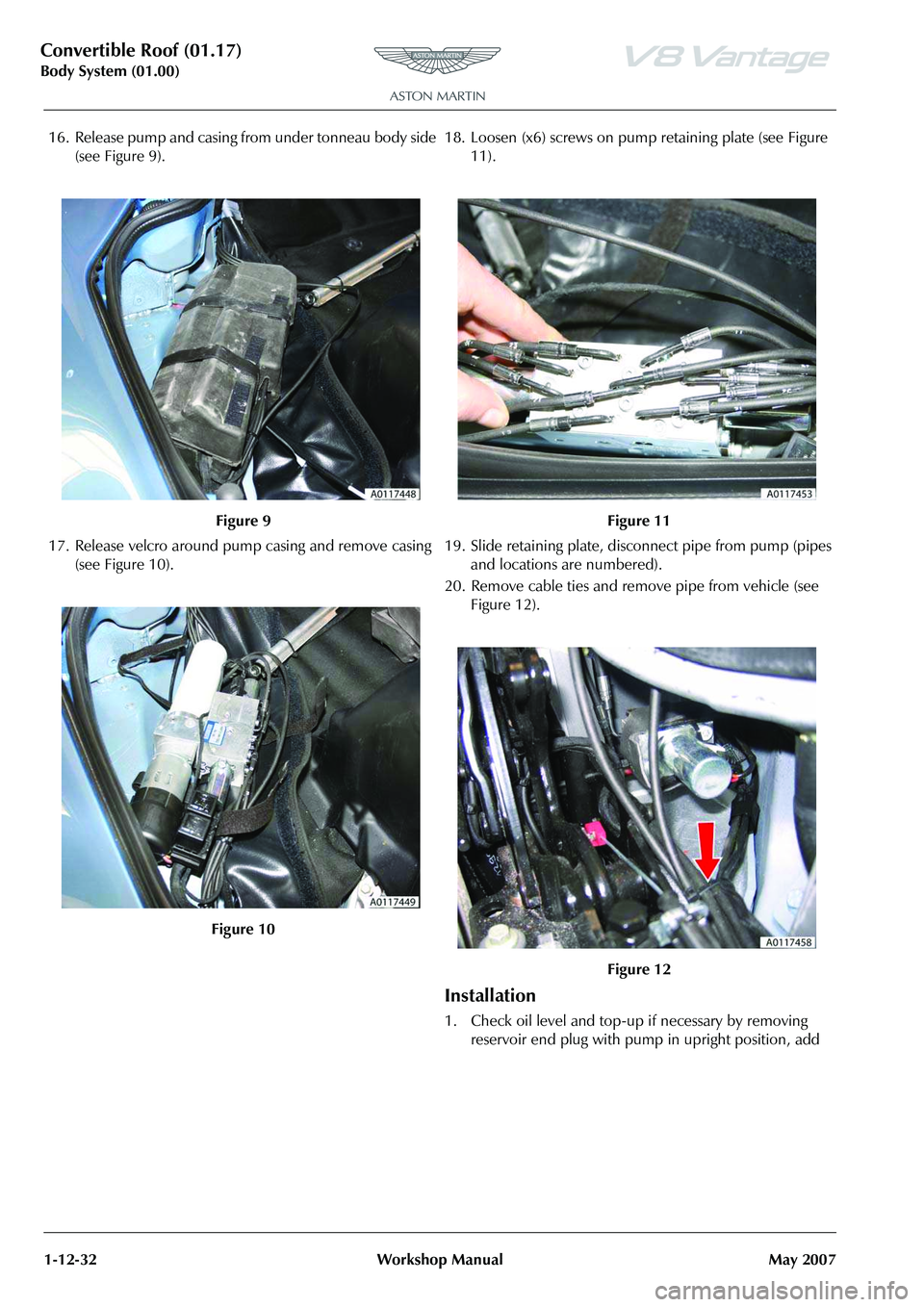
16. Release pump and casing from under tonneau body side (see Figure 9).
17. Release velcro around pu mp casing and remove casing
(see Figure 10). 18. Loosen (x6) screws on pump
retaining plate (see Figure
11).
19. Slide retaining plate, disconnect pipe from pump (pipes and locations are numbered).
20. Remove cable ties and remove pipe from vehicle (see Figure 12).
Installation
1. Check oil level and top-up if necessary by removing reservoir end plug with pump in upright position, add
Figure 9
Figure 10
Figure 11
Figure 12