torque ASTON MARTIN V8 VANTAGE 2010 Workshop Manual
[x] Cancel search | Manufacturer: ASTON MARTIN, Model Year: 2010, Model line: V8 VANTAGE, Model: ASTON MARTIN V8 VANTAGE 2010Pages: 947, PDF Size: 43.21 MB
Page 605 of 947
Power Steering (11.02)
Steering (11.00)11-2-2 Workshop Manual Issue 5, January 2010
Maintenance
Power Steering System - Bleed
Procedure
1. Do a check of the fluid level in the PAS fluid reservoir. Add fluid if necessary.
2. Start the engine and let it idle for 20 seconds.
3. Operate the steering fully to the left and then the right through three cycles.
4. Stop the engine.
5. Wait for five minutes then do a check of the fluid level in the PAS fluid reservoir again.
6. Add fluid if necessary.
7. Install the PAS fluid reservoir cap.
Power Steering Pump-Renew
Removal
1. Remove A/C compressor (see Workshop Manual procedure 03.05.BE Compre ssor - Air Conditioning -
Renew).
2. Coolant drain (see Workshop Manual procedure 03.03.AD Coolant - Drain & Refill).
3. Remove PAS fluid from reservoir.
4. Disconnect HP union from PAS pump pipe.
5. Remove bolt P-clip suction hose to body.
6. Remove bolt (x1) HP pump pipe to engine.
7. Remove bolts (x3) PAS pump to engine.
8. Disconnect bottom hose and move aside.
9. Unclip (x1) harness from cylinder head for access.
10. Manouvre pump forward and up.
11. Disconnect suction hose (cut off clip) and remove pump.
12. Remove HP union pipe from pump (mark position on
pump).
Installation
1. Install HP union pipe to pump (align correctly), fit new O-ring.
2. Install pump to vehicle connect suction pipe to PAS pump, align timing marks and fit new clip.
3. Manouvre pump into position.
4. Install bolts (x3) PAS pump to engine (torque).
5. Install bolt (x1) HP pump pipe to engine (torque).
6. Connect bottom hose.
7. Clip (x1) harness from cylinder head for access. 8. Install bolt P-clip suction hose to body (torque).
9. Connect HP union to PAS pump pipe, replace O-ring
(torque).
10. Coolant refill (see Workshop Manual procedure 03.03.AD Coolant - Drain & Refill).
11. Install A/C compressor (see Workshop Manual procedure 03.05.BE Compre ssor - Air Conditioning -
Renew).
12. Top-up PAS fluid.
13. Start and run engine, operate steering lock to lock x2.
14. Top-up PAS fluid.
Power Assisted Steering (PAS) Rack -
Remove and Install
Removal
1. Disconnect the battery ground cable.
2. Remove the front undertray (refer to Workshop Manual Procedure 01.02.NB - Front Undertray).
3. Remove the front wheels and tyres (refer to Workshop Manual Procedure 04.04.ED - Wheel and Tyre - Pair).
4. Remove the front right side wheel-arch liner (refer to Workshop Manual Procedure 01.02.GB - Front Right
Side Wheel-Arch Liner).
5. Put a container in position under the oil tank to collect oil.
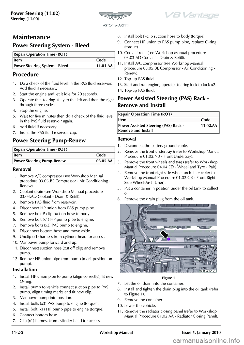
6. Remove the drain plug from the oil tank.
Figure 1
7. Let the oil drain into the container.
8. Install and tighten the drain plug into the oil tank (refer to Figure 1).
9. Remove the container.
10. Lower the vehicle.
11. Remove the radiator closing panel (refer to Workshop Manual Procedure 01.02.AA - Radiator Closing Panel).
Repair Operation Time (ROT)
Repair Operation Time (ROT)
Repair Operation Time (ROT)
ItemCode
Power Assisted Steering (PAS) Rack -
Remove and Install 11.02.AA
Page 610 of 947

Power Steering (11.02)
Steering (11.00)
Issue 5, January 2010 Workshop Manual 11-2-7
57. Remove the three bolts that attach the PAS rack to the front subframe.
Figure 25
58. Remove the PAS rack.
Install
1. Put the PAS rack into position.
Figure 26
2. Install and tighten the three bolts that attach the PAS rack to the front subframe.
Figure 27
3. Remove and discard the caps from the PAS pipes and the PAS rack. 4. Install two new O-ring seals onto the PAS pipes.
Figure 28
5. Connect the PAS pipes to the PAS rack.
Figure 29
6. Lower the vehicle.
7. Install and torque the screw that attaches the PAS pipes
to the PAS rack.
Figure 30
8. Lift the vehicle.
Page 611 of 947

Power Steering (11.02)
Steering (11.00)11-2-8 Workshop Manual Issue 5, January 2010
9. At the left side, install the track rod end onto the front wheel knuckle, and install and torque the nut.
Figure 31
10. Install and tighten the front bolt that attaches the brake backplate to the front wheel knuckle.
Figure 32
11. Install the brake disc.
12. Install and tighten the two screws that attach the brake disc to the wheel hub.
Figure 33
13. Remove and discard the cable tie to release the brake caliper. 14. Put the brake caliper in position on the front wheel
knuckle.
Figure 34
15. Install and tighten the two new bolts that attach the brake caliper to the front wheel knuckle.
Figure 35
16. Do steps 9 to 15 for the right side.
17. Install the pinion coupling.
Figure 36
18. Turn the steering to get access to install the bolt that attaches the pinion coupling to the PAS rack.
19. Install and torque the bolt that attaches the pinion coupling to the PAS rack.
Page 612 of 947

Power Steering (11.02)
Steering (11.00)
Issue 5, January 2010 Workshop Manual 11-2-9
20. Connect the bottom universal joint for the column to the coupling.
Figure 37
21. Move the lever on the universal joint to attach the joint to the coupling.
22. Install and torque the bolt that attaches the universal joint for the lower steering column to the pinion
coupling.
Figure 38
23. Lower the vehicle.
24. Put the the oil tank in position.
Figure 39
25. Loosely install the two top screws that attach the oil tank to the body.
Figure 40
26. Lift the vehicle.
27. Install and tighten the two bottom screws that attach the oil tank to the body.
Figure 41
28. Remove and discard the sealing plugs from the oil tank and the pipes.
29. Connect the bottom oil pipe to the oil tank and tighten the union.
Figure 42
30. Remove and discard the cable tie to release the anti-roll bar.
CAUTION
Be careful when you install the oil tank in the step that follows. If you are not, the air conditioning switch and wiring harness can be damaged.
Page 613 of 947
Power Steering (11.02)
Steering (11.00)11-2-10 Workshop Manual Issue 5, January 2010
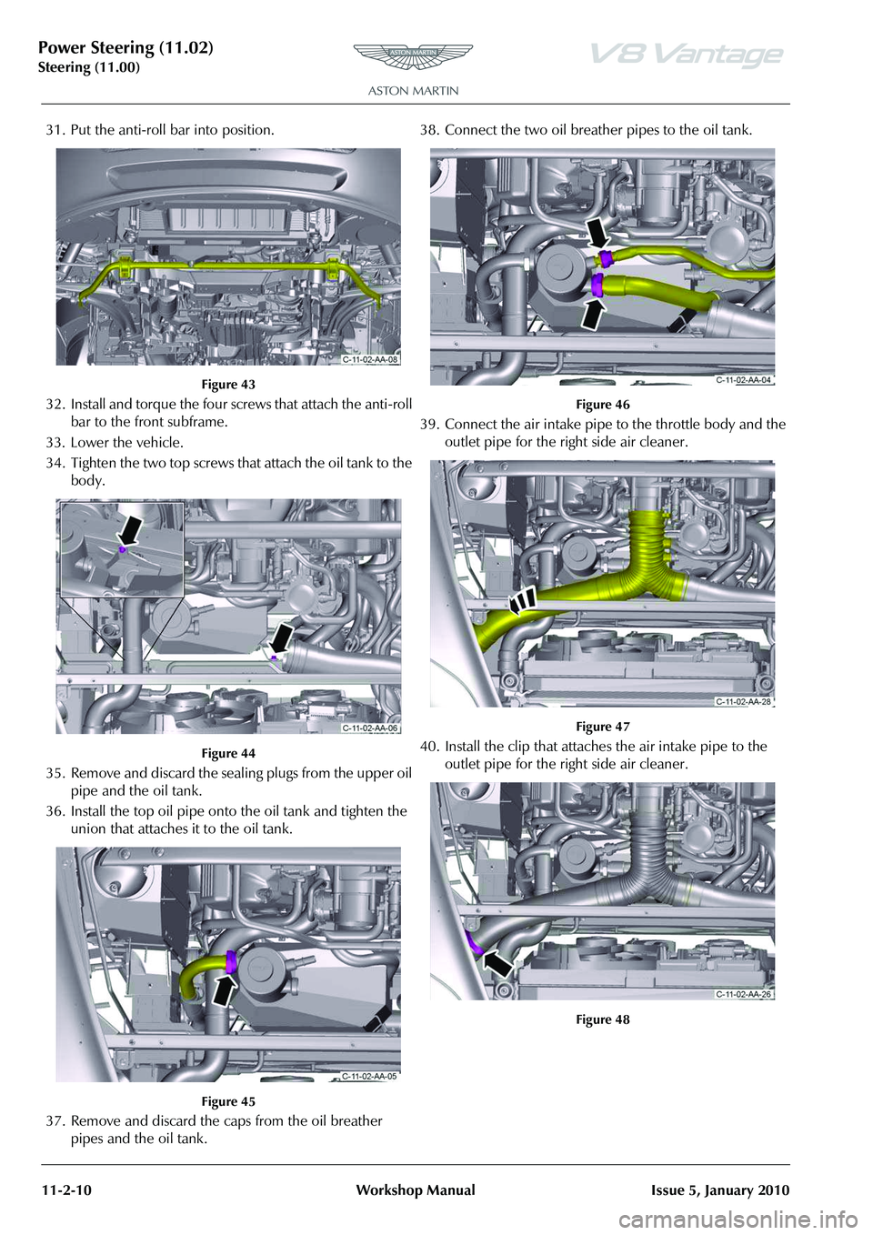
31. Put the anti-roll bar into position.
Figure 43
32. Install and torque the four screws that attach the anti-roll
bar to the front subframe.
33. Lower the vehicle.
34. Tighten the two top screws that attach the oil tank to the body.
Figure 44
35. Remove and discard the sealing plugs from the upper oil pipe and the oil tank.
36. Install the top oil pipe onto the oil tank and tighten the union that attaches it to the oil tank.
Figure 45
37. Remove and discard the caps from the oil breather pipes and the oil tank. 38. Connect the two oil breather pipes to the oil tank.
Figure 46
39. Connect the air intake pipe to the throttle body and the
outlet pipe for the right side air cleaner.
Figure 47
40. Install the clip that attaches the air intake pipe to the outlet pipe for the right side air cleaner.
Figure 48
Page 614 of 947
Power Steering (11.02)
Steering (11.00)
Issue 5, January 2010 Workshop Manual 11-2-11
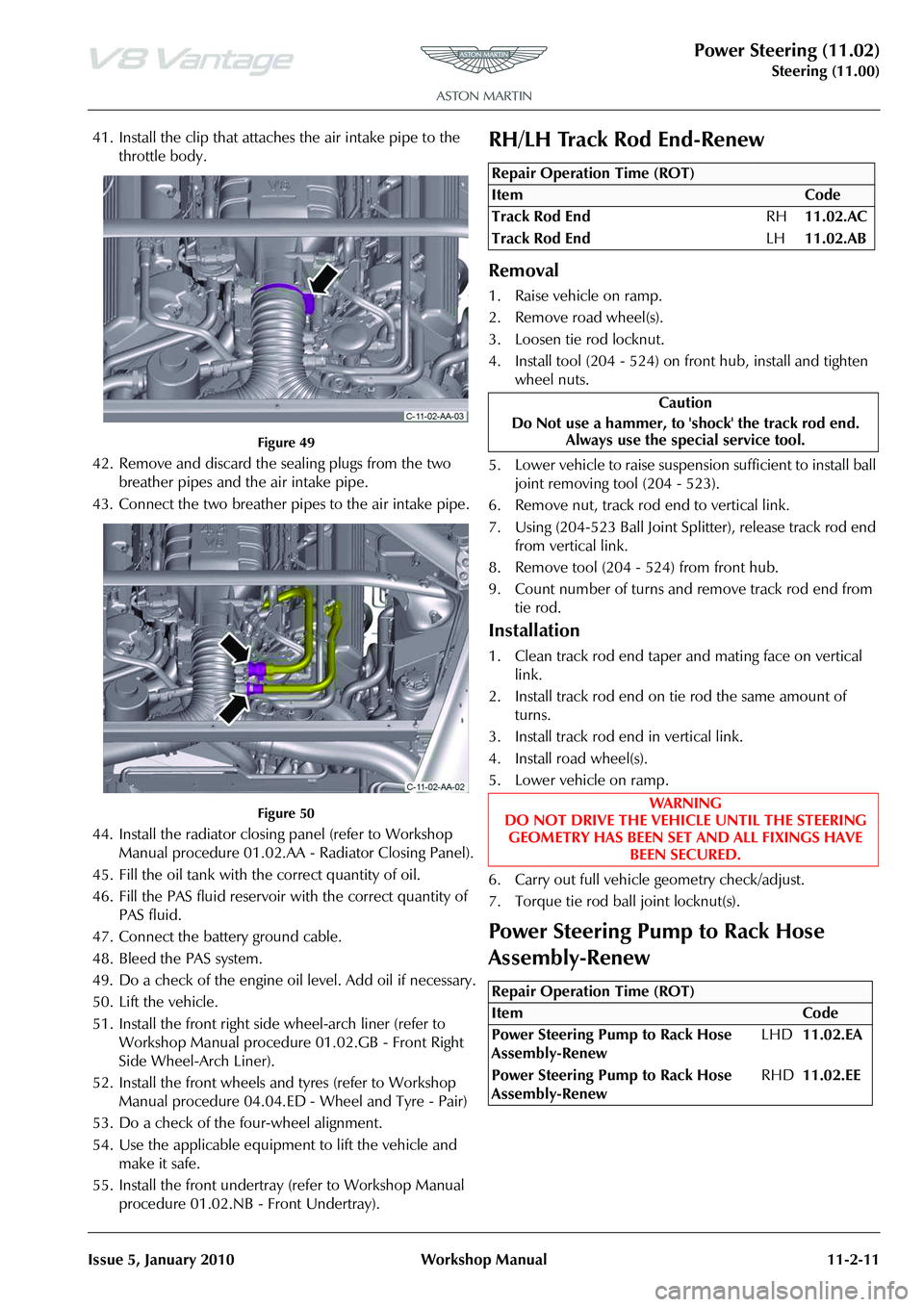
41. Install the clip that attaches the air intake pipe to the throttle body.
Figure 49
42. Remove and discard the sealing plugs from the two breather pipes and the air intake pipe.
43. Connect the two breather pipes to the air intake pipe.
Figure 50
44. Install the radiator closing panel (refer to Workshop Manual procedure 01.02.AA - Radiator Closing Panel).
45. Fill the oil tank with the correct quantity of oil.
46. Fill the PAS fluid reservoir with the correct quantity of
PAS fluid.
47. Connect the battery ground cable.
48. Bleed the PAS system.
49. Do a check of the engine oi l level. Add oil if necessary.
50. Lift the vehicle.
51. Install the front right side wheel-arch liner (refer to Workshop Manual procedure 01.02.GB - Front Right
Side Wheel-Arch Liner).
52. Install the front wheels and tyres (refer to Workshop Manual procedure 04.04.ED - Wheel and Tyre - Pair)
53. Do a check of the four-wheel alignment.
54. Use the applicable equipment to lift the vehicle and make it safe.
55. Install the front undertray (refer to Workshop Manual procedure 01.02.NB - Front Undertray).
RH/LH Track Rod End-Renew
Removal
1. Raise vehicle on ramp.
2. Remove road wheel(s).
3. Loosen tie rod locknut.
4. Install tool (204 - 524) on front hub, install and tighten
wheel nuts.
5. Lower vehicle to raise suspension sufficient to install ball joint removing tool (204 - 523).
6. Remove nut, track rod end to vertical link.
7. Using (204-523 Ball Joint Sp litter), release track rod end
from vertical link.
8. Remove tool (204 - 524) from front hub.
9. Count number of turns and remove track rod end from tie rod.
Installation
1. Clean track rod end taper and mating face on vertical link.
2. Install track rod end on tie rod the same amount of turns.
3. Install track rod end in vertical link.
4. Install road wheel(s).
5. Lower vehicle on ramp.
6. Carry out full vehicle geometry check/adjust.
7. Torque tie rod ball joint locknut(s).
Power Steering Pump to Rack Hose
Assembly-Renew
Repair Operation Time (ROT)
Repair Operation Time (ROT)
Page 615 of 947
Power Steering (11.02)
Steering (11.00)11-2-12 Workshop Manual Issue 5, January 2010
Removal
1. Remove PAS fluid from reservoir (syringe).
2. Remove throttle body duct for access. (clips x3).
3. Remove top bolts (x2) from engine oil tank and loosen
bottom bolts (x2) (allows ta nk to move to access pipe
support fixings).
4. Remove bolts (x2) securing pipe to body.
5. Disconnect sensor multiplug.
6. Remove hose from pump union.
7. Remove pipes from steering rack (bolt x1).
8. Remove pipe from vehicle.
Installation
1. Renew o-rings on PAS pipes and pump pipe.
2. Install hose to vehicle.
3. Install bolts brackets to body.
4. Install PAS pipes to rack (bolt x1).
5. Connect sensor multiplug.
6. Install pipe to pump union.
7. Install bolts and tighten oil tank fixings (torque).
8. Install throttle body duct. (clips x3).
9. Bleed PAS system (see Workshop Manual procedure 11.01.AA Power Assisted Steering System - Bleed).
Power Steering Rack to Cooler Hose-
Renew
Removal
1. Remove radiator grille (see Workshop Manual
procedure 01.08.AA Grille - Radiator - Renew).
2. Remove PAS fluid from reservoir (syringe). 3. Remove hose from cooler (clip x1) and support clips
(x2).
4. Remove undertray (see Workshop Manual procedure 01.02.NB Undertray - Front - Renew).
5. Remove bolt, bracket to lower radiator crossmember.
6. Lower ramp.
7. Remove throttle body duct for access. (clips x3).
8. Remove pipes from st eering rack (bolt x1).
9. Remove hose from vehicle (support clips x2).
Installation
1. Renew the O-rings on the PAS pipes.
2. Install hose to vehicle (support clips).
3. Install PAS pipes to rack (bolt x1).
4. Install throttle body duct. (clips x3).
5. Raise ramp.
6. Install support clip bolt to radiator crossmember.
7. Install hose to cooler and support clips (x2).
8. Install undertray (see Workshop Manual procedure 01.02.NB Undertray - Front - Renew).
9. Install radiator grille (see Workshop Manual procedure 01.08.AA Grille - Ra diator - Renew).
10. Top up PAS fluid.
WAR NI NG
AVOID EXCESSIVE SKIN CONTACT WITH MINERAL
OIL. MINERAL OILS REMOVE THE NATURAL FATS
FROM THE SKIN, LEADING TO DRYNESS, IRRITATION AND DERMATITIS.
Caution
Always plug pipes and hoses to prevent ingress of dirt or
moisture into the system.
Repair Operation Time (ROT)
Caution
Always plug pipes and hoses to prevent ingress of dirt or moisture into the system.
Page 616 of 947
Steering Column (11.04)
Steering (11.00)
Issue 4, November 2008 Workshop Manual 11-4-1
Steering (11.00)
Steering Column (11.04)
Description
The steering column has reach and tilt functions. These let
the driver manually set the position of the steering column.
by using the reach / tilt lever that is on the underside of the
steering column.This is indepe ndent of the ignition switch
position .
The steering intermediate shaft has two parts. The lower
shaft is attached to both th e steering gear and the upper
shaft.
The Electronic Steering Column Lock (ESCL) is attached to
the upper casting of the steering column and has a locking
pin. The steering column is electrically unlocked when the
ignition key is installed and operated to position 2. The lock
engages when the ignition switch is removed and the
steering wheel is turned to the centre position.
Specifications
Maintenance
Top Shroud for the Steering Column -
Remove and Install
Remove
1. Release the steering column adjustment lever.
2. Move the steering wheel to the longest column position.
3. Push the adjustment lever back to lock the steering
wheel.
4. Release the seven clips and remove the lower panel from the driver’s side of the instrument panel.
For Pre-08MY vehicles:
5. Put the key in the ignition switch and turn it to position 1 to release the Electronic Steering Column Lock (ESCL).
For 08MY vehicles or newer:
6. Put the Emotion Control Unit (ECU) into the docking station at position 2 to release the ESCL. 7. Turn the steering wheel to get access to the top screw in
the front face of the shroud at the left side .
8. Remove the screw.
9. Turn the steering wheel to get access to the top screw in the front face of the shroud at the right side .
10. Remove the screw.
11. Remove the top shroud.
Install
1. Put the top shroud in position on the steering column.
For Pre-08MY vehicles:
2. Put the key in the ignition switch and turn it to position1 to release the Electronic Steering Column Lock (ESCL).
For 08MY vehicles or newer:
3. Put the Emotion Control Unit (ECU) into the docking station at position 2 to release the ESCL.
4. Turn the steering wheel to get access to the top screw hole in the front face of the shroud at the left side.
5. Install the screw.
6. Turn the steering wheel to get access to the top screw hole in the front face of the shroud at the right side.
7. Install the screw.
Bottom Shroud for the Steering Column -
Remove and Install
Remove
1. Release the seven clips and remove the lower panel from the driver’s side of the instrument panel.
For Pre-08MY vehicles:
2. Put the key in the ignition switch and turn it to position 1 to release the Electronic Steering Column
Lock (ESCL).
For 08MY vehicles or newer:
3. Install the Emotion Control Unit (ECU) into the docking station at position 2 to release ESCL.
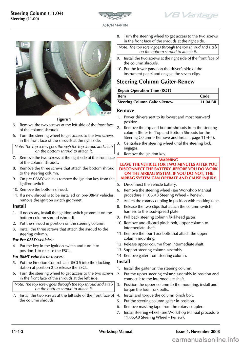
4. Turn the steering wheel to get access to the two screws in the front face of the shrouds at the left side (refer to
Figure 1).
Torque Figures
DescriptionNm.lb/ftNominal
Steering Column to cross
car beam 21-27 15.5-
19.924Nm
Upper column to I-shaft 27.3- 32.720-24.1 30Nm
Vee-yoke to pinion
extension shaft 15.5-
18.511.4-
21.217Nm
Power coupling to pinion 21.2- 28.815.6-
21.225Nm
Repair Operation Time (ROT)
Note: The top screw goes thro
ugh the top shroud and a tab
on the bottom shroud to attach it.
Note: The top screw goes thro ugh the top shroud and a tab
on the bottom shroud to attach it.
Repair Operation Time (ROT)
Page 617 of 947
Steering Column (11.04)
Steering (11.00)11-4-2 Workshop Manual Issue 4, November 2008
5. Remove the two screws at the left side of the front face of the column shrouds.
6. Turn the steering wheel to get access to the two screws in the front face of the shrouds at the right side.
7. Remove the two screws at the right side of the front face of the column shrouds.
8. Remove the three screws that attach the bottom shroud to the steering column.
9. On pre-08MY vehicles remove the ignition key from the igniiton switch.
10. Remove the bottom shroud.
11. If a new shroud is to be installed on pre-08MY vehicles, remove the ignition switch grommet.
Install
1. If necessary, install the ignition switch grommet on the bottom column shroud (shroud).
2. Put the shroud in position on the steering column.
3. Install the three screws that attach the shroud to the steering column.
For Pre-08MY vehicles:
4. Put the key in the ignition switch and turn it to position 1 to release the ESCL.
For 08MY vehicles or newer:
5. Put the Emotion Control Unit (ECU) into the docking station at position 2 to release the ESCL.
6. Turn the steering wheel to get access to the two screws in the front face of the shrouds at the left side.
7. Install the two screws at the left side of the front face of the column shrouds. 8. Turn the steering wheel to get access to the two screws
in the front face of the shrouds at the right side.
9. Install the two screws at the right side of the front face of the column shrouds.
10. Put the lower panel on the driver’s side of the instrument panel and engage the seven clips.
Steering Column Gaiter-Renew
Remove
1. Power driver's seat to its lowest and most rearward position.
2. Remove the top and bottom shrouds from the steering column (Refer to ’Top and Bottom Shrouds for the
Steering Column - Remove and Install’, page 11-4-4).
3. Centralise the steering whee l until the steering lock
engages.
4. Remove the ignition key.
5. Disconnect the vehicle battery.
6. Remove the steering wheel (see Workshop Manual procedure 11.06.AB Steering Wheel - Renew).
7. Attach the rotary coupling in position with masking tape.
8. Release the two clips that attach the column switch harness to the load-spread plate.
9. Pull back steering column bulkhead gaiter.
10. Remove and discard pinch bolt, upper column to intermediate shaft.
11. Remove the four Torx bolts that attach the upper column mounting.
12. Release upper column from intermediate shaft.
13. Support steering column assembly.
14. Remove gaiter from steering column.
Install
1. Install the gaiter on the steering column.
2. Put the upper steering column assembly in position and connect it to the intermediate shaft.
3. Position the upper column to the mounting, install and torque the four Torx bolts.
4. Install and torque the column pinch bolt.
5. Put the steering column gaiter in position.
6. Remove masking tape from the rotary coupler.
7. Install steering wheel (see Workshop Manual procedure 11.06.AB Steering Wheel - Renew).
Figure 1
Note: The top screw goes thro ugh the top shroud and a tab
on the bottom shroud to attach it.
Note: The top screw goes thro ugh the top shroud and a tab
on the bottom shroud to attach it.
Note: The top screw goes thro ugh the top shroud and a tab
on the bottom shroud to attach it.
Repair Operation Time (ROT)
ItemCode
Steering Column Gaiter-Renew 11.04.BB
WAR NI NG
LEAVE THE VEHICLE FOR TWO MINUTES AFTER YOU
DISCONNECT THE BATTERY ,BEFORE YOU DO WORK ON THE AIRBAG SYSTEM. IF YOU DO NOT, THE
AIRBAG SYSTEM CAN OPERATE AND CAUSE INJURY.
Page 618 of 947

Steering Column (11.04)
Steering (11.00)
Issue 4, November 2008 Workshop Manual 11-4-3
8. Connect vehicle battery.
9. Install the steering column shrouds (Refer to ’Top and Bottom Shrouds for the Steering Column - Remove and
Install’, page 11-4-4).
10. Put the driver’s seat and the steering column in their initial positions.
Upper Steering Column Assembly-
Renew
Remove
1. Power driver's seat to it s lowest and most rearward
position.
2. Remove the top and bottom shrouds from the steering column (Refer to ’Top and Bottom Shrouds for the
Steering Column - Remove and Install’, page 11-4-4).
3. Disconnect vehicle battery.
4. Centralise the steering whee l until the steering lock
engages.
5. Remove the ignition key.
6. Disconnect the battery.
7. Remove the steering wheel (Refer to ’Steering Wheel- Renew’, page 11-6-1).
8. Attach the rotary coupling in position with masking tape.
9. Disconnect steering column switch multiplugs (x5).
10. Remove screw securing load-spread plate to column and collect column shrouds mounting bracket.
11. Release clips (x2) from column switch harness to load- spread plate.
12. Pull back steering co lumn bulkhead gaiter. 13. Remove and discard pinch bolt from upper column to
intermediate shaft.Figure 1
14. Remove the four Torx screws from the upper column mounting.
15. Release upper column from intermediate shaft.
16. Disconnect multiplug from steering sensor and remove
steering column assembly.
17. Unclip steering column sw itches from column and
remove switch gear.
18. Mark fitted position of rotary coupler and remove rotary coupler.
19. Remove gaiter from steering column.
20. Remove Torx screws (x3) from securing steering sensor to mounting bracket.
21. Remove sensor.
22. Remove Torx screws (x3) that secure steering sensor mounting bracket to column and remove bracket.
Install
1. Position steering sensor mounting bracket, install and tighten Torx screws (x3).
2. Install the steering sensor, install and tighten Torx screws (x3).
3. Install gaiter on steering column.
4. Install steering column switch gear and secure clips.
5. Install the rotary coupler to marked position and secure
with masking tape.
6. Position upper steering column assembly and connect to intermediate shaft.
7. Connect multiplug to steering sensor.
8. Position upper column to mounting bracket, install and torque tighten Torx bolts (x4).
9. Install and torque tighten column pinch bolt.
10. Connect multiplugs (x5).
11. Position load-spread plate and secure harness clips (x2).
12. Install load-spread plate and secure with screw.
Repair Operation Time (ROT)