torque ASTON MARTIN V8 VANTAGE 2010 Workshop Manual
[x] Cancel search | Manufacturer: ASTON MARTIN, Model Year: 2010, Model line: V8 VANTAGE, Model: ASTON MARTIN V8 VANTAGE 2010Pages: 947, PDF Size: 43.21 MB
Page 759 of 947
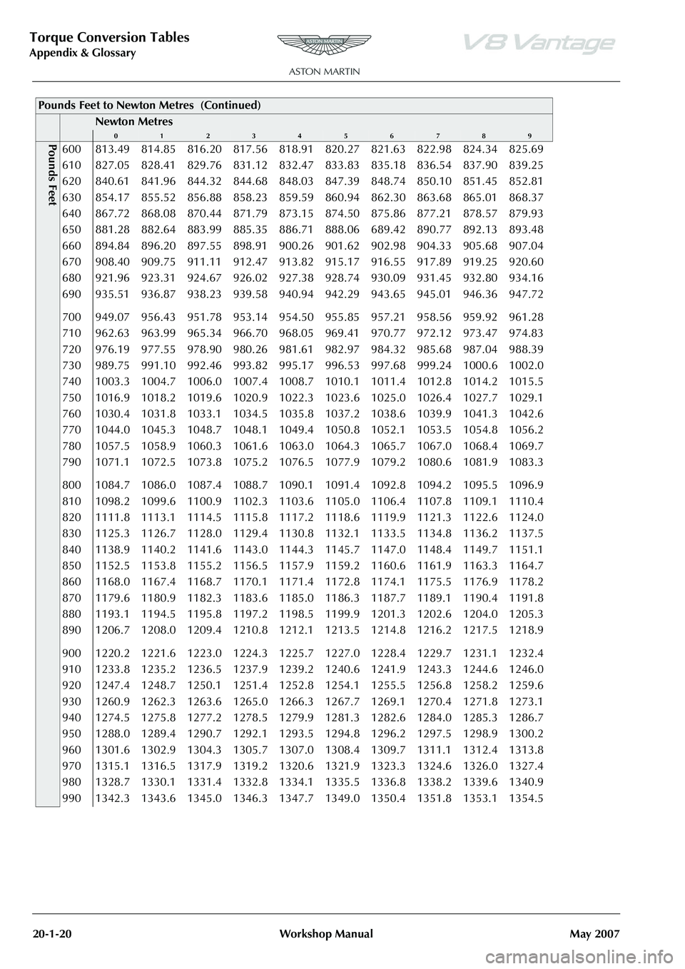
Torque Conversion Tables
Appendix & Glossary20-1-20 Workshop Manual May 2007
Pounds Feet600 813.49 814.85 816.20 817.56 818.91 820.27 821.63 822.98 824.34 825.69
610 827.05 828.41 829.76 831.12 832.47 833.83 835.18 836.54 837.90 839.25
620 840.61 841.96 844.32 844.68 848.03 847.39 848.74 850.10 851.45 852.81
630 854.17 855.52 856.88 858.23 859.59 860.94 862.30 863.68 865.01 868.37
640 867.72 868.08 870.44 871.79 873.15 874.50 875.86 877.21 878.57 879.93
650 881.28 882.64 883.99 885.35 886.71 888.06 689.42 890.77 892.13 893.48
660 894.84 896.20 897.55 898.91 900.26 901.62 902.98 904.33 905.68 907.04
670 908.40 909.75 911.11 912.47 913.82 915.17 916.55 917.89 919.25 920.60
680 921.96 923.31 924.67 926.02 927.38 928.74 930.09 931.45 932.80 934.16
690 935.51 936.87 938.23 939.58 940.94 942.29 943.65 945.01 946.36 947.72
700 949.07 956.43 951.78 953.14 954.50 955.85 957.21 958.56 959.92 961.28
710 962.63 963.99 965.34 966.70 968.05 969.41 970.77 972.12 973.47 974.83
720 976.19 977.55 978.90 980.26 981.61 982.97 984.32 985.68 987.04 988.39
730 989.75 991.10 992.46 993.82 995.17 996.53 997.68 999.24 1000.6 1002.0
740 1003.3 1004.7 1006.0 1007.4 1008.7 1010.1 1011.4 1012.8 1014.2 1015.5
750 1016.9 1018.2 1019.6 1020.9 1022.3 1023.6 1025.0 1026.4 1027.7 1029.1
760 1030.4 1031.8 1033.1 1034.5 1035.8 1037.2 1038.6 1039.9 1041.3 1042.6
770 1044.0 1045.3 1048.7 1048.1 1049.4 1050.8 1052.1 1053.5 1054.8 1056.2
780 1057.5 1058.9 1060.3 1061.6 1063.0 1064.3 1065.7 1067.0 1068.4 1069.7
790 1071.1 1072.5 1073.8 1075.2 1076.5 1077.9 1079.2 1080.6 1081.9 1083.3
800 1084.7 1086.0 1087.4 1088.7 1090.1 1091.4 1092.8 1094.2 1095.5 1096.9
810 1098.2 1099.6 1100.9 1102.3 1103.6 1105.0 1106.4 1107.8 1109.1 1110.4
820 1111.8 1113.1 1114.5 1115.8 1117.2 1118.6 1119.9 1121.3 1122.6 1124.0
830 1125.3 1126.7 1128.0 1129.4 1130.8 1132.1 1133.5 1134.8 1136.2 1137.5
840 1138.9 1140.2 1141.6 1143.0 1144.3 1145.7 1147.0 1148.4 1149.7 1151.1
850 1152.5 1153.8 1155.2 1156.5 1157.9 1159.2 1160.6 1161.9 1163.3 1164.7
860 1168.0 1167.4 1168.7 1170.1 1171.4 1172.8 1174.1 1175.5 1176.9 1178.2
870 1179.6 1180.9 1182.3 1183.6 1185.0 1186.3 1187.7 1189.1 1190.4 1191.8
880 1193.1 1194.5 1195.8 1197.2 1198.5 1199.9 1201.3 1202.6 1204.0 1205.3
890 1206.7 1208.0 1209.4 1210.8 1212.1 1213.5 1214.8 1216.2 1217.5 1218.9
900 1220.2 1221.6 1223.0 1224.3 1225.7 1227.0 1228.4 1229.7 1231.1 1232.4
910 1233.8 1235.2 1236.5 1237.9 1239.2 1240.6 1241.9 1243.3 1244.6 1246.0
920 1247.4 1248.7 1250.1 1251.4 1252.8 1254.1 1255.5 1256.8 1258.2 1259.6
930 1260.9 1262.3 1263.6 1265.0 1266.3 1267.7 1269.1 1270.4 1271.8 1273.1
940 1274.5 1275.8 1277.2 1278.5 1279.9 1281.3 1282.6 1284.0 1285.3 1286.7
950 1288.0 1289.4 1290.7 1292.1 1293.5 1294.8 1296.2 1297.5 1298.9 1300.2
960 1301.6 1302.9 1304.3 1305.7 1307.0 1308.4 1309.7 1311.1 1312.4 1313.8
970 1315.1 1316.5 1317.9 1319.2 1320.6 1321.9 1323.3 1324.6 1326.0 1327.4
980 1328.7 1330.1 1331.4 1332.8 1334.1 1335.5 1336.8 1338.2 1339.6 1340.9
990 1342.3 1343.6 1345.0 1346.3 1347.7 1349.0 1350.4 1351.8 1353.1 1354.5
Pounds Feet to Newton Metres (Continued)
Newton Metres
0123456789
Page 792 of 947
Squeaks and Rattles Repair Manual
Page 8 of 21 Issue 3
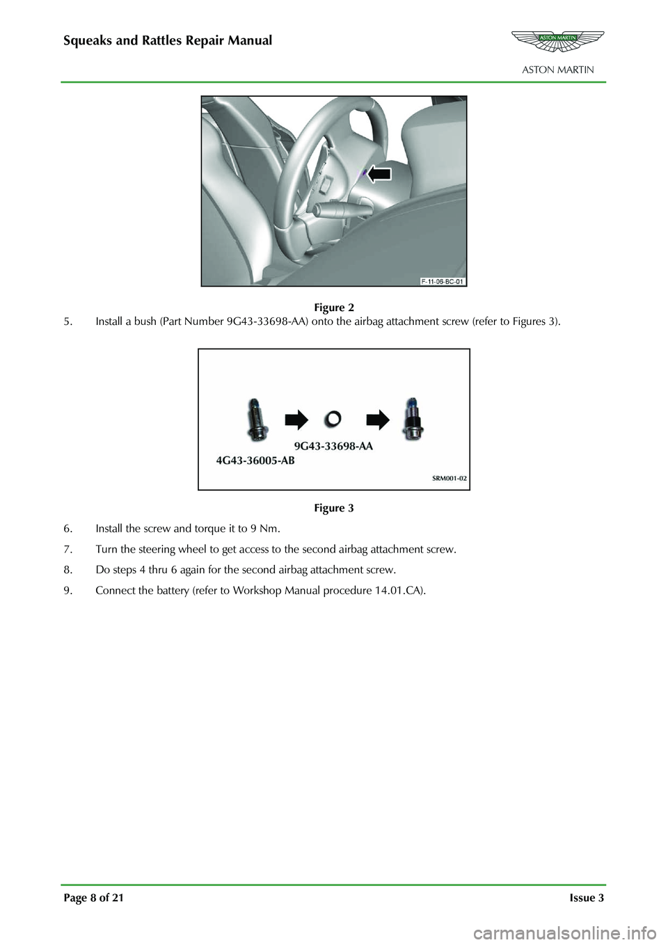
Figure 2
5. Install a bush (Part Number 9G43-33698-AA) onto th e airbag attachment screw (refer to Figures 3).
Figure 3
6. Install the screw and torque it to 9 Nm.
7. Turn the steering wheel to get access to the second airbag attachment screw.
8. Do steps 4 thru 6 again for the second airbag attachment screw.
9. Connect the battery (refer to Work shop Manual procedure 14.01.CA).
Page 794 of 947
Squeaks and Rattles Repair Manual
Page 10 of 21 Issue 3
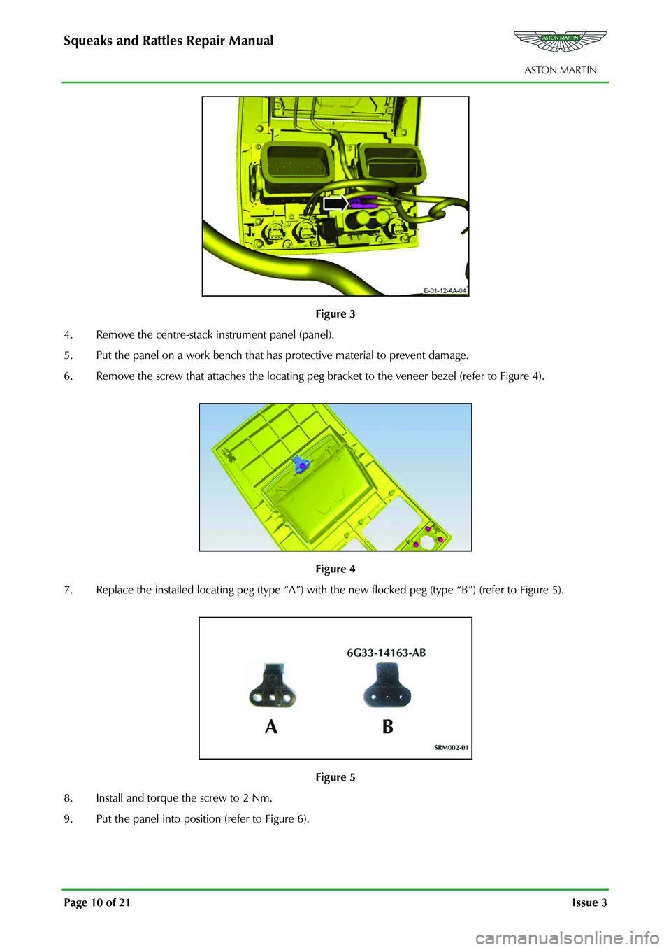
Figure 3
4. Remove the centre-stack instrument panel (panel).
5. Put the panel on a work bench that has protective material to prevent damage.
6. Remove the screw that attaches the locating peg br acket to the veneer bezel (refer to Figure 4).
Figure 4
7. Replace the installed locating peg (type “A”) with th e new flocked peg (type “B”) (refer to Figure 5).
Figure 5
8. Install and torque the screw to 2 Nm.
9. Put the panel into position (refer to Figure 6).
Page 803 of 947
Squeaks and Rattles Repair Manual
July 2010 Page 19 of 21
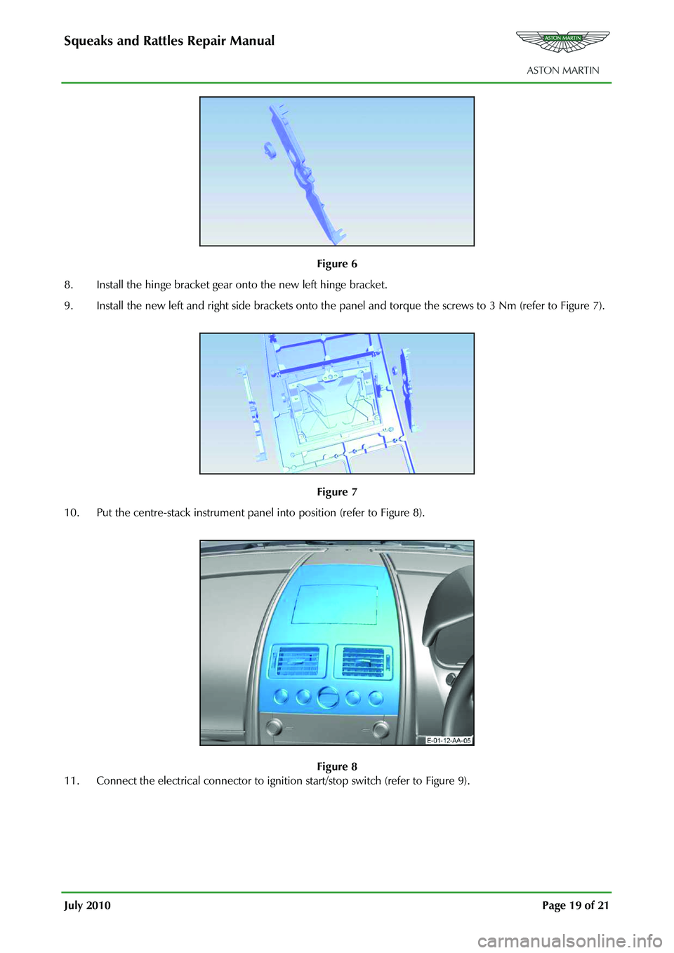
Figure 6
8. Install the hinge bracket gear onto the new left hinge bracket.
9. Install the new left and right side brackets onto the pane l and torque the screws to 3 Nm (refer to Figure 7).
Figure 7
10. Put the centre-stack instrument panel into position (refer to Figure 8).
Figure 8
11. Connect the electrical connector to ignition start/stop switch (refer to Figure 9).
Page 853 of 947
AML EOBD System Operation Summary
Rory O’Curry Aston Martin Lagonda CONFIDENTIAL 1 May 2009
Misfire Monitor (continued)
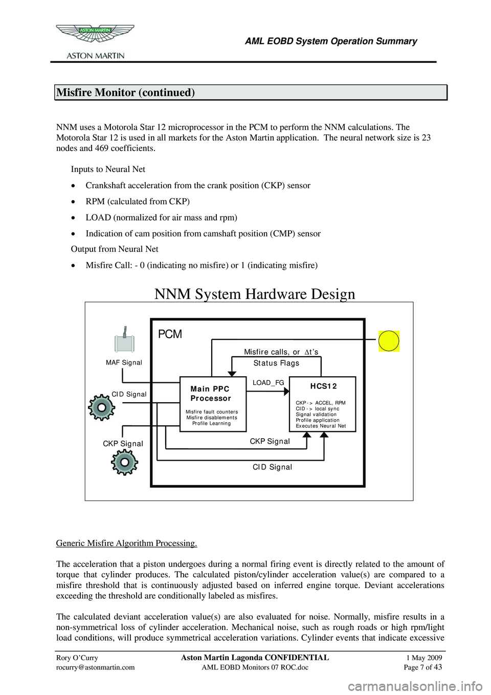
NNM uses a Motorola Star 12 microprocessor in the PCM to perform the NNM calculations. The
Motorola Star 12 is used in all markets for the Ast on Martin application. The neural network size is 23
nodes and 469 coefficients.
Inputs to Neural Net
• Crankshaft acceleration from the crank position (CKP) sensor
• RPM (calculated from CKP)
• LOAD (normalized for air mass and rpm)
• Indication of cam position from camshaft position (CMP) sensor
Output from Neural Net
• Misfire Call: - 0 (indicating no misfire) or 1 (indicating misfire)
[email protected] AML EOBD Monitors 07 ROC.doc Page 7 of 43
NNM System Hardware Design
PCM MIL
Generic Misfire Algorithm Processing.
The acceleration that a piston undergoes during a normal firing event is directly related to the amount of
torque that cylinder produces. The calculated piston/cylinder acceleration value(s) are compared to a
misfire threshold that is continuously adjusted based on inferred engine torque. Deviant accelerations
exceeding the threshold are conditionally labeled as misfires.
The calculated deviant acceleration value(s) are also evaluated for noise. Normally, misfire results in a
non-symmetrical loss of cylinder acceleration. Mechan ical noise, such as rough roads or high rpm/light
load conditions, will produce symmetrical acceleration va riations. Cylinder events that indicate excessive
MAF Signal
CKP Signal
Main PPC
Processor
HCS12HCS12LOAD_FG
CKP Signal
Misfire calls, or
Δt’s
Misfire fault counters
Status Flags
CID Signal
Misfire disablements
Profile Learning CKP
-> ACCEL, RPM
CID -> local sync
Signal validation
Profile application
Executes Neural Net
CID Signal
Page 854 of 947
AML EOBD System Operation Summary
Rory O’Curry Aston Martin Lagonda CONFIDENTIAL 1 May 2009
[email protected] AML EOBD Monitors 07 ROC.doc Page 8 of 43
deviant accelerations of this type are considered noise. Noise-free deviant acceleration exceeding a given
threshold is labeled a misfire.
The number of misfires are counted over a continuous 200 revolution and 1000 (or 4000)
revolution period. (The revolution counters are not reset if the misfire monitor is temporarily disabled such
as for negative torque mode, etc.) At the end of the evaluation period, the total misfire rate and the misfire
rate for each individual cylinder is computed. The misfire rate evaluated every 200 revolution period
(Type A) and compared to a threshold value obtaine d from an engine speed/load table. This misfire
threshold is designed to prevent damage to the cat alyst due to sustained excessive temperature. If the
misfire threshold is exceeded and the catalyst temperature model calculates a catalyst mid-bed temperature
that exceeds the catalyst damage threshold, the MIL blinks at a 1 Hz rate while the misfire is present. If the
threshold is again exceeded on a subsequent driving cy cle, the MIL is illuminated. If a single cylinder is
indicated to be consistently misfiring in excess of the catalyst damage criteria, the fuel injector to that
cylinder may be shut off for a period of time to pr event catalyst damage. Up to two cylinders may be
disabled at the same time. This fuel shut-off feature is used on many 8-cylinder engines. It is never used
on a 4-cylinder or 6-cylinder engine. Next, the misf ire rate is evaluated every 1000 (or 4000) rev period
and compared to a single ( Type B ) threshold value to indicate an emission-threshold malfunction. If a
1000 rev period is calibrated, a single 1000 rev exceedence from startup or four subsequent 1000 rev
exceedences on a drive cycle after start-up is used as the malfunction criteria. If a 4000 rev period is
calibrated, a single 4000 rev exceedence is used to indicate an emission-threshold malfunction.
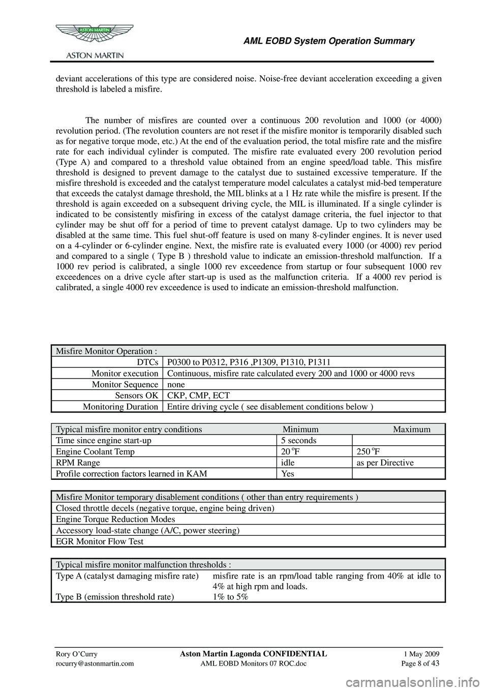
Misfire Monitor Operation :
DTCs P0300 to P0312, P316 ,P1309, P1310, P1311
Monitor execution Continuous, misfire rate calculated every 200 and 1000 or 4000 revs
Monitor Sequence none
Sensors OK CKP, CMP, ECT
Monitoring Duration Entire driving cycle ( see disablement conditions below )
Typical misfire monitor entry conditions Minimum Maximum
Time since engine start-up 5 seconds
Engine Coolant Temp 20 oF 250 oF
RPM Range idle as per Directive
Profile correction factors learned in KAM Yes
Misfire Monitor temporary disablement conditions ( other than entry requirements )
Closed throttle decels (negative torque, engine being driven)
Engine Torque Reduction Modes
Accessory load-state change (A/C, power steering)
EGR Monitor Flow Test
Typical misfire monitor malfunction thresholds :
Type A (catalyst damaging misfire rate) misfire rate is an rpm/load table ranging from 40% at idle to
4% at high rpm and loads.
Type B (emission threshold rate) 1% to 5%
Page 862 of 947
AML EOBD System Operation Summary
Rory O’Curry Aston Martin Lagonda CONFIDENTIAL 1 May 2009
[email protected] AML EOBD Monitors 07 ROC.doc Page 16 of 43
Electronic Throttle Monitor
Where ETC is used, the system monitor incorporates a complex safety strategy. The main ETC feature is
based around a driver demand torque that is deliver ed as an output shaft torque through the correct
positioning of the throttle plate. The Independent Plausibility Check (IPC) feature performs the primary
monitoring function. This resides within the main microprocessor and is responsible for determining the
driver demand torque and comparing it to an estimate of the actual brake torque delivered. If the generated
torque exceeds the driver demanded torque by a speci fied amount, then the appropriate FMEM action is
taken.
With the IPC feature being on the main processor, an intelligent VQZ watchdog is incorporated on a
separate processor to monitor the performance of the IPC and the main processor. If the VQZ determines
that the IPC function is impaired in any way then it takes the appropriate FMEM action.
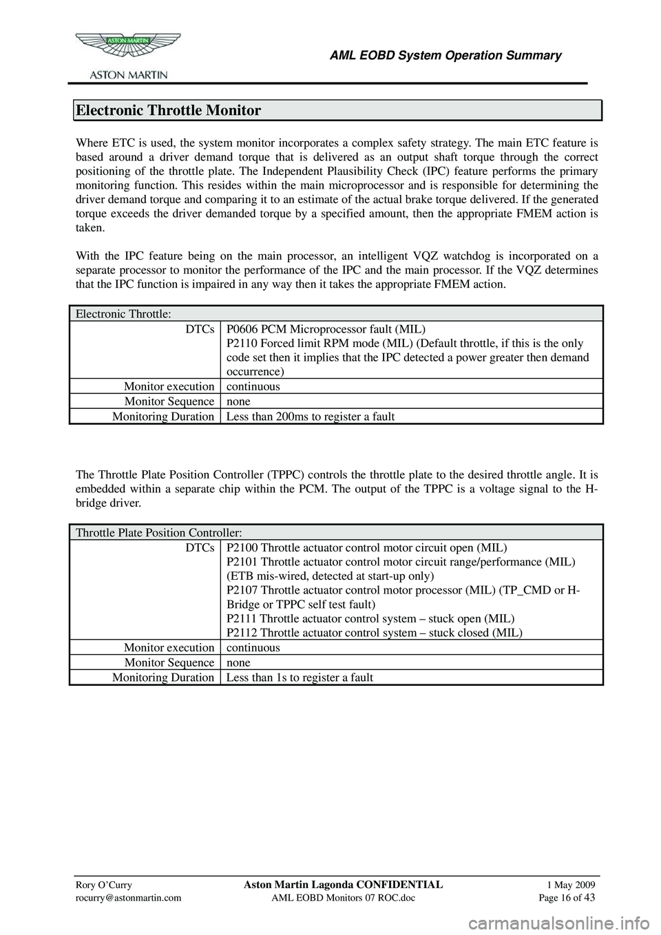
Electronic Throttle:
DTCs P0606 PCM Microprocessor fault (MIL)
P2110 Forced limit RPM mode (MIL) (Default throttle, if this is the only
code set then it implies that the IPC detected a power greater then demand
occurrence)
Monitor execution continuous
Monitor Sequence none
Monitoring Duration Less than 200ms to register a fault
The Throttle Plate Position Controller (TPPC) controls the throttle plate to the desired throttle angle. It is
embedded within a separate chip within the PCM. The output of the TPPC is a voltage signal to the H-
bridge driver.
Throttle Plate Position Controller:
DTCs P2100 Throttle actuator control motor circuit open (MIL)
P2101 Throttle actuator control motor circuit range/performance (MIL)
(ETB mis-wired, detected at start-up only)
P2107 Throttle actuator control motor processor (MIL) (TP_CMD or H-
Bridge or TPPC self test fault)
P2111 Throttle actuator control system – stuck open (MIL)
P2112 Throttle actuator control system – stuck closed (MIL)
Monitor execution continuous
Monitor Sequence none
Monitoring Duration Less than 1s to register a fault
Page 876 of 947
AML EOBD System Operation Summary
Rory O’Curry Aston Martin Lagonda CONFIDENTIAL 1 May 2009
[email protected] AML EOBD Monitors 07 ROC.doc Page 30 of 43
Comprehensive Component Monitor - Manual Transmission.
General.
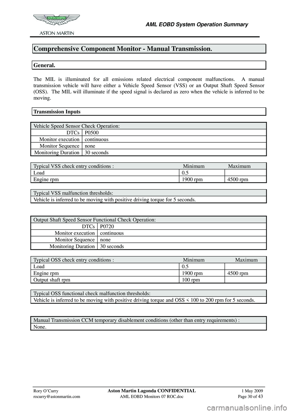
The MIL is illuminated for all emissions relate d electrical component malfunctions. A manual
transmission vehicle will have either a Vehicle Speed Sensor (VSS) or an Output Shaft Speed Sensor
(OSS). The MIL will illuminate if the speed signal is declared as zero when the vehicle is inferred to be
moving.
Transmission Inputs
Vehicle Speed Sensor Check Operation:
DTCs P0500
Monitor execution continuous
Monitor Sequence none
Monitoring Duration 30 seconds
Typical VSS check entry conditions : Minimum Maximum
Load 0.5
Engine rpm 1900 rpm 4500 rpm
Typical VSS malfunction thresholds:
Vehicle is inferred to be moving with positive driving torque for 5 seconds.
Output Shaft Speed Sensor Functional Check Operation:
DTCs P0720
Monitor execution continuous
Monitor Sequence none
Monitoring Duration 30 seconds
Typical OSS check entry conditions : Minimum Maximum
Load 0.5
Engine rpm 1900 rpm 4500 rpm
Output shaft rpm 100 rpm
Typical OSS functional check malfunction thresholds:
Vehicle is inferred to be moving with positive driving torque and OSS < 100 to 200 rpm for 5 seconds.
Manual Transmission CCM temporary disablement conditions (other than entry requirements) :
None.
Page 877 of 947
AML EOBD System Operation Summary
Rory O’Curry Aston Martin Lagonda CONFIDENTIAL 1 May 2009
[email protected] AML EOBD Monitors 07 ROC.doc Page 31 of 43
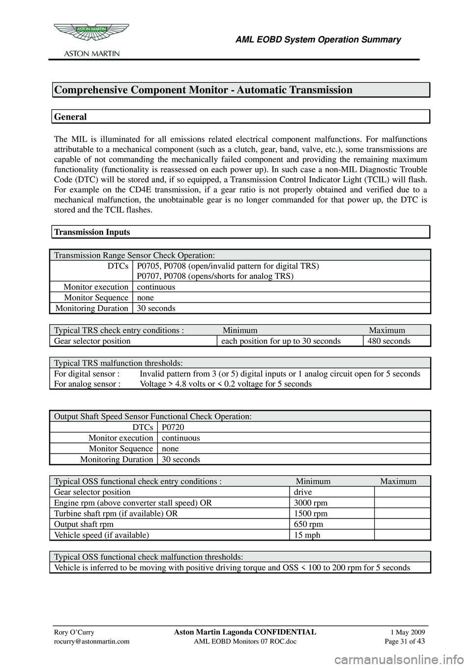
Comprehensive Component Monitor - Automatic Transmission
General
The MIL is illuminated for all emissions related electrical component malfunctions. For malfunctions
attributable to a mechanical component (such as a clutch, gear, band, valve, etc.), some transmissions are
capable of not commanding the mechanically faile d component and providing the remaining maximum
functionality (functionality is reassessed on each power up). In such case a non-MIL Diagnostic Trouble
Code (DTC) will be stored and, if so equipped, a Transmission Control Indicator Light (TCIL) will flash.
For example on the CD4E transmission, if a gear ratio is not properly obtained and verified due to a
mechanical malfunction, the unobtainable gear is no longer commanded for that power up, the DTC is
stored and the TCIL flashes.
Transmission Inputs
Transmission Range Sensor Check Operation:
DTCs P0705, P0708 (open/invalid pattern for digital TRS)
P0707, P0708 (opens/shorts for analog TRS)
Monitor execution continuous
Monitor Sequence none
Monitoring Duration 30 seconds
Typical TRS check entry conditions : Minimum Maximum
Gear selector position each position for up to 30 seconds 480 seconds
Typical TRS malfunction thresholds:
For digital sensor : Invalid pattern from 3 (or 5) digital inputs or 1 analog circuit open for 5 seconds
For analog sensor : Voltage > 4.8 volts or < 0.2 voltage for 5 seconds
Output Shaft Speed Sensor Functional Check Operation:
DTCs P0720
Monitor execution continuous
Monitor Sequence none
Monitoring Duration 30 seconds
Typical OSS functional check entry conditions : Minimum Maximum
Gear selector position drive
Engine rpm (above converter stall speed) OR 3000 rpm
Turbine shaft rpm (if available) OR 1500 rpm
Output shaft rpm 650 rpm
Vehicle speed (if available) 15 mph
Typical OSS functional check malfunction thresholds:
Vehicle is inferred to be moving with positive driving torque and OSS < 100 to 200 rpm for 5 seconds
Page 878 of 947
AML EOBD System Operation Summary
Rory O’Curry Aston Martin Lagonda CONFIDENTIAL 1 May 2009
[email protected] AML EOBD Monitors 07 ROC.doc Page 32 of 43
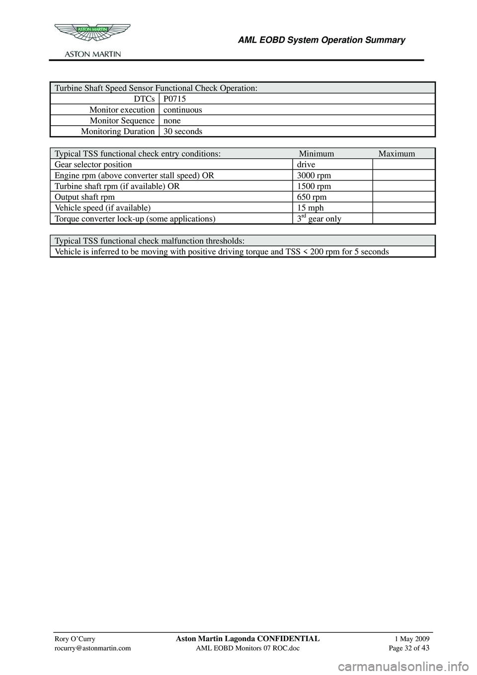
Turbine Shaft Speed Sensor Functional Check Operation:
DTCs P0715
Monitor execution continuous
Monitor Sequence none
Monitoring Duration 30 seconds
Typical TSS functional check entry conditions: Minimum Maximum
Gear selector position drive
Engine rpm (above converter stall speed) OR 3000 rpm
Turbine shaft rpm (if available) OR 1500 rpm
Output shaft rpm 650 rpm
Vehicle speed (if available) 15 mph
Torque converter lock-up (some applications) 3rd gear only
Typical TSS functional check malfunction thresholds:
Vehicle is inferred to be moving with positiv e driving torque and TSS < 200 rpm for 5 seconds