ignition AUDI A5 COUPE 2010 Repair Manual
[x] Cancel search | Manufacturer: AUDI, Model Year: 2010, Model line: A5 COUPE, Model: AUDI A5 COUPE 2010Pages: 360, PDF Size: 84.39 MB
Page 126 of 360
• ..__A_ d_ a-'- p_t _iv _ e_ c_r _u _ i_s _e _ c_o_ n_t _r _o _l _____________________________________________ _
Driving pro
gram
Di sta nce 1
Distance 2
D ist an ce 3
& WARNING
dynamic
1
2
2
3
standard
2
3
3
4
comfort
3
4
4
5
-
When setting the distance , the driver is responsible for adhering
to the respective national and country -specific regulations.
• Following other vehicles too closely increases the risk of colli
sions and serious personal injury .
• Setting short distances to the traffic ahead reduces the time
and distance available to bring your vehicle to a safe stop and
makes it even more necessary to pay close attention to traffic .
• Always use good judgment and select a safe following distance
for the traffic , road and weather conditions.
[ i J Tips
T he di stance se tting is re set to the factory defa ult DISTANCE 3 the
next time the ignition is turned on. •
Driver information
Applies to vehic les: with adapt ive cruise contro l
Displays in the instrument cluster
Dependin g o n the driving si tuati on, driver inform ation is
dis pla yed in the i nstr umen t clus ter.
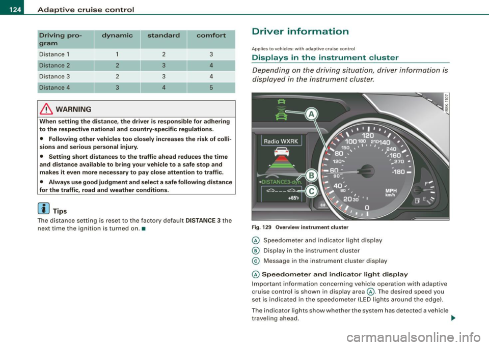
F ig . 129 Overview instrument clu ste r
© Speedome ter and indicator lig ht dis play
® Displ ay in the instru ment clus ter
© M essage in the instr ument clus ter disp lay
© Speedometer and indicator light display
Im port ant inf orm ati on c once rning v ehicle opera tion with a daptiv e
cruise control is shown in display area@. T he desired speed you
s et is in dica ted in the sp eedometer ( LED l igh ts a rou nd th e e dge).
T he indicator lig hts show whether the system has detected a v ehic le
t rave ling ahead . ..,
Page 148 of 360
• ..__A_ u_ d_ i _d _ r_ i_v _e_ s_ e_ le_c_ t _________________________________________________ _
& WARNING
Pay attention to t raffi c when operating Audi dri ve se lect to prevent
potenti al risk of an accid ent.
[ i J Tips
If you remove the igniti on key, AUTO mode is se t the next time you
start the ignition .•
App lies to vehicles: w ith MM I and dr ive select
Setting the INDIVIDUAL mode
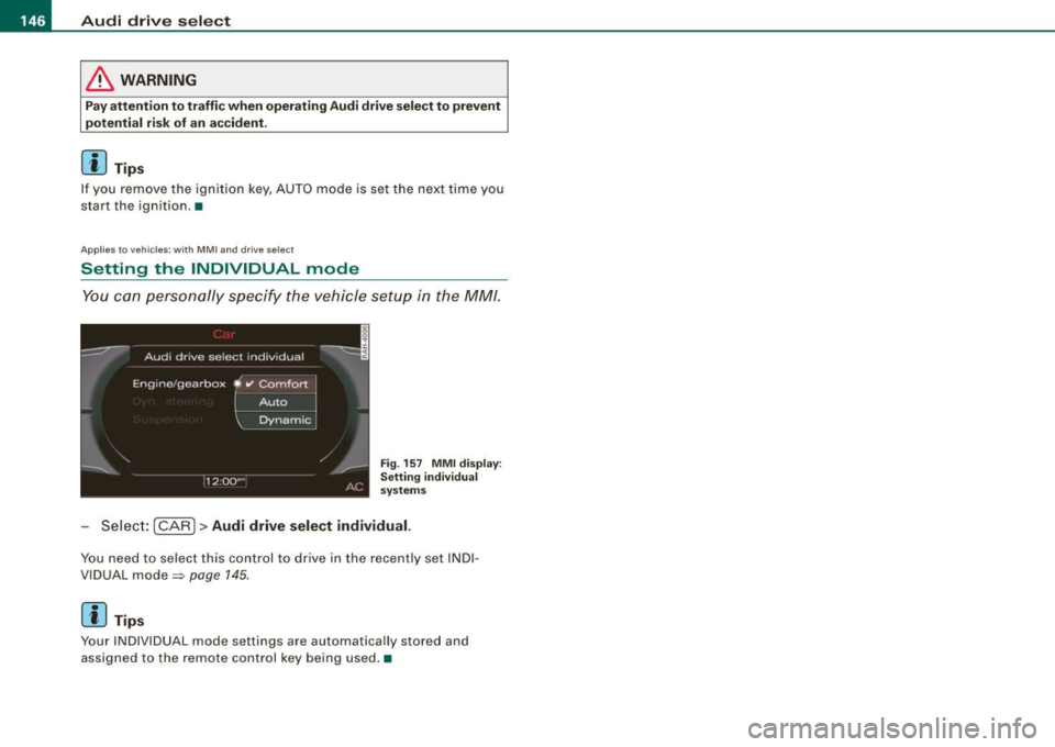
Y ou can pe rsonally specify the vehicle setup in the M M/.
Fi g. 15 7 MMI di spl ay:
S etting individu al
sy stem s
Sele ct: [CAR]> Audi drive select individual.
Yo u n eed to se le ct this con trol to dr ive in the recently set I NDI
V IDUAL mode=:>
page 145.
[ i J Tips
Your INDIVI DUAL mode settings are automatically stored and
assigned to the remote con trol key being used .•
Page 149 of 360

____________________________________________________ T_ r_ a _n _s_ m_ i_ s _ s_ i_ o _ n _ ___._
Transmission
Manual transmission
Applies to vehicles: with manual transmission
Gearshift lever
The clutch pedal must be depressed all the way before
you can start the engine.
The manual transmission in your Audi is equipped with an
interlock-feature.
- Depress the clutch pedal all the way.
- Start the engine with the gearshift
lever in Neutral and
the clutch pedal depressed .
0 Note
Always depress the clutch pedal fully when changing gears. Do not
hold the vehicle on a hill with the clutch pedal partially depressed .
This may cause premature clutch wear or damage .
[ i J Tips
• Resting your hand on the gearshift lever knob while driving will
cause premature wear in the transmission.
• The back-up lights go on when you shift into Reverse with the
ignition on .•
Con tro ls and eq uip
ment
App lies to vehicles: with manual transm ission
Gearshift pattern (6-speed manual
transmission )
Engaging reverse gear (R)
Fig. 158 Gearshift
pattern: 6-s peed
manual transmission
- Move the shift lever all the way to the left, press it down,
then push it forward.
Especially after driving forward, stop the vehicle completely, shift
into
Neutral and rest the shift lever briefly in Neutral before shifting
into
Reverse. •
Automatic transmission
Applies to vehicles: wi th au tomat ic transmission
Introduction
Your vehicle is equipped with an electronically controlled 6 -speed
automatic transmission. Upshifting and downshifting takes place
automatically. ~
Vehicle care I I irechnical data
Page 152 of 360
• ..__T_ r_a _n_ s_ m_ is_ s_i o _ n ______________________________________________________ _
Before you move the selector lever to R, press both the button in the
handle of the selector lever
and the brake pedal at the same time .
When the ignition is on , the backup lights illumina te when the
selector lever is moved into R.
N -N eutr al
The transmission is in neutral in this position. Shift to this position
for standing with the brakes applied=:>
page 150.
When the vehicle is stationary or at speeds below 3 mph (5 km/h) ,
you must always apply the footbrake before and while moving the lever out of
N .
D -N or mal pos itio n fo r d rivi ng forward
Posi tion Dis for normal city and highway driving . It ranges from zero
to top speed and all gears shift automatically, depending on engine load , driv ing spe ed and automa tically selected shift programs .
When the vehicle is s tationary or at speeds below 3 mph (5 km/h).
you must always apply the foot brake befo re and while moving the
lever to
D ou t of N.
In certain circumstances it may be advantageous to temporarily
switch to the manual shift program to manually select gear ratios to
match specific driving conditions=:>
page 152.
S -Sp o rt posit io n*
Select this pos ition for sportier performance. In this position, the
transmission will not upshift as soon , allowing the vehicle to use the
increased power available at higher engine speeds to achieve live
lier acceleration.
When the vehicle is stationary or at speeds below 3 mph (5 km/h) ,
you must always apply the foot brake befo re and while moving the
lever to
S out of N.
& WARNING
R ea d and foll ow all WARNIN GS =:> & in "Dri vin g th e a utom atic
tr an smi ssion " on
pag e 148.
0 Note
Coasting downhill with the transmission in N and the engine not
running will result in damage to the automa tic transmission and
possibly the catalytic converter. •
Applies t o ve hicl es: wit h automa tic trans mis si on
Automatic Shift Lock (ASL )
The Automatic Shift Lock safeguards you against acciden
tally shifting into a forward or the reverse gear and
causing the vehicle to move unintentionally.
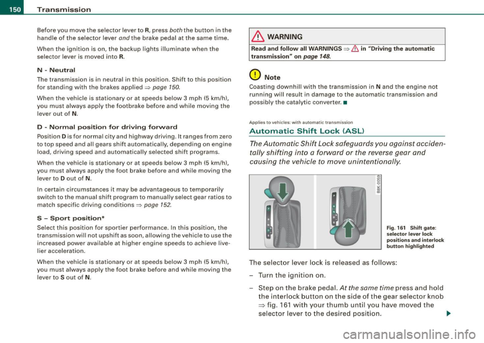
F ig . 16 1 Shift gate:
se lector le ver loc k
posit ions a nd int erl ock
butt on hi gh ligh ted
The selector lever l ock is released as follows :
Turn the ignit ion on .
Step on the brake peda l.
At the same time press and hold
the interlock button on the s ide of the gear selector knob
=> fig. 161 w ith your thumb until you have moved the
selector lever to t he desired position.
~
Page 153 of 360
Tra ns mi ssio n -
----------------
Aut omat ic selec to r l ever lock
The se lector lever is locked in the P and N positions when the igni
tion is turned on. To move the lever from these positions the driver
must depress the brake pedal. As a reminder to the driver, the
follow ing warning appears in the instrument cluster display when
the selector is in
P and N:
W hen sta tio nary app ly footbrake while selecting g ear
A time delay e lement prevents the selector lever from locking when
it is moved through the
N position (going from R to Dl. The locking
e lement will lock the selector lever if the lever is left in N (Neutral)
for more than approximately 1 second, without the brake peda l
being pressed.
At speeds above about 3 mph (5 km/h) the Automatic Shift Lock is
automatically deactivated in the
N position .
Interlock butt on
The lock button on the selector lever prevents the lever from being
accidentally shifted into certain positions. Pressing this button
deactivates the selector lever lock. Depending on the direction of
the shift, the selector lever locks at different positions. The positions
are highlighted in the illustration =>
page 150, fig. 161.
Igniti on key sa fe ty in te rlo ck
The key cannot be removed from the ignition unless the selector
lever is in the
P park position. When the ignition key is removed, the
selector lever wil l be locked in the
P position. •
Applies to vehicles : with automatic transm iss ion
Kick-down
The kick-down feature allows the vehicle to generate
maximum acceleration .
When you press the acce lerator pedal beyond the resistance point
that is reached at ful l throttle, the transmission wi ll select a lower
gear ratio based on vehic le speed and engine RPM. The engine RPM
Controls and equip
ment
wi ll be controlled to produce maximum vehic le acceleration as long
as you continue to press the accelerator pedal beyond this resis
tance point .
& WARNING
Be care ful whe n usi ng the kick -dow n fe atur e on slipp ery ro ads .
R apid acc eleration may cau se th e v ehicle to skid . •
App lies to vehicles : with automat ic transm ission
Dynamic shift program (DSP)
The aut omatic transmission is electronically controlled.
The transmission is se lf adapting and will a ut oma tica lly se lect the
best shift program suited to the driving conditions and driving style.
The transmission will select one of the
eco nom y programs when
you drive at a steady speed or a g radually changing speed without
heavy acceleration. This achieves optimum fuel efficiency, with early
upshifting and delayed downshifting.
The transmission will automatically select the
s p ort y shift programs
when you drive at higher speeds, or with heavy acceleration and
frequent ly changing speeds . Upshifts are delayed to make full use
of engine power . Downshifting takes place at higher engine speeds
than in the economy programs .
The se lect ion of the most su itable shift program is a continuous,
automatic process. The driver can also make the transmission
sw itch to a sporty program by
quick ly pressing down the gas peda l.
This causes the transmission to shift down to a lower gear to
achieve rapid acceleration, e.g. for quickly passing another vehicle .
You do not need to press the gas pedal into the kick-down range.
After the transm ission has upshifted, the original program is
selected accord ing to your driving sty le.
An additiona l shift program allows the automatic transmission to
select the proper gear for uph ill and downhi ll gradients. ..,.
I • •
Page 156 of 360
• ..__T_ ra_ n_s_ m_ i_ s _s_ i_ o _n ___________________________________________________ _
0 Note
If the transmission switches to fail-safe mode, you should take the
vehicle to an authorized Audi dealership as soon as possible to have
the condition corrected .•
A pplies to veh icles : with aut om at ic transmi ssio n
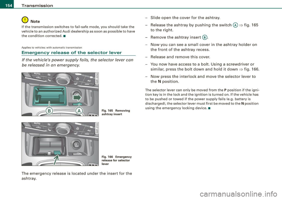
Emergency release of the selector lever
If the vehicle's power supply fails, the selector lever can
be released in an emergency.
Fig. 165 Removing
ashtray insert
Fig. 166 Emergency
release for selector
lever
The emergency release is located under the insert for the
ashtray . -
Slide open the cover for the ashtray.
- Release the ashtray by pushing the switch@~ fig. 165
to the right.
- Remove the ashtray insert @.
- Now you can see a small cover in the ashtray holder on
the front of the ashtray recess.
- Release and remove this cover.
- You now have access to a bolt . Using a screwdriver or
similar, press the bolt down and hold it down ~ fig. 166.
Now press the interlock and move the selector lever to
the
N position.
Th e selector le ve r can only be moved from th e P position if the igni
tion key is in the lock and the ignition is turned on. If the vehicle has
to be pushed or towed if the power supply fails (e.g. battery is
discharged), the selector lever must first be moved to the
N position
using the emergency locking device. •
Page 158 of 360

• .___P_ a_r_ k_ a_s_ s_ i _s_ t ____________________________________________________ _
Please note that low objects already signalled by a warning can
disappear fro m the system 's detectio n range and wil l n ot con tinu e
to be signa lled .
If the distance to an obstacle remains the same, the vo lume of the
d istance wa rni ng i s gradually reduced after a bout 4 seconds .
Approaching another obstacle wi ll result in the distance warning
sound ing at th e nor mal vo lume agai n.
Malfunctions in the system If a warnin g tone is audib le for about five seconds when you turn on
the ignition, there is a ma lfunction in the system. Have the prob lem
corrected by y our aut horiz ed Aud i deale r.
Keep the sensors in the rear bu mper c lean and free from ice so that
th e acous tic par k ass is t sy stem can f unction properl y.
& WARNING
• Sensors have dead spaces in which objects cannot be
detected . Be especially alert for small children and animals , since
they are not always detected by the sensors.
• The acoustic parking system is not a substitute for the dr iver's
own caution and alertness . Ultimate responsibility always
remains with the driver during parking and similar maneuvers .
Always watch where you are driving .
• You should always adjust the volume and frequency of the
warning tones so that you can easily hear the acoustic distance
warn ing even if the radio is play ing , the air-conditioner blower is
on High or there is a high level of outside noise.
-Check the settings whenever anyone else has driven the
vehicle before you.
0 Note
• Reme mber that low obstacles for wh ic h a war ning has already
been issued may "dive" below the system's sensing zone if the
v ehicl e is be ing backe d up close r. In t his cas e, t he wa rnin g so und shutting off does
not indicate that you have c leared the obstacle .
In stea d, impact is im min ent.
• Objects such as trai ler hitches, chains, narrow posts or fences
cov ered by a t hin lay er of p ain t may no t always be detecte d by t he
syst em . T hey can stil l damage your vehicle without warning.
[ i ] Tips
K eep the sensors in the rear bumper clean and free of snow and ice
s o t hat the ac oustic parki ng a ssis t s ystem ca n fu nc tio n proper ly.•
Ap plies to ve hic le s : w ith pa rk ing syst em (rea r)
Adjusting the warning tones
Th e warning ton es can be adj usted in the MM /*.
-Select: [CARI> Parking system.
• Rear volume - rea r sens or vo lum e
• Rear frequency -rea r sensor frequency
Fig . 167 MMI displ ay:
parking system
• In-car entertainment fader -when the parking system is
sw itched o n, t he v olum e of the ac tive a udio sou rce is lo wered .
Page 161 of 360

______________________________________________________ P_ a _ r_k _ a_s _s _ i_s _t __ lfflll
& WARN ING (con tinued)
• Do n ot all ow y ourself to b e di stract ed from tr affic by the r ear
vi ew c amera pictur es.
• If th e po sition and th e installati on an gle of th e camera ha s
chan ged, fo r exa mpl e, after a re ar end colli sion , do not con tinue to
u se the sy ste m for safety re ason s. Have it checked by a qua lifi ed
de alers hip .
0 Note
• Low obstac les already signa led by a warning can disappear from
the system's detection range as they are approached and will not
cont inue to be signaled . Objects such as barrier chains, trailer draw
bars, thin painted vertical po les or fences may not be detected by
the system, posing risk o f damage .
• Never use warm or hot water to remove snow or ice from the
camera lens - danger of crack formation on the lens!
• When cleaning the lens, never use products that are abrasive .•
Appl ies t o veh ic les: with parking s ystem (rear, with rear view ca m era)
Switching on /off
The rear view camera switches on automatically together
with the acoustic park assist when you put the vehicle in
reverse.
Switching on
- Put the vehicle in reve rse gear, the acoustic parking
system with rear view camera is activated automatically.
Activation of the acoustic park ing system is confirmed by
a brief acknowledgement sou nd.
Switching off
- Drive faster than 6 mph ( 10 km/h), or
Controls and equip
ment
take t he vehicle out of reve rse gear . The acoustic parking
system is immediate ly deactivated, and t he rear view
camera picture is d eactivated automatica lly after a
period of about 15 seco nds, or
- switch off the ignition .
The delay in deactivating the camera provides an uninterrupted
view behind the vehicle especially when maneuvering in tight
parking spaces and prevents the picture from turning off the every
time you shift out of reverse.
I f the warni ng message appears in the display but not the rear view
camera picture, read and confirm the warn ing message. The
acoustic distance signal is a lways ac tive .
I f you press a function button on the MMI termina l, the rear view
camera picture disappears. The rear view camera picture reappears
the next time you park.
Further information on the warning message and the MMI terminal
can be found in the MMI inst ruction booklet.
[ i ] Tips
• The rear view camera picture is available as soon as the MMI
Display or the MMI is switched on, or the start -up phase is
completed.
• Keep the sensors in the rear bumper and the rear view camera
lens clean and free of snow and ice, so that the parking system can
work properly . Please fo llow the additional notes on=>
page 163. •
I • •
Page 167 of 360
___________________________________________________ H_ o_m _ e_ L_ i_ n _k_ @_R _ __.1111
Applies to vehicles: with Homelin k® un iversal remote contro l
Programming the Homelink ® transmitter
The transmitter is programmed in two phases. For rolling
code transmitters, a third phase is also necessary.
,,,,, r, o: o "'' '''"
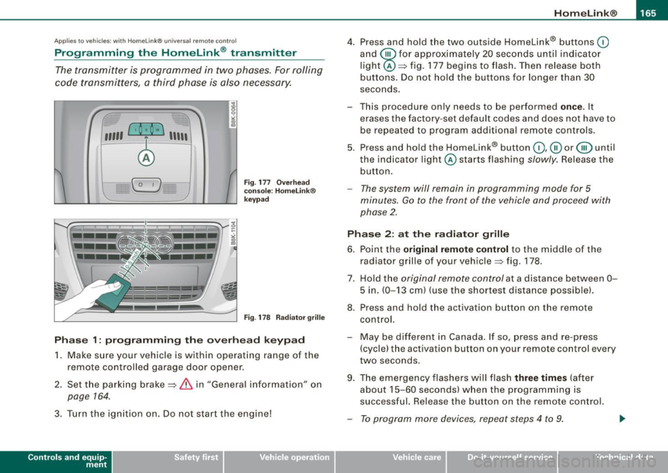
Fig . 177 Overhead
console: HomeLink ®
keypad
Fig . 178 Radiator grille
Phase 1: programming the overhead keypad
1. Make sure your vehicle is within operating range of the
remote controlled garage door opener.
2. Set the parking brake==>
& in "General information" on
page 764.
3. Turn the ignition on. Do not start the engine!
Contro ls and eq uip
ment
4. Press and hold the two outside Homelink® buttons 0
and @for approximately 20 seconds until indicator
light@==> fig. 177 begins to flash. Then release both
buttons. Do not hold the buttons for longer than
30
seconds.
- This procedure only needs to be performed
once . It
erases the factory-set default codes and does not have to
be repeated to program additional remote controls.
5. Press and hold the Homelink® button
0,@ or@ until
the indicator light @starts flashing slowly. Release the
button.
- The system will remain in programming mode for 5
minutes.
Go to the front of the vehicle and proceed with
phase 2.
Phase 2: at the radiator grille
6. Point the
original remote control to the middle of the
radiator grille of your vehicle==> fig. 178.
7. Hold the original remote control at a distance between
0-
5 in. (0-13 cm) (use the shortest distance possible).
8. Press and hold the activation button on the remote control.
- May be different in Canada . If so, press and re -press
(cycle) the activation button on your remote control every
two seconds.
9. The emergency flashers will flash
three times (after
about
15 -60 seconds) when the programming is
successful. Release the button on the remote control.
- To program more devices, repeat steps 4 to 9.
Vehicle care I I irechnical data
Page 182 of 360
___ S_a_ f_ e_ t-= y_ b_e_ l_ t _s _______________________________________________ _
- Make sure that your passengers also b uckle up and prop
erly wea r th eir sa fety belts.
Protect your childre n with a child restraint system appro
priate for t he size and age of the children.
The warning light i in the instrument cluster lights up when the
ignition is switched on as a reminder to fasten the safety belts. In
addition, you will hear a warning sound.
After the ignition is switched on, the warning tone will come on for about 6 seconds along w ith a ,!,-warning light in the ins trument
cluster if either the driver or (on USA models on ly) front seat
passenger has not fastened their safe ty belt. As soon as the driver
and front seat passenger have fastened the safety belt, the warning
tone wi ll stop and the warning light will go out.
If both the driver and front seat passenger have not buck led-up
within about 24 seconds after the warning tone has stopped, the
warning tone wi ll sound aga in for about 6 seconds . The warning
tone wi ll sound repeatedly for about 6 seconds at 24 second inter
va ls unti l both the driver and front passenger have buckled-up . The
safety belt warning system is active for about 5 minutes and during
t his time the wa rn ing light in the instrument c luster w ill stay on.
Fa sten your safety belt now and make sure th at your pa ssenger s
a lso proper ly put on the ir saf ety belt s. •
Why safety belts?
Frontal co11isions and the law of physics
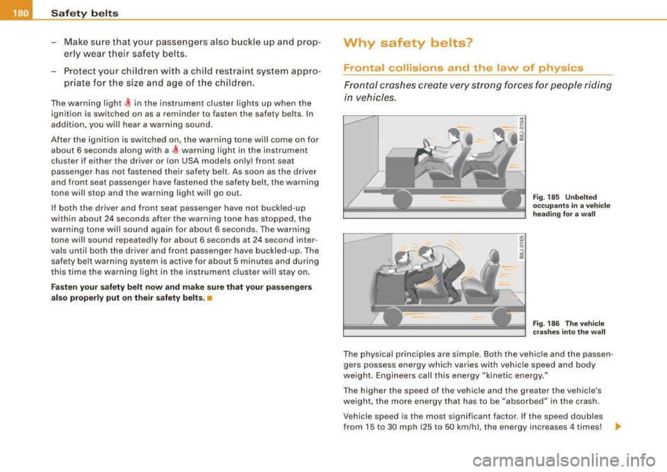
Front al crashes create very strong forces for pe ople rid ing
in vehicles.
Fi g. 185 U nbel ted
o cc up ants in a ve hicle
he ading for a wa ll
F ig . 18 6 The vehi cle
c ras hes in to the wa ll
The physical principles are simple. Both the vehicle and the passen
gers possess energy which varies with vehicle speed and body
we ight. Engineers cal l this energy "kinetic energy ."
T he higher the speed of the vehicle and the greater the vehic le's
we ight, the more energy that has to be "absorbed" in the crash .
Vehicle speed is the most significan t factor. If the speed doubles
from 15 to 30 mph (25 to 50 km/h), the energy increases 4 times! .,